EP1016965A1 - Système de gestion d'interruptions - Google Patents
Système de gestion d'interruptions Download PDFInfo
- Publication number
- EP1016965A1 EP1016965A1 EP99308976A EP99308976A EP1016965A1 EP 1016965 A1 EP1016965 A1 EP 1016965A1 EP 99308976 A EP99308976 A EP 99308976A EP 99308976 A EP99308976 A EP 99308976A EP 1016965 A1 EP1016965 A1 EP 1016965A1
- Authority
- EP
- European Patent Office
- Prior art keywords
- interrupt
- signal
- value
- counter
- serviced
- Prior art date
- Legal status (The legal status is an assumption and is not a legal conclusion. Google has not performed a legal analysis and makes no representation as to the accuracy of the status listed.)
- Withdrawn
Links
Images

Classifications
-
- G—PHYSICS
- G06—COMPUTING OR CALCULATING; COUNTING
- G06F—ELECTRIC DIGITAL DATA PROCESSING
- G06F9/00—Arrangements for program control, e.g. control units
- G06F9/06—Arrangements for program control, e.g. control units using stored programs, i.e. using an internal store of processing equipment to receive or retain programs
- G06F9/46—Multiprogramming arrangements
- G06F9/48—Program initiating; Program switching, e.g. by interrupt
- G06F9/4806—Task transfer initiation or dispatching
- G06F9/4812—Task transfer initiation or dispatching by interrupt, e.g. masked
- G06F9/4825—Interrupt from clock, e.g. time of day
Definitions
- This invention relates to an interrupt management system for managing interrupts in a processor control system.
- Many real time processor controlled systems contain programmable down-counters which count down from a predetermined value and on reaching zero generate an interrupt request signal. The down-counter then resets to the original predetermined value and begins decrementing again.
- the programmable down-counters allow the interrupts to be accurately generated at each predetermined period, the time taken for those interrupts to be completed i.e. serviced, by the real time system or processor controlling the real time system, can vary greatly. In extreme cases this time delay may exceed the predetermined period of the down-counter, causing one or more subsequent interrupts to be missed by the system.
- the object of embodiments of the present invention is to provide an interrupt management system which is capable of providing the above outlined advantages and overcoming the identified problems of known interrupt systems, in particular so that it is possible to ascertain when an interrupt has been missed and the delay in servicing an interrupt
- an interrupt management system comprising:
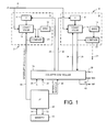
- FIG. 1 shows a schematic representation of an interrupt management system according to a preferred embodiment of the present invention.
- two down-counters a first down-counter A, 2, a second down-counter B, 4, a system processor 46, a memory 50 and a down-counter controller 24.
- the counters are described herein with reference to schematic blocks which could be implemented in software or hardware. It will be appreciated that as a matter of practicality the down-counter and counter controller could be implemented by registers in conjunction with software routines executed by the processor 46 and held in the memory 50.
- the value of a count register 16 in the first down-counter A is decremented upon receipt of each pulse of a clock signal 6.
- the clock signal 6 may be a system clock or any clock signal whose period is derived from the system clock.
- the current value in the count register 16 is output to a comparator 20. Also input into the comparator 20 is a zero signal provided from a target register 12. The comparator 20 compares the count value from count register 16 with the zero value held in target register 12 and when the count value equals zero, the comparator 20 produces an output signal 48.
- the output signal 48 has two functions. For the counter A it acts as a reset signal for the count register 16, resetting the count value to a predetermined value X, which is supplied from a reset register 8. The value X is loaded into the reset register 8 from the down-counter controller 24 via signal 30.
- the value X is predetermined by a user and is programmed via programming line 26 into the down-counter controller 24. Therefore, the down-counter A, 2, continuously counts down from value X to zero and resets to value X on receipt of the output signal 48.
- the output signal 48 is also input to the system processor 46 and acts as an interrupt request to trigger the system processor 46 to output a memory address 52 specifying the base location of an interrupt handling routine stored in memory block 50.
- the interrupt handling routine is output from the memory block via data line 54 to the system processor 46 whereupon the system processor proceeds to the interrupt functions determined by the interrupt handling routine.
- the system processor 46 outputs an interrupt serviced signal 44 to the down-counter controller 24.
- the second down-counter, B, 4 is described in terms of schematic blocks comprising a count register 18, a target register 14, a reset register 10 and a comparator 22.
- the count register 18 holds a count value which it decrements on receipt of the same clock signal 6 as is received by the count register 16.
- the initial value from which count register 18 counts down from is provided by value Y stored in the reset register 10.
- Value Y N*X, where N is an integer which is chosen such that the value Y is the highest value to which the count register 18 can be reset without causing it to overflow.
- Integer N is programmed via programming line 28 to the down-counter controller 24. Circuitry within the down-counter controller 24 multiplies N with X to produce value Y which is output via line 32 to reset register 10.
- the comparator 22 compares the count value of the count register 18 and the zero value stored in target register 14 and, if the count value equals zero outputs a signal (shown by the chained line 21 in Figure 1). As the operation of the interrupt management system is described in more detail hereinafter, it will be appreciated that the output signal from the comparator 22 is not normally produced.
- the down-counter controller 24 When the system processor 46 has completed an interrupt handling routine and has output an interrupt serviced signal 44, the down-counter controller 24 reads the current value from the count register 18 as indicated by line 36. A number of calculations are performed by the down-counter controller 24 using the current count value from the register 18 and the values of X and N in order to establish if any further interrupt request signals output via line 48 have not been acted upon by the system processor 46 while the system processor was servicing a previously received interrupt request signal. If an interrupt has been missed by the microprocessor, the down-counter controller 24 is able to calculate the number of such missed interrupts and the time delay (latency) which was required by the system processor 46 to service the last received interrupt request.
- the down-counter controller 24 outputs an interrupt missed flag (IMF), as indicated by line 42, to an I/O interface (not shown) to produce a system output to alert a system operator as to whether or not an interrupt has been missed, a signal N im on line 40 indicating the number of missed interrupts and a latency signal L on signal line 38 indicating the delay required by the system processor 46 to service the interrupt.
- IMF interrupt missed flag
- N im on line 40 indicating the number of missed interrupts
- L on signal line 38 indicating the delay required by the system processor 46 to service the interrupt.
- a counter register reset signal 34 is output to count register 18 in order to reset count register B.
- FIG. 2 is a timing diagram, showing a timing signal 100 representing counting by the count register 16 and a timing signal 102 representing counting by the count register 18.
- the value of the count register 18 has counted down to 15, as shown.
- the count register 16 has once again reached zero, at point (b), whereupon a second interrupt request is produced and the count register 16 resets once again to value X.
- the system processor 46 completes the first interrupt handling routine and generates a first interrupt serviced signal on signal line 44 which is input to the down-counter controller 24. This is illustrated in Figure 2 at point (f). At this point the value of the count register 18 has decremented down to 8. This value is read from the count register 18 by the down-counter controller 24. The number of clock cycles which the down-counter B has decremented by is illustrated in Figure 2 by the value d.
- N im (N-1)*X (N*X)-L with the number of missed interrupts being equal to the largest integer value of that expression.
- N im is output at signal line 40 by the down-counter controller 24.
- the down-counter controller 24 outputs a reset signal on signal line 34 to the counter register 18 to reset the count value.
- a reset signal on signal line 34 to the counter register 18 to reset the count value.
- the down-counter controller 24 uses the latency information to input a modified value of Y, denoted Y', to counter register 10.
- Value N is chosen such that value Y is the largest value which can be stored in the counter register 18 in order that under normal circumstances, the count register 18 never decrements to zero, thus ensuring that even if the latency of the system processor 46 is very long the latency and number of missed interrupts can still be calculated.
Landscapes
- Engineering & Computer Science (AREA)
- Software Systems (AREA)
- Theoretical Computer Science (AREA)
- Physics & Mathematics (AREA)
- General Engineering & Computer Science (AREA)
- General Physics & Mathematics (AREA)
- Bus Control (AREA)
Applications Claiming Priority (2)
| Application Number | Priority Date | Filing Date | Title |
|---|---|---|---|
| GB9827825 | 1998-12-17 | ||
| GBGB9827825.2A GB9827825D0 (en) | 1998-12-17 | 1998-12-17 | Interrupt management system |
Publications (1)
| Publication Number | Publication Date |
|---|---|
| EP1016965A1 true EP1016965A1 (fr) | 2000-07-05 |
Family
ID=10844433
Family Applications (1)
| Application Number | Title | Priority Date | Filing Date |
|---|---|---|---|
| EP99308976A Withdrawn EP1016965A1 (fr) | 1998-12-17 | 1999-11-11 | Système de gestion d'interruptions |
Country Status (3)
| Country | Link |
|---|---|
| US (1) | US6543000B1 (fr) |
| EP (1) | EP1016965A1 (fr) |
| GB (1) | GB9827825D0 (fr) |
Cited By (1)
| Publication number | Priority date | Publication date | Assignee | Title |
|---|---|---|---|---|
| EP1943565A4 (fr) * | 2005-09-23 | 2012-08-08 | Verisign Inc | Procede et systeme de chronometrage redondant |
Families Citing this family (11)
| Publication number | Priority date | Publication date | Assignee | Title |
|---|---|---|---|---|
| JP4147087B2 (ja) * | 2002-10-29 | 2008-09-10 | 株式会社ルネサステクノロジ | 情報処理通信装置 |
| KR100528476B1 (ko) * | 2003-07-22 | 2005-11-15 | 삼성전자주식회사 | 컴퓨터 시스템의 인터럽트 처리 장치 |
| US7272754B2 (en) * | 2003-09-27 | 2007-09-18 | International Business Machines Corporation | Implementation-efficient multiple-counter value hardware performance counter |
| JP2006121667A (ja) * | 2004-09-27 | 2006-05-11 | Matsushita Electric Ind Co Ltd | パケット受信制御装置及びパケット受信制御方法 |
| US7461283B2 (en) * | 2005-03-23 | 2008-12-02 | Texas Instruments Incorporated | Skip counter for system timer |
| US7805557B2 (en) * | 2005-07-12 | 2010-09-28 | Arm Limited | Interrupt controller and method for handling interrupts |
| US9262356B2 (en) * | 2006-12-15 | 2016-02-16 | Lantiq Beteiligungs-GmbH & Co.KG | Arbiter device and arbitration method |
| US7886177B2 (en) * | 2006-12-27 | 2011-02-08 | Intel Corporation | Method and apparatus of collecting timer ticks |
| JP5829890B2 (ja) * | 2011-11-02 | 2015-12-09 | ルネサスエレクトロニクス株式会社 | 半導体データ処理装置、タイムトリガ通信システム及び通信システム |
| US9715468B2 (en) * | 2014-11-04 | 2017-07-25 | Texas Instruments Incorporated | Method of providing timing information for interrupts |
| US9940272B1 (en) | 2015-04-09 | 2018-04-10 | Juniper Networks, Inc. | Hardware-based handling of missing interrupt propagation |
Citations (2)
| Publication number | Priority date | Publication date | Assignee | Title |
|---|---|---|---|---|
| US4538235A (en) * | 1982-08-19 | 1985-08-27 | Rockwell International Corporation | Microcomputer retriggerable interval counter |
| US5768620A (en) * | 1996-04-09 | 1998-06-16 | International Business Machines Corporation | Variable timeout method in a missing-interrupt-handler for I/O requests issued by the same operating system |
Family Cites Families (7)
| Publication number | Priority date | Publication date | Assignee | Title |
|---|---|---|---|---|
| US5535380A (en) * | 1994-12-16 | 1996-07-09 | International Business Machines Corporation | System to reduce latency for real time interrupts |
| US5797037A (en) * | 1995-03-31 | 1998-08-18 | Cirrus Logic, Inc. | Interrupt request control logic reducing the number of interrupts required for I/O data transfer |
| US5708814A (en) * | 1995-11-21 | 1998-01-13 | Microsoft Corporation | Method and apparatus for reducing the rate of interrupts by generating a single interrupt for a group of events |
| US5943500A (en) * | 1996-07-19 | 1999-08-24 | Compaq Computer Corporation | Long latency interrupt handling and input/output write posting |
| US5982814A (en) * | 1996-08-01 | 1999-11-09 | Pc-Tel, Inc. | Dynamic control of processor utilization by a host signal processing modem |
| KR100218675B1 (ko) * | 1996-12-04 | 1999-09-01 | 정선종 | 지능적 우선순위 결정 방식의 다중 인터럽트 제어기 및 그 제어 방법 |
| US6065089A (en) * | 1998-06-25 | 2000-05-16 | Lsi Logic Corporation | Method and apparatus for coalescing I/O interrupts that efficiently balances performance and latency |
-
1998
- 1998-12-17 GB GBGB9827825.2A patent/GB9827825D0/en not_active Ceased
-
1999
- 1999-11-11 EP EP99308976A patent/EP1016965A1/fr not_active Withdrawn
- 1999-11-22 US US09/444,678 patent/US6543000B1/en not_active Expired - Lifetime
Patent Citations (2)
| Publication number | Priority date | Publication date | Assignee | Title |
|---|---|---|---|---|
| US4538235A (en) * | 1982-08-19 | 1985-08-27 | Rockwell International Corporation | Microcomputer retriggerable interval counter |
| US5768620A (en) * | 1996-04-09 | 1998-06-16 | International Business Machines Corporation | Variable timeout method in a missing-interrupt-handler for I/O requests issued by the same operating system |
Non-Patent Citations (2)
| Title |
|---|
| ANONYMOUS: "Hardware Support for an Operating System Timer.", IBM TECHNICAL DISCLOSURE BULLETIN, vol. 34, no. 10B, March 1992 (1992-03-01), New York, US, pages 237 - 238, XP000302701 * |
| ANONYMOUS: "Watch Dog Timer Interface", IBM TECHNICAL DISCLOSURE BULLETIN, vol. 30, no. 11, April 1988 (1988-04-01), New York, US, pages 272 - 276, XP002093426 * |
Cited By (1)
| Publication number | Priority date | Publication date | Assignee | Title |
|---|---|---|---|---|
| EP1943565A4 (fr) * | 2005-09-23 | 2012-08-08 | Verisign Inc | Procede et systeme de chronometrage redondant |
Also Published As
| Publication number | Publication date |
|---|---|
| GB9827825D0 (en) | 1999-02-10 |
| US6543000B1 (en) | 2003-04-01 |
Similar Documents
| Publication | Publication Date | Title |
|---|---|---|
| EP1016965A1 (fr) | Système de gestion d'interruptions | |
| KR101391907B1 (ko) | 인터럽트 컨트롤러 | |
| EP1471431B1 (fr) | Ordinateur permettant de determiner dynamiquement un delai d'interruption | |
| KR19980043590A (ko) | 지능적 우선순위 결정 방식의 다중 인터럽트 제어기 및 그 제어 방법 | |
| US7181559B2 (en) | Message based transport mechanism for level sensitive interrupts | |
| EP1209810A1 (fr) | Modulateur de durée d'impulsion répondant aux signaux externes | |
| JP3317873B2 (ja) | データ転送制御装置 | |
| US5928348A (en) | Method of processing interrupt requests and information processing apparatus using the method | |
| JP3008895B2 (ja) | マルチプロセッサの負荷の均一化装置 | |
| US5371770A (en) | Pulse generating circuit for microcomputers | |
| EP0339782B1 (fr) | Système de traitement de données à bus partagé | |
| JP2577146B2 (ja) | プライオリティ制御回路 | |
| JP2908273B2 (ja) | ベクトル処理装置 | |
| JP3072168B2 (ja) | メモリ動作調停回路 | |
| US5920707A (en) | Bus controller and method therefor for supporting a live-line insertion/disconnection in a synchronous bus | |
| US5497481A (en) | Microcomputer computer system having plural programmable timers and preventing memory access operations from interfering with timer start requests | |
| US5483648A (en) | Circuit for determining the arrival times of control signals supplied to microprocessors | |
| JPH0675780A (ja) | 割込み制御装置 | |
| KR19980044600A (ko) | 순차식 pci 버스용 다중 인터럽트 제어장치 및 방법 | |
| JPH0434629A (ja) | メモリアクセス制御装置のビジーチェック方式 | |
| JP3308670B2 (ja) | イベントドリブン型処理装置の故障検出装置 | |
| JPH033048A (ja) | 情報処理装置 | |
| JP2896478B2 (ja) | リモートコントロールパルス受信回路 | |
| JPH0894660A (ja) | パルス計測装置 | |
| KR19980044002A (ko) | 절충식 pci 버스용 다중 인터럽트 제어 장치 및 방법 |
Legal Events
| Date | Code | Title | Description |
|---|---|---|---|
| PUAI | Public reference made under article 153(3) epc to a published international application that has entered the european phase |
Free format text: ORIGINAL CODE: 0009012 |
|
| AK | Designated contracting states |
Kind code of ref document: A1 Designated state(s): DE FR GB IT |
|
| AX | Request for extension of the european patent |
Free format text: AL;LT;LV;MK;RO;SI |
|
| 17P | Request for examination filed |
Effective date: 20010102 |
|
| AKX | Designation fees paid |
Free format text: DE FR GB IT |
|
| 17Q | First examination report despatched |
Effective date: 20071213 |
|
| STAA | Information on the status of an ep patent application or granted ep patent |
Free format text: STATUS: THE APPLICATION IS DEEMED TO BE WITHDRAWN |
|
| 18D | Application deemed to be withdrawn |
Effective date: 20091118 |