EP1017008B1 - Dispositif et méthode de comparaison d'images - Google Patents
Dispositif et méthode de comparaison d'images Download PDFInfo
- Publication number
- EP1017008B1 EP1017008B1 EP99125650A EP99125650A EP1017008B1 EP 1017008 B1 EP1017008 B1 EP 1017008B1 EP 99125650 A EP99125650 A EP 99125650A EP 99125650 A EP99125650 A EP 99125650A EP 1017008 B1 EP1017008 B1 EP 1017008B1
- Authority
- EP
- European Patent Office
- Prior art keywords
- image
- region
- sub
- rectangular
- maximum correlation
- Prior art date
- Legal status (The legal status is an assumption and is not a legal conclusion. Google has not performed a legal analysis and makes no representation as to the accuracy of the status listed.)
- Expired - Lifetime
Links
Images


Classifications
-
- G—PHYSICS
- G06—COMPUTING OR CALCULATING; COUNTING
- G06V—IMAGE OR VIDEO RECOGNITION OR UNDERSTANDING
- G06V40/00—Recognition of biometric, human-related or animal-related patterns in image or video data
- G06V40/10—Human or animal bodies, e.g. vehicle occupants or pedestrians; Body parts, e.g. hands
- G06V40/12—Fingerprints or palmprints
- G06V40/1365—Matching; Classification
Definitions
- the present invention relates to a technique of collating image data, and more particularly to a technique of collating images, which is suitable for certifying the person himself and which collation is performed using finger print image data.
- US 4,581,760 discloses a fingerprint verification method based on using two relatively small rectangular reference segments which are extracted from an enrolled fingerprint image.
- the segment images are provided in digitized form as a series of "ones” and “zeros", corresponding to ridges and valley zones.
- the reference segments are compared with subfields of an fingerprint image scanned in, whereby the format is the same format as the format of the reference segments.
- the subfields are moved dot by dot at a time within a predetermined range of the fingerprint image and correlation coefficients concerning separately "ones” and “zeros” are calculated.
- Via a special algorithm including several screening stages it is determined based on the maximum correlation coefficients detected whether the fingerprint image which was scanned in has to be rated matching with the fingerprint image already enrolled.
- Ratkovic et al. published a paper in "The Rand Corporation XP 199727A” on “Concepts for a Next Generation Automatic Fingerprint System”, in which they suggest to automate fingerprint matching detection by including sub-area correlation in order to overcome computer loading limitations for handling problems due to image rotation, stretching and noise.
- FIG. 1 is a block diagram illustrating the principle of the present invention.
- a first image data 1a is image data that is registered in a database beforehand. In a finger collation system, a registered fingerprint corresponds to this first image data.
- a second image data 1b is image data that has been obtained using an image reader, etc..
- a fingerprint to be collated corresponds to this second image data.
- a defining section 3 defines a plurality of regions over the first image data 1a. This defining of each region is performed by locating a template having a predetermined shape at a predetermined position on the image data. Each template may be of the same shape and size, or be of a different shape and size. Further, each template may be positioned in a state of its being partly overlapped upon another on the image.
- An extracting section 4 serves to set an image region, with respect to the second image data, that has the same size and shape as those of a corresponding one of the respective templates that have been positioned on the first image by the defining section 3. It serves to move the image region that has been thus set. It thereby serves to find out on the second image a region having a maximum correlation with the first image data on which the corresponding template is positioned. The region that has been thus found out is called "a maximum correlation region".
- a determining section 5 examines the positional relationship of the templates defined by the defining section 3 and the positional relationship of the maximum correlation regions found out by the extracting section 4. According to the extent by which the both positional relationships differ from each other, the determining section 5 determines the degree of identicalness, or the degree of similarity, between the first image and the second image data.
- the image data that even binarized data enables determination and that, however, multi-gradation image data is more preferable in order to make a perfect determination of the correlation. Further, it is also possible to set the first image as the fingerprint to be collated and set the second image as the registered fingerprint by interchanging the first image and the second image data with each other.
- the above-described functions of the defining section 3, extracting section 4, and determining section 5 can be performed by a computer.
- An explanation will now be given of an embodiment in the form of a fingerprint collation apparatus that uses a computer.
- the fingerprint collation processing as later described is prepared as a program that is to be executed by the computer. Then this program is stored in a storage device of the computer and is executed by the central operation-processing unit.
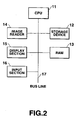
- FIG. 2 is a block diagram illustrating the construction of the apparatus for collating a fingerprint according to the first embodiment of the present invention.
- This apparatus is constructed of a CPU 11, a storage device 12, a RAM 13, an image reader 14, a display section 15, and an input section 16, which are connected to one another via a bus line 17.
- the CPU 11 is a central operation-processing unit, which, in accordance with a control program stored in the storage device 12, controls the entire operation of the fingerprint collation apparatus (hereinafter referred to merely as "the present apparatus") while using the RAM 13 as a work area.
- the CPU 11 performs the fingerprint collation processing as later described by executing the control program.
- the storage device 12 is composed of a ROM, a hard disk, etc..
- the storage device 12 previously stores therein the above-described control program that is read out from the CPU 11 immediately after turning on a power source of the present apparatus.
- the storage device 12 also previously stores therein subject's registered fingerprint that corresponds to the first image data 1a illustrated in FIG. 1.
- the RAM 13 is a work memory that the CPU 11 uses when executing the above-described control program.
- the image reader 14 is a device for obtaining a subject' fingerprint to be collated that corresponds to the second image data 1b illustrated in FIG. 1.
- the image reader 14 is, for example, an image scanner, or an image sensor such as a CCD (charge coupled device).
- the display section 15 is a display device such as a CRT or a liquid crystal display, which makes a display of the determination result of the collation, which determination result corresponds to a determination result 2 illustrated in FIG. 1.
- the input section 16 is an input device such as a keyboard device, by means of which a user of the present apparatus instructs the CPU 11 to obtain a fingerprint to be collated, or to start the fingerprint collation processing as later described.
- the fingerprint collation program was stored in the storage device 12 beforehand as mentioned above. It can be also arranged that, from a storage medium having a fingerprint collation processing program stored therein, this fingerprint collation processing program be made to be read by a reading device equipped to a computer that corresponds to the storage medium. For example, this fingerprint collation-processing program is temporarily stored in a main memory, and the program is executed by the central processing unit.
- FIG. 3 illustration is made of an example of a computer-readable storage medium that stores therein the fingerprint collation-processing program.
- the storage media there can be used a storage device 22 such as a ROM or a hard disk device, which is equipped to a computer 21 as an accessory in a built-in form or in a form externally equipped thereto, portable storage media 23 such as a floppy disk, MO (magneto-optical disk), CD-ROM, or DVD-ROM, a storage device 26 that is an accessory to a program server that is a computer connected to the computer 21 via a network 24, etc.
- a storage device 22 such as a ROM or a hard disk device, which is equipped to a computer 21 as an accessory in a built-in form or in a form externally equipped thereto
- portable storage media 23 such as a floppy disk, MO (magneto-optical disk), CD-ROM, or DVD-ROM
- a storage device 26 that is an accessory to a program server that is a computer connected to the
- FIG. 4 is a flow chart that, of the control process of the present apparatus as a whole realized by the execution of the above-described control program by the CPU 11, illustrates the contents to be processed of a fingerprint collation processing having particular relevance to the present invention.
- the contents of the pieces of processing performed in step S11 and step S14 correspond to the pieces of processing that are performed in the defining section 3 of FIG. 1.
- the contents of the pieces of processing performed in steps S12, S13 and step S16 correspond to the pieces of processing that are performed in the extracting section 4.
- the contents of the pieces of processing performed in steps S18 and step S19 correspond to the pieces of processing that are performed in the determining section 5.
- FIGS. 5A and 5B illustrate examples of the images of fingerprints used to explain the fingerprint collation processing.
- FIG. 5A illustrates a subject's registered fingerprint that is stored in the storage device 12 beforehand.
- FIG. 5B illustrates a subject's fingerprint to be collated, which has been sampled by the image reader 14. Also, it is assumed that each of the both images of these figures be a multi-gradation image.
- FIGS. 6A and 6B show a memory map regarding the fingerprint collation processing, illustrating the state of use of the RAM 13, that prevail when the CPU 11 performs the fingerprint collation processing.
- the fingerprint collation processing that is performed by the CPU 11 will hereinafter be explained along FIG. 4 while referring to FIGS. 5A, 5B, 6A and 6B.
- a main template "mt” is positioned on a registered fingerprint image "A" as illustrated in FIG. 5A, in order to define a rectangular region over the image of the registered fingerprint (step S11).
- the size of this main template "mt” may be arbitrary so long as the required collation precision of a collation between fingerprints is obtained.
- a maximum correlation region MT that corresponds to the region indicated by the main template "mt” is searched from the fingerprint image "B" of the fingerprint to be collated.
- This searching operation is performed as follows. Setting is performed of a rectangular region having the same shape and size as those of the main template "mt" with respect to the image "B" of the collation fingerprint. Then, this rectangular region is two-dimensionally scanned in units of a pixel. Then, the correlation coefficient between the rectangular region and the region, which is indicated by the main template "mt", is calculated each time the movement is made.
- the rectangular region that is positioned where the correlation coefficient is maximum is set as being a maximum correlation region MT (step S12). The calculation of the correlation coefficient will be described later.
- These coordinates are set to be mt(x 0 , y 0 ) and MT(X 0 , Y 0 ), respectively. They are stored respectively in predetermined areas of the RAM 13 illustrated in FIGS. 6A and 6B (step S13).
- step S14 On the image "A" of the registered fingerprint are positioned sub-templates st1 to st4 so that the respective apexes of the square main template "mt" may be positioned at their centers, respectively, to thereby define corresponding rectangular regions (step S14).
- the position of the sub-templates can be arbitrarily made.
- the number of the sub-templates is not limited to four, and this number may be arbitrary so long as the collation precision of a collation between the fingerprints is obtained as required.
- the size of the rectangular region that is defined here as mentioned above may be similarly arbitrary.
- ⁇ i x i - x 0 - ( x i - x 0 ) , ( y i - y 0 ) - ( y i - y 0 )
- the predetermined value which is used here, is the one that is obtained, as a value enable to obtain a desired collation precision, by actually calculating the ⁇ i values from the items of fingerprint image data that have been sampled from a plurality of persons, and in accordance with the distribution of these calculation results.
- the foregoing processing is the fingerprint collation processing.
- the shape of the main template "mt" and sub-template st i has been made rectangular
- the shape of these templates is not limited to a rectangular one. Namely, each of these templates may be of any given shape.
- the size and shape of the "mt" and those of the MT as well as the size and shape of the st i and those of the ST i be the same to each other. However, even if there is a small difference between the two, such difference can be permitted so long as a required level of collation precision of one fingerprint with another is obtained.
- the collation determination in addition to the method of evaluating the ⁇ i in the above-described processing, it is also possible to adopt various methods such as a determination that is performed based on the difference in shape or area between a figure, that is formed using, for example, the st i as an apex, and a figure, that is formed using the ST i as an apex.
- RA(i, j) and RB(m, n) respectively represent the pixels that are contained respectively in the rectangular region RA and the rectangular region RB, provided. It is also assumed that the sum totals of the pixels contained respectively in the rectangular region RA and the rectangular region RB be equal. Also, it is assumed that X ij and Y mn respectively represent signal intensities, each of which is the multi-gradation value indicating the thick and thin of a corresponding pixel.
- N represents the sum total of the pixels contained in the corresponding rectangular region.
- ⁇ represents the sum total of the signal intensities about all the pixels contained in the corresponding rectangular region. Namely, the above equation shows the average value of the signal intensities about the pixels contained in the corresponding region.
- ⁇ Z 2 > N - 1 ⁇ ⁇ Z pq 2
- the above equation shows the value of root mean square of the signal intensities about the pixels contained in the corresponding rectangular region.
- the correlation coefficient C AB between the rectangular region RA and the rectangular region RB can be calculated using the following equation that is expressed using the above-defined equations.
- C AB ⁇ XY > - ⁇ X > ⁇ Y > / ( ⁇ X 2 > - ⁇ X ⁇ > 2 ) ( ⁇ Y 2 > - ⁇ Y ⁇ > 2 ⁇ ) 1 / 2
- ⁇ XY > 1 / N ⁇ ⁇ ⁇ X ij ⁇ Y mn
- the following calculation may be performed. Namely, calculation that is performed using only the pixels arrayed on the line constituting any one row within the rectangular region, calculation that is performed using only the pixels contained in part of the rectangular region, or calculation that is performed using the pixels that have been selected by arbitrarily thinning from within the rectangular region may be performed. Even when these calculations are performed, there are no problems if a required level of collation precision of one fingerprint with another is obtained. Using these procedures of calculation, the number of pixels used as an object with respect to which the correlation coefficient is calculated is reduced. As a result of this, the amount of calculation is reduced. Therefore, such procedures of calculation are useful. Also, other methods of calculation of the correlation coefficients may be adopted for the above-described fingerprint collation processing.
- a subject In the fingerprint collation, a subject is made to put his finger on a fingerprint reader of the fingerprint collation apparatus and to have his fingerprint to be collated read out by this fingerprint reader. At this time, when the position at which the subject has put his finger gets out of the proper position, this inconveniently causes an erroneous determination result to be produced.
- main template and the sub-template be both rectangular in shape and the same in size, and that the sub-templates each be positioned so as to contact with their corresponding apex of the main template.
- step S101 the main template "mt” representing a rectangular region is positioned on the registered fingerprint image "A", as illustrated in FIG. 8A.
- the size and the shape of this main template “mt” may be arbitrary so long as a required level of collation precision of one fingerprint with another is obtained. It is assumed now that (x 0 , y 0 ) represents the coordinates for particularizing the position on the registered image "A" of the main template “mt” that has been defined here as mentioned above, here the coordinates of the center of gravity of the main template "mt” that is rectangular.
- step S102 on the registered image "A" are positioned the sub-templates st i (i ⁇ 1) that define a plurality of rectangular regions that are different from that which is defined by the main template "mt".
- i 4.
- the sub-templates st 1 to st 4 that are four rectangles are defined in the positional relationship illustrated in FIG. 8A in such a way as to surround the main template "mt".
- the size and the shape of these sub-template st i also may be arbitrary so long as a required level of collation precision of one fingerprint with another is obtained.
- (x i , y i ) represents the coordinates for particularizing the position on the registered image "A" of the sub-template st i that has been defined here as mentioned above, here the coordinates of the center of gravity of the sub-template st i that is rectangular.
- step S103 a rectangular region that has the same shape and size as those of the main template "mt" is set on the fingerprint image "B" to be collated. While this rectangular region is being scanned over this image "B”, calculation is performed of the correlation coefficient between this rectangular region and the region on the image "A" designated by the main template "mt", one after another.
- step S104 as a result of the successive calculation of the correlation coefficient, determination is made of the above-described rectangular region, regarding which the correlation coefficient between itself and the main template "mt" is maximum.
- This rectangular region is set as a region MT.
- the coordinates for particularizing the position on the image "B" of this region MT which are the coordinates of the region MT corresponding to the coordinates (x 0 , y 0 ) of the main template "mt", are represented as (X 0 , Y 0 ).
- step S105 it is determined whether the region MT belongs to an effective region E that is set on the image "B". Concretely, it is determined whether the coordinates (X 0 , Y 0 ) for particularizing the position of the region MT are included within an range E x,y that represents the effective region E. If this determination result is Yes, the flow proceeds to step S107 while if it is No the flow proceeds to step S106.
- the "effective region E” represents the range on the image "B", wherein the region MT can exist, and within which it is possible to obtain a maximum correlation region corresponding to the sub-template st i , necessary for collation.
- the range E x,y that is expressed by the following equation is set on the image "B".
- FIG. 8B illustrates a state where, in a case where having defined the main template "mt" and the sub-template st i on the registered image "A" as illustrated in FIG. 8A, the range E x,y of the effective region E is set on the image "B".
- the W i and the H i represent the width (the length as viewed in the x direction) and the height (the length as viewed in the y direction) of the sub-template st i .
- the WIDTH and the HEIGHT respectively represent the width (the length as viewed in the x direction) and the height (the length as viewed in the y direction) of each of the image "A" and the image "B” having the same size.
- the x i SEARCH and the y i SEARCH represent the ranges for searching on the image "B" the maximum correlation region corresponding to the sub-template st i positioned on the image "A". For each of them, for example, a value that corresponds to four to six pixels or so as taken in units of a pixel of the image data is used. Also, the MAX[p, q] represents the function for obtaining a larger one of the p and the q value (that in a case where the both are equal is either one of them).
- FIG. 12 is a view illustrating the procedure of setting the effective region E.
- FIG. 12 is given for the purpose of explaining the ⁇ x and the ⁇ x of the above equation (4), and illustrates only the upper side portion of the image "A". It is to be noted that for brevity of explanation it is assumed that the sub-templates st 3 and st 4 be left out of consideration.
- step S105 If in this step S105 it has been determined that the region MT falls out of the effective region E, namely if as in the relationship between FIG. 9A and FIG. 9B the region MT on the image "B" corresponding to the main template "mt" on the registered image "A” falls outside the range E x,y of the effective region E, the following procedure is taken. Namely, in step S106, the sub-template st i is positioned on the registered image "A" again after correcting the position thereof. The re-positioning of the sub-template st i is performed in accordance with the procedure illustrated in FIG. 13.
- FIG. 13 is a flow chart illustrating the contents to be processed of a re-positioning processing for re-positioning the sub-template.
- This re-positioning processing is the processing for re-locating the sub-template st i whose position is particularized by the coordinates (x i , y i ) to a position that is particularized by the coordinates (xr i , yr i ).
- step S201 and step S203 it is determined whether the region MT falls within the range of the effective region E (step S201 and step S203).
- step S206 and step S208 it is similarly determined whether the region MT falls within the range of the effective region E.
- yr i y i , namely the position of the sub-template st i is maintained to be as is at the original value (step S210).
- FIG. 10A illustrates the result of re-positioning that has been performed in a case where the region MT on the image "B" fell out of the range E x,y of the effective region E to the right as illustrated in FIG. 9B.
- FIG. 10A illustrates the result wherein, in the case, the sub-templates st 1 to st 4 previously defined as illustrated in FIG. 8A have been moved leftwards and thus re-positioned.
- FIG. 10B illustrates the region MT corresponding to the main template "mt" in FIG. 10A. Since in this case the position of the main template "mt" is not moved, the position of the region MT is not moved from the position illustrated in FIG. 9B.
- step S107 a rectangular region that is the same in shape and in size as the sub-template st i is set on the image "B". While scanning this rectangular region over this image "B", the correlation coefficient between this region and the sub-template st i is calculated one after another.
- the method of calculation of the correlation coefficient uses here the one that was used in the previously stated step S103, other methods of calculation thereof may be adopted.
- step S108 as a result of the successive calculations of the correlation coefficients, the rectangular region, regarding which the correlation coefficient between itself and the sub-template st i has become maximum, is determined.
- This rectangular region is set to be a region ST i .
- step S109 it is determined whether the region ST i has finished being detected with regard to all the sub-templates st i . If the determination result is Yes, the flow proceeds to step S110. On the other hand, if the determination result is No, the flow returns to step S107, in that the above-described processing for determining the region ST i is repeatedly performed.
- FIGS. 11A and 11B illustrate, regarding all of the re-positioned sub-templates st 1 to st 4 , the results of the corresponding regions ST 1 to ST 4 that have been obtained, together with the main template "mt" and its corresponding region MT.
- step S110 the distribution of the positions of the main template "mt” and the sub-template st i in the image data "A” is compared with the distribution of the positions of the region MT and the region ST i in the image data "B". By this comparison is evaluated the identicalness between the image "A" (the registered fingerprint) and the image "B" (the fingerprint to be collated).
- the evaluation on the identicalness that is executed in this step is substantially the same as the processing that is performed in step S19 of FIG. 4 and that was explained as the first embodiment. It is to be noted that, when evaluating the identicalness, it is possible to exclude the main template "mt" and the region MT from the objects to be evaluated. It is also possible, with this exclusion, to perform evaluation through only the comparison of the distribution of the positions of the sub-template st i and the distribution of the positions of the region ST i .
- the fingerprint collation processing that has up to here been explained is executed through the operation of the CPU 11, and the collation of the fingerprints is thereby performed in the present apparatus.
- each of the main template "mt", sub-template st i , region MT, and region . ST i has been made to be of a rectangular shape
- the shape of these templates and regions is not limited to being rectangular.
- the shape may be any desired one.
- the relationship of position of the main template "mt" relative to the sub-template st i or vice versa, the both templates being defined beforehand, has been determined, in each of the above-described embodiments of the present invention, as follows. Namely, the both templates have been positioned in such a positional relationship wherein the main template "mt" and the sub-template st i contact with each other as illustrated in FIG. 8A. However, the both templates may also be positioned and thereby defined in such a positional relationship wherein the two partially overlap one upon the other, or in such a positional relationship wherein the two are completely separated from each other.
- each of the sub-templates st i has been re-positioned by being moved by the same distance.
- it may be also arranged to make different the movement distance of one sub-template st i from the original position thereof to the re-positioning thereof from the movement distance of another in correspondence with that direction.
- the xr i is determined from the relationship of the x coordinate X 0 for particularizing the position of the region MT with the above-described ⁇ x and the ⁇ x that represent the range in the x direction of the effective region E, as follows.
- the yr i is determined from the relationship of the x coordinate Yo for particularizing the position of the region MT with the above-described ⁇ y and the ⁇ y that represent the range in the y direction of the effective region E, as follows.
- the following merit will be obtained. Namely, if so, even when the region MT is outside the effective region E, it becomes possible, according to the positional relationship of the both regions, to perform the fingerprint collation without re-locating part of the sub-templates. Namely, it becomes possible to do so with those sub-templates being kept as were when they were initially defined. In such a case, the period of time that is required for the re-positioning processing of the sub-template is shortened, with the result that it is possible to shorten the processing time period needed for the fingerprint collation processing.
Landscapes
- Engineering & Computer Science (AREA)
- Human Computer Interaction (AREA)
- Physics & Mathematics (AREA)
- General Physics & Mathematics (AREA)
- Multimedia (AREA)
- Theoretical Computer Science (AREA)
- Collating Specific Patterns (AREA)
- Image Analysis (AREA)
- Apparatus For Radiation Diagnosis (AREA)
- Facsimile Image Signal Circuits (AREA)
Claims (15)
- Appareil de rapprochement d'images pour déterminer l'identité entre une première image et une deuxième image, l'une avec l'autre, caractérisé comme comportant :une section (3) définissant une région de référence, configurée pour définir une région de référence rectangulaire dans ladite première image, comme modèle ;une section de recherche de corrélation maximum (4), configurée pour rechercher une corrélation maximum avec la région de référence ;caractérisé comme comportant en outre :une section (3) définissant des sous-régions, configurée pour définir des sous-régions rectangulaires situées aux quatre coins de la région de référence rectangulaire, comme sous-modèles ;une section (4) de recherche de sous-régions de corrélation maximum, configurée pour rechercher des sous-régions de corrélation maximum dans la deuxième image, qui ont des corrélations maximums avec les sous-régions rectangulaires dans la première image ; etune section (5) de détermination, configurée pour déterminer l'identité entre ladite première image et ladite deuxième image, sur la base d'une différence entre une relation de position entre chacune des sous-régions rectangulaires dans la première image et une relation de position entre les sous-régions de corrélation maximum dans la deuxième image.
- Appareil de rapprochement d'images selon la revendication 1, caractérisé comme comportant en outre :un détecteur (S105), configuré pour détecter si la première région de corrélation maximum recherchée par la section (4) de recherche de corrélation maximum est dans une relation prédéterminée à ladite deuxième image ; etune section de redéfinition (S106), configurée pour définir les sous-régions rectangulaires qui ont été définies par la section définissant les sous-régions quand ledit détecteur détecte que la région de corrélation maximum est dans la relation prédéterminée à ladite deuxième image.
- Appareil de rapprochement d'images selon la revendication 2, caractérisé en ce que :ledit détecteur détecte que la région de corrélation maximum est déplacée de ladite deuxième image d'une quantité qui est plus grande qu'une quantité prédéterminée ; etladite section de redéfinition est adaptée pour déplacer les sous-régions rectangulaires conformément à une quantité de déplacement détectée.
- Appareil de rapprochement d'images selon la revendication 1, caractérisé en ce que :ladite première image est une image d'empreinte digitale de référence qui est enregistrée, et ladite deuxième image est une image d'empreinte digitale qui doit être rapprochée de ladite image d'empreinte digitale de référence.
- Appareil de rapprochement d'images selon l'une des revendications 1 à 4, caractérisé en ce que ladite section de recherche (4) de la région de corrélation maximum comporte :une section configurée pour créer, dans la deuxième image, une région correspondante de la région de référence rectangulaire ; et une section configurée pour calculer une corrélation entre la région de référence rectangulaire et la région correspondante tout en déplaçant la région correspondante.
- Support d'enregistrement lisible par ordinateur ayant en mémoire un programme de rapprochement d'images pour déterminer l'identité entre une première image et une deuxième image, l'une avec l'autre, le programme comportant :un moyen de codage de programme lisible par ordinateur pour permettre à un ordinateur de rechercher une région de corrélation maximum dans ladite deuxième image, qui a une corrélation maximum avec une région de référence rectangulaire définie dans la première image comme un modèle ;un moyen de codage de programme lisible par ordinateur pour permettre à un ordinateur de définir des sous-régions rectangulaires situées aux quatre coins de la région de référence rectangulaire comme sous-modèle ;caractérisé en ce qu'il comporte en outre:un moyen de codage de programme lisible par ordinateur pour permettre à un ordinateur de rechercher des sous-régions de corrélation maximum dans la deuxième image, qui ont des corrélations maximums avec les sous-régions rectangulaires dans la première image ; etun moyen de codage de programme lisible par ordinateur pour permettre à un ordinateur de déterminer l'identité entre ladite première image et ladite deuxième image, sur la base d'une différence entre une relation de position entre les sous-régions rectangulaires dans la première image et une relation de position entre les sous-régions de corrélation maximum dans la deuxième image.
- Support d'enregistrement selon la revendication 6, caractérisé en ce que le programme comporte en outre :un moyen de codage de programme lisible par ordinateur pour permettre à un ordinateur de détecter si la région de corrélation maximum recherchée est dans une relation prédéterminée à ladite deuxième image ; etun moyen de codage de programme lisible par ordinateur pour permettre à un ordinateur de redéfinir les sous-régions rectangulaires quand on détecte que la région de corrélation maximum est dans la relation prédéterminée à ladite deuxième image.
- Support d'enregistrement selon la revendication 7, caractérisé en ce que :ledit moyen de codage de programme lisible par ordinateur pour permettre à un ordinateur de détecter et de comprendre un moyen de codage de programme lisible par ordinateur pour permettre à un ordinateur de détecter si la région de corrélation maximum est déplacée de ladite deuxième image d'une quantité qui est plus grande qu'une quantité prédéterminée, etledit moyen de codage de programme lisible par ordinateur pour permettre à un ordinateur de redéfinir et de comprendre un moyen de codage de programme lisible par ordinateur pour permettre à un ordinateur de déplacer les sous-régions rectangulaires conformément à une quantité de déplacement détectée.
- Support d'enregistrement selon la revendication 6, caractérisé en ce que dans ladite première image il y a une image d'empreinte digitale de référence qui est enregistrée, et ladite deuxième image est une image d'empreinte digitale qui doit être rapprochée de l'image d'empreinte digitale de référence.
- Support d'enregistrement selon l'une quelconque des revendications 6 à 9, caractérisé en ce que ledit moyen de codage de programme lisible par ordinateur pour permettre à un ordinateur de rechercher la région de corrélation maximum comporte :un moyen de codage de programme lisible par ordinateur pour permettre à un ordinateur de fixer, dans la deuxième image, une région correspondante de la région de référence rectangulaire ; etun moyen de codage de programme lisible par ordinateur pour permettre à un ordinateur de calculer une corrélation entre la région de référence rectangulaire et les régions correspondantes en déplaçant la région correspondante.
- Procédé de rapprochement d'images pour déterminer l'identité entre une première image et une deuxième image, l'une avec l'autre,
caractérisé en ce qu'il comporte :un pas de définition pour définir une région de référence rectangulaire comme modèle ;un pas de recherche pour rechercher une corrélation maximum avec la région de référence rectangulaire ;caractérisé en ce qu'il comporte en outre :un pas de définition pour définir des sous-régions rectangulaires situées aux quatre coins de la région de référence rectangulaire comme sous-modèle ;un pas de recherche pour rechercher des sous-régions de corrélation maximum dans la deuxième image qui ont des corrélations maximums avec les sous-régions rectangulaires dans la première image ; etun pas de détermination pour déterminer l'identité entre ladite première image et ladite deuxième image sur la base d'une différence entre une relation de position entre les sous-régions rectangulaires dans la première image et une relation de position entre les sous-régions de corrélation maximum dans la deuxième image. - Procédé de rapprochement d'images selon la revendication 11, caractérisé en ce qu'il comporte en outre :un pas de détection configuré pour détecter si la recherche de la région de corrélation maximum est dans une relation prédéterminée à ladite deuxième image ; etun pas de redéfinition configuré pour redéfinir des sous-régions rectangulaires quand ledit pas de détection détecte que la région de corrélation maximum est dans la relation prédéterminée à ladite deuxième image.
- Procédé de rapprochement d'images selon la revendication 12, caractérisé en ce que :ledit pas de détection comprend de détecter si la région de corrélation maximum est déplacée de ladite deuxième image, d'une quantité qui est plus grande qu'une quantité prédéterminée ; etledit pas de redéfinition comprend de déplacer les sous-régions rectangulaires conformément à une quantité de déplacement détectée.
- Procédé de rapprochement d'images selon la revendication 11, caractérisé en ce que ladite première image est une image d'empreinte digitale de référence qui est enregistrée, et ladite deuxième image est une image d'empreinte digitale à rapprocher de l'image d'empreinte digitale de référence.
- Procédé de rapprochement d'images selon l'une des revendications 11 à 13, caractérisé en ce que le pas de recherche de ladite région de corrélation maximum comporte :de créer dans ladite deuxième image une région correspondant à la région de référence rectangulaire ; etde calculer une corrélation entre la région de référence rectangulaire et la région correspondante, tout en déplaçant la région correspondante.
Applications Claiming Priority (4)
| Application Number | Priority Date | Filing Date | Title |
|---|---|---|---|
| JP37220598A JP3386733B2 (ja) | 1998-12-28 | 1998-12-28 | 画像データ照合方法及び画像データ照合装置並びに画像データ照合プログラムを記憶した記憶媒体 |
| JP37220598 | 1998-12-28 | ||
| JP16676899A JP3567259B2 (ja) | 1999-06-14 | 1999-06-14 | 画像データ照合方法及び画像データ照合装置並びに画像データ照合プログラムを記憶した記憶媒体 |
| JP16676899 | 1999-06-14 |
Publications (3)
| Publication Number | Publication Date |
|---|---|
| EP1017008A2 EP1017008A2 (fr) | 2000-07-05 |
| EP1017008A3 EP1017008A3 (fr) | 2002-07-31 |
| EP1017008B1 true EP1017008B1 (fr) | 2007-04-04 |
Family
ID=26491034
Family Applications (1)
| Application Number | Title | Priority Date | Filing Date |
|---|---|---|---|
| EP99125650A Expired - Lifetime EP1017008B1 (fr) | 1998-12-28 | 1999-12-22 | Dispositif et méthode de comparaison d'images |
Country Status (5)
| Country | Link |
|---|---|
| US (1) | US6707934B1 (fr) |
| EP (1) | EP1017008B1 (fr) |
| AT (1) | ATE358854T1 (fr) |
| DE (1) | DE69935705T2 (fr) |
| TW (1) | TW522344B (fr) |
Families Citing this family (14)
| Publication number | Priority date | Publication date | Assignee | Title |
|---|---|---|---|---|
| US6685000B2 (en) * | 2000-05-19 | 2004-02-03 | Kabushiki Kaisha Nippon Conlux | Coin discrimination method and device |
| FR2816427B1 (fr) * | 2000-11-03 | 2003-10-24 | France Telecom | Dispositif et procede de controle d'acces par traitement d'image |
| KR100460825B1 (ko) * | 2001-02-14 | 2004-12-09 | 테스텍 주식회사 | 지문이미지 취득방법 |
| KR100453220B1 (ko) * | 2001-12-05 | 2004-10-15 | 한국전자통신연구원 | 지문 특징점을 이용한 사용자 인증 장치 및 방법 |
| JP3994930B2 (ja) * | 2003-06-13 | 2007-10-24 | ソニー株式会社 | 画像照合装置、および画像照合方法 |
| JP2005149455A (ja) * | 2003-10-21 | 2005-06-09 | Sharp Corp | 画像照合装置、画像照合方法、画像照合プログラムおよび画像照合プログラムを記録したコンピュータ読取り可能な記録媒体 |
| JP4501627B2 (ja) * | 2004-10-19 | 2010-07-14 | カシオ計算機株式会社 | 画像照合装置、画像照合方法、画像照合プログラム |
| JP5434621B2 (ja) * | 2010-01-19 | 2014-03-05 | ソニー株式会社 | 情報処理装置、情報処理方法、及びそのプログラム |
| US8724861B1 (en) * | 2010-12-06 | 2014-05-13 | University Of South Florida | Fingertip force, location, and orientation sensor |
| DE202011005178U1 (de) | 2011-04-12 | 2011-08-30 | Lukas Heinig | Vorrichtung zum Umblättern von Notenblättern, Buchseiten und ähnlichen flächigen Gebilden |
| JP5997120B2 (ja) * | 2013-09-26 | 2016-09-28 | 富士フイルム株式会社 | 薬剤照合装置、薬剤照合システム、及び薬剤照合方法 |
| CN105447437B (zh) * | 2015-02-13 | 2017-05-03 | 比亚迪股份有限公司 | 指纹识别方法和装置 |
| US10002284B2 (en) * | 2016-08-11 | 2018-06-19 | Ncku Research And Development Foundation | Iterative matching method and system for partial fingerprint verification |
| KR102668332B1 (ko) * | 2017-02-24 | 2024-05-23 | 삼성디스플레이 주식회사 | 지문 인식 장치 및 지문 인식 방법 |
Family Cites Families (7)
| Publication number | Priority date | Publication date | Assignee | Title |
|---|---|---|---|---|
| US4135147A (en) * | 1976-09-10 | 1979-01-16 | Rockwell International Corporation | Minutiae pattern matcher |
| US4581760A (en) | 1983-04-27 | 1986-04-08 | Fingermatrix, Inc. | Fingerprint verification method |
| US5067162A (en) * | 1986-06-30 | 1991-11-19 | Identix Incorporated | Method and apparatus for verifying identity using image correlation |
| EP0508845B1 (fr) | 1991-03-11 | 2001-11-07 | Nippon Telegraph And Telephone Corporation | Méthode et appareil de traitement d'images |
| JPH09282458A (ja) | 1996-04-18 | 1997-10-31 | Glory Ltd | 画像照合装置 |
| US5943442A (en) * | 1996-06-12 | 1999-08-24 | Nippon Telegraph And Telephone Corporation | Method of image processing using parametric template matching |
| US6134340A (en) | 1997-12-22 | 2000-10-17 | Trw Inc. | Fingerprint feature correlator |
-
1999
- 1999-12-22 EP EP99125650A patent/EP1017008B1/fr not_active Expired - Lifetime
- 1999-12-22 US US09/468,633 patent/US6707934B1/en not_active Expired - Fee Related
- 1999-12-22 AT AT99125650T patent/ATE358854T1/de not_active IP Right Cessation
- 1999-12-22 DE DE69935705T patent/DE69935705T2/de not_active Expired - Lifetime
-
2000
- 2000-07-04 TW TW089113234A patent/TW522344B/zh not_active IP Right Cessation
Also Published As
| Publication number | Publication date |
|---|---|
| DE69935705D1 (de) | 2007-05-16 |
| US6707934B1 (en) | 2004-03-16 |
| DE69935705T2 (de) | 2007-07-12 |
| ATE358854T1 (de) | 2007-04-15 |
| EP1017008A2 (fr) | 2000-07-05 |
| EP1017008A3 (fr) | 2002-07-31 |
| TW522344B (en) | 2003-03-01 |
Similar Documents
| Publication | Publication Date | Title |
|---|---|---|
| EP1017008B1 (fr) | Dispositif et méthode de comparaison d'images | |
| EP0470530B1 (fr) | Méthode pour la vérification d'empreintes digitales | |
| US7236617B1 (en) | Method and device for determining a total minutiae template from a plurality of partial minutiae templates | |
| EP1183638B1 (fr) | Procede et appareil formant une image composite d'empreinte digitale | |
| US7599530B2 (en) | Methods for matching ridge orientation characteristic maps and associated finger biometric sensor | |
| US7369688B2 (en) | Method and device for computer-based processing a template minutia set of a fingerprint and a computer readable storage medium | |
| US6289112B1 (en) | System and method for determining block direction in fingerprint images | |
| US7110581B2 (en) | Wavelet-enhanced automated fingerprint identification system | |
| US7120280B2 (en) | Fingerprint template generation, verification and identification system | |
| US7151846B1 (en) | Apparatus and method for matching fingerprint | |
| US7206437B2 (en) | Method to conduct fingerprint verification and a fingerprint verification system | |
| US20010019622A1 (en) | Biometric data acceptance method | |
| US7079670B2 (en) | Apparatus and method for authenticating a user by employing feature points of a fingerprint image of the user | |
| US20080298648A1 (en) | Method and system for slap print segmentation | |
| WO2008054940A2 (fr) | Procédé et appareil de correspondance d'empreinte utilisant des pseudo-crêtes | |
| JP4911300B2 (ja) | パターン情報登録装置、パターン情報登録方法、パターン情報登録プログラム及びパターン照合システム | |
| US7155040B2 (en) | Generation of quality field information in the context of image processing | |
| US20120020535A1 (en) | Unique, repeatable, and compact biometric identifier | |
| US8055027B2 (en) | Generation of directional field information in the context of image processing | |
| JP2007004321A (ja) | 画像処理装置及び入退室管理システム | |
| US20060120578A1 (en) | Minutiae matching | |
| JP2866461B2 (ja) | 指紋照合装置 | |
| WO2002003314A1 (fr) | Appareil et procede de verification d'images | |
| JP2007524143A (ja) | 掌紋認証の方法 | |
| HK1030469A (en) | Apparatus and method for collating image |
Legal Events
| Date | Code | Title | Description |
|---|---|---|---|
| PUAI | Public reference made under article 153(3) epc to a published international application that has entered the european phase |
Free format text: ORIGINAL CODE: 0009012 |
|
| 17P | Request for examination filed |
Effective date: 19991222 |
|
| AK | Designated contracting states |
Kind code of ref document: A2 Designated state(s): AT BE CH CY DE DK ES FI FR GB GR IE IT LI LU MC NL PT SE |
|
| AX | Request for extension of the european patent |
Free format text: AL;LT;LV;MK;RO;SI |
|
| PUAL | Search report despatched |
Free format text: ORIGINAL CODE: 0009013 |
|
| AK | Designated contracting states |
Kind code of ref document: A3 Designated state(s): AT BE CH CY DE DK ES FI FR GB GR IE IT LI LU MC NL PT SE |
|
| AX | Request for extension of the european patent |
Free format text: AL;LT;LV;MK;RO;SI |
|
| AKX | Designation fees paid |
Designated state(s): AT BE CH CY DE DK ES FI FR GB GR IE IT LI LU MC NL PT SE |
|
| GRAJ | Information related to disapproval of communication of intention to grant by the applicant or resumption of examination proceedings by the epo deleted |
Free format text: ORIGINAL CODE: EPIDOSDIGR1 |
|
| GRAP | Despatch of communication of intention to grant a patent |
Free format text: ORIGINAL CODE: EPIDOSNIGR1 |
|
| GRAP | Despatch of communication of intention to grant a patent |
Free format text: ORIGINAL CODE: EPIDOSNIGR1 |
|
| RIC1 | Information provided on ipc code assigned before grant |
Ipc: G06K 9/00 20060101AFI20060911BHEP |
|
| GRAS | Grant fee paid |
Free format text: ORIGINAL CODE: EPIDOSNIGR3 |
|
| GRAA | (expected) grant |
Free format text: ORIGINAL CODE: 0009210 |
|
| AK | Designated contracting states |
Kind code of ref document: B1 Designated state(s): AT BE CH CY DE DK ES FI FR GB GR IE IT LI LU MC NL PT SE |
|
| PG25 | Lapsed in a contracting state [announced via postgrant information from national office to epo] |
Ref country code: FI Free format text: LAPSE BECAUSE OF FAILURE TO SUBMIT A TRANSLATION OF THE DESCRIPTION OR TO PAY THE FEE WITHIN THE PRESCRIBED TIME-LIMIT Effective date: 20070404 |
|
| REG | Reference to a national code |
Ref country code: GB Ref legal event code: FG4D |
|
| REG | Reference to a national code |
Ref country code: CH Ref legal event code: NV Representative=s name: E. BLUM & CO. AG PATENT- UND MARKENANWAELTE VSP Ref country code: CH Ref legal event code: EP |
|
| REF | Corresponds to: |
Ref document number: 69935705 Country of ref document: DE Date of ref document: 20070516 Kind code of ref document: P |
|
| REG | Reference to a national code |
Ref country code: IE Ref legal event code: FG4D |
|
| PG25 | Lapsed in a contracting state [announced via postgrant information from national office to epo] |
Ref country code: SE Free format text: LAPSE BECAUSE OF FAILURE TO SUBMIT A TRANSLATION OF THE DESCRIPTION OR TO PAY THE FEE WITHIN THE PRESCRIBED TIME-LIMIT Effective date: 20070704 |
|
| PG25 | Lapsed in a contracting state [announced via postgrant information from national office to epo] |
Ref country code: ES Free format text: LAPSE BECAUSE OF FAILURE TO SUBMIT A TRANSLATION OF THE DESCRIPTION OR TO PAY THE FEE WITHIN THE PRESCRIBED TIME-LIMIT Effective date: 20070715 |
|
| PG25 | Lapsed in a contracting state [announced via postgrant information from national office to epo] |
Ref country code: PT Free format text: LAPSE BECAUSE OF FAILURE TO SUBMIT A TRANSLATION OF THE DESCRIPTION OR TO PAY THE FEE WITHIN THE PRESCRIBED TIME-LIMIT Effective date: 20070904 |
|
| ET | Fr: translation filed | ||
| PG25 | Lapsed in a contracting state [announced via postgrant information from national office to epo] |
Ref country code: AT Free format text: LAPSE BECAUSE OF FAILURE TO SUBMIT A TRANSLATION OF THE DESCRIPTION OR TO PAY THE FEE WITHIN THE PRESCRIBED TIME-LIMIT Effective date: 20070404 |
|
| PG25 | Lapsed in a contracting state [announced via postgrant information from national office to epo] |
Ref country code: DK Free format text: LAPSE BECAUSE OF FAILURE TO SUBMIT A TRANSLATION OF THE DESCRIPTION OR TO PAY THE FEE WITHIN THE PRESCRIBED TIME-LIMIT Effective date: 20070404 |
|
| PLBE | No opposition filed within time limit |
Free format text: ORIGINAL CODE: 0009261 |
|
| STAA | Information on the status of an ep patent application or granted ep patent |
Free format text: STATUS: NO OPPOSITION FILED WITHIN TIME LIMIT |
|
| 26N | No opposition filed |
Effective date: 20080107 |
|
| PG25 | Lapsed in a contracting state [announced via postgrant information from national office to epo] |
Ref country code: GR Free format text: LAPSE BECAUSE OF FAILURE TO SUBMIT A TRANSLATION OF THE DESCRIPTION OR TO PAY THE FEE WITHIN THE PRESCRIBED TIME-LIMIT Effective date: 20070705 |
|
| PG25 | Lapsed in a contracting state [announced via postgrant information from national office to epo] |
Ref country code: MC Free format text: LAPSE BECAUSE OF NON-PAYMENT OF DUE FEES Effective date: 20071231 |
|
| REG | Reference to a national code |
Ref country code: HK Ref legal event code: WD Ref document number: 1030469 Country of ref document: HK |
|
| PG25 | Lapsed in a contracting state [announced via postgrant information from national office to epo] |
Ref country code: IE Free format text: LAPSE BECAUSE OF NON-PAYMENT OF DUE FEES Effective date: 20071224 |
|
| PG25 | Lapsed in a contracting state [announced via postgrant information from national office to epo] |
Ref country code: CY Free format text: LAPSE BECAUSE OF FAILURE TO SUBMIT A TRANSLATION OF THE DESCRIPTION OR TO PAY THE FEE WITHIN THE PRESCRIBED TIME-LIMIT Effective date: 20070404 |
|
| PG25 | Lapsed in a contracting state [announced via postgrant information from national office to epo] |
Ref country code: LU Free format text: LAPSE BECAUSE OF NON-PAYMENT OF DUE FEES Effective date: 20071222 |
|
| PGFP | Annual fee paid to national office [announced via postgrant information from national office to epo] |
Ref country code: CH Payment date: 20131219 Year of fee payment: 15 |
|
| PGFP | Annual fee paid to national office [announced via postgrant information from national office to epo] |
Ref country code: NL Payment date: 20131219 Year of fee payment: 15 Ref country code: IT Payment date: 20131218 Year of fee payment: 15 |
|
| PGFP | Annual fee paid to national office [announced via postgrant information from national office to epo] |
Ref country code: BE Payment date: 20131219 Year of fee payment: 15 |
|
| PG25 | Lapsed in a contracting state [announced via postgrant information from national office to epo] |
Ref country code: BE Free format text: LAPSE BECAUSE OF NON-PAYMENT OF DUE FEES Effective date: 20141231 |
|
| REG | Reference to a national code |
Ref country code: NL Ref legal event code: V1 Effective date: 20150701 |
|
| REG | Reference to a national code |
Ref country code: NL Ref legal event code: V1 Effective date: 20150701 |
|
| REG | Reference to a national code |
Ref country code: CH Ref legal event code: PL |
|
| PG25 | Lapsed in a contracting state [announced via postgrant information from national office to epo] |
Ref country code: NL Free format text: LAPSE BECAUSE OF NON-PAYMENT OF DUE FEES Effective date: 20150701 |
|
| PG25 | Lapsed in a contracting state [announced via postgrant information from national office to epo] |
Ref country code: LI Free format text: LAPSE BECAUSE OF NON-PAYMENT OF DUE FEES Effective date: 20141231 Ref country code: CH Free format text: LAPSE BECAUSE OF NON-PAYMENT OF DUE FEES Effective date: 20141231 |
|
| REG | Reference to a national code |
Ref country code: FR Ref legal event code: PLFP Year of fee payment: 17 |
|
| PG25 | Lapsed in a contracting state [announced via postgrant information from national office to epo] |
Ref country code: IT Free format text: LAPSE BECAUSE OF NON-PAYMENT OF DUE FEES Effective date: 20141222 |
|
| PGFP | Annual fee paid to national office [announced via postgrant information from national office to epo] |
Ref country code: GB Payment date: 20151221 Year of fee payment: 17 Ref country code: DE Payment date: 20151211 Year of fee payment: 17 |
|
| REG | Reference to a national code |
Ref country code: FR Ref legal event code: PLFP Year of fee payment: 18 |
|
| REG | Reference to a national code |
Ref country code: DE Ref legal event code: R119 Ref document number: 69935705 Country of ref document: DE |
|
| GBPC | Gb: european patent ceased through non-payment of renewal fee |
Effective date: 20161222 |
|
| REG | Reference to a national code |
Ref country code: FR Ref legal event code: PLFP Year of fee payment: 19 |
|
| PG25 | Lapsed in a contracting state [announced via postgrant information from national office to epo] |
Ref country code: GB Free format text: LAPSE BECAUSE OF NON-PAYMENT OF DUE FEES Effective date: 20161222 Ref country code: DE Free format text: LAPSE BECAUSE OF NON-PAYMENT OF DUE FEES Effective date: 20170701 |
|
| PGFP | Annual fee paid to national office [announced via postgrant information from national office to epo] |
Ref country code: FR Payment date: 20171113 Year of fee payment: 19 |
|
| PG25 | Lapsed in a contracting state [announced via postgrant information from national office to epo] |
Ref country code: FR Free format text: LAPSE BECAUSE OF NON-PAYMENT OF DUE FEES Effective date: 20181231 |