EP1017128A1 - Connecteur con u pour faciliter le soudage de bornes - Google Patents
Connecteur con u pour faciliter le soudage de bornes Download PDFInfo
- Publication number
- EP1017128A1 EP1017128A1 EP99928016A EP99928016A EP1017128A1 EP 1017128 A1 EP1017128 A1 EP 1017128A1 EP 99928016 A EP99928016 A EP 99928016A EP 99928016 A EP99928016 A EP 99928016A EP 1017128 A1 EP1017128 A1 EP 1017128A1
- Authority
- EP
- European Patent Office
- Prior art keywords
- support
- terminals
- cavities
- connector
- welding
- Prior art date
- Legal status (The legal status is an assumption and is not a legal conclusion. Google has not performed a legal analysis and makes no representation as to the accuracy of the status listed.)
- Withdrawn
Links
- 238000003466 welding Methods 0.000 title claims abstract description 14
- 230000014759 maintenance of location Effects 0.000 claims abstract description 6
- 206010042674 Swelling Diseases 0.000 claims description 3
- 230000008961 swelling Effects 0.000 claims description 3
- 230000006978 adaptation Effects 0.000 claims 4
- 238000003780 insertion Methods 0.000 description 2
- 230000037431 insertion Effects 0.000 description 2
- 238000012986 modification Methods 0.000 description 2
- 230000004048 modification Effects 0.000 description 2
- 238000000034 method Methods 0.000 description 1
Images

Classifications
-
- H—ELECTRICITY
- H01—ELECTRIC ELEMENTS
- H01R—ELECTRICALLY-CONDUCTIVE CONNECTIONS; STRUCTURAL ASSOCIATIONS OF A PLURALITY OF MUTUALLY-INSULATED ELECTRICAL CONNECTING ELEMENTS; COUPLING DEVICES; CURRENT COLLECTORS
- H01R4/00—Electrically-conductive connections between two or more conductive members in direct contact, i.e. touching one another; Means for effecting or maintaining such contact; Electrically-conductive connections having two or more spaced connecting locations for conductors and using contact members penetrating insulation
- H01R4/02—Soldered or welded connections
- H01R4/023—Soldered or welded connections between cables or wires and terminals
-
- H—ELECTRICITY
- H01—ELECTRIC ELEMENTS
- H01R—ELECTRICALLY-CONDUCTIVE CONNECTIONS; STRUCTURAL ASSOCIATIONS OF A PLURALITY OF MUTUALLY-INSULATED ELECTRICAL CONNECTING ELEMENTS; COUPLING DEVICES; CURRENT COLLECTORS
- H01R43/00—Apparatus or processes specially adapted for manufacturing, assembling, maintaining, or repairing of line connectors or current collectors or for joining electric conductors
- H01R43/02—Apparatus or processes specially adapted for manufacturing, assembling, maintaining, or repairing of line connectors or current collectors or for joining electric conductors for soldered or welded connections
- H01R43/0263—Apparatus or processes specially adapted for manufacturing, assembling, maintaining, or repairing of line connectors or current collectors or for joining electric conductors for soldered or welded connections for positioning or holding parts during soldering or welding process
Definitions
- the present Patent of Invention relates more specifically to a connector whose shape characteristics allow the welding of female terminals or micro-terminals in the same plane and over a flat support zone forming a portion of same connector.
- the operation of joining in a connector the corresponding terminals with the corresponding wires is a complex operation and needing a great number of precautions for avoiding connection failures as well as that the terminals do not come out from the cavities designed to that effect and which must retain them.
- the object of the present application is a connector of a noticeably prismatic configuration which major lateral bases extend as per a sort of rectangular wings in whose interior face are provided channels allowing the insertion of a welding support plane formed with a support in the shape of a four and which is introduced through said channels.
- the prismatic zone of the connector holds a number of cavities or sockets provided with the corresponding retention means for the terminals that must lodge there.
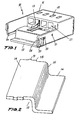
- the connector (10) is formed with a body (11) of noticeably prismatic configuration which minor lateral bases extend as per extensions whose interior face shows near its perimeter support guides or channels (24).
- the body (11), as per a known formula, is volumetrically distributed as per a set of cavities (25) also prismatic, inside which are placed the terminals (13).
- the support (12), see Figure 2, is formed with two planes (14 and 16) related through a wall (15) perpendicular to same and of little height.
- guides (18) which fit with the channels (24) in such a way that once introduced the terminals into the interior of the cavities (25) is placed the support (12) in such a way that the guides (18) slid by the channels (24) until the front edge of the support zone (14) contacts the interior portion of the body (11) of the connector (10).
- the body (11) shows in one of its bases a row of mouths (20) by wich are introduced the corresponding male terminals, not shown in the figures, making contact with the corresponding female terminals (13) situated in the interior of the cavities (25).
- the mouths (20) had been designed in such a way that between their centers the longitudinal axis passing through same show a distance a and b of the same magnitude which in combination with the characteristics of the terminals (13) used allows, as can be seen in Figure 1, that the rear portions of said terminals (13) remain placed over the plane of support or welding (14), allowing with that, as has been said above, firstly that all welding zones remain placed in the same plane, the (14), secondly that the distance between said flat zones, given the configuration of the mouths and the distances between their axis a and b , referred in Figure 3, allows that said rear zones of the terminals (13) keep always a constant distance, by which it will be possible to fully automate the welding operation, given that the means may work always in a flat zone and produce the welding at regular intervals, in time as well as in distance.
- the configuration of the connector (10) above described allows introducing in a first operation the terminals (13) into the cavities (25) for placing then the support (12) with the help of the guides (18) and the channels (24), for proceeding then to the welding operation by any known method but in a fully automated way.
Landscapes
- Engineering & Computer Science (AREA)
- Manufacturing & Machinery (AREA)
- Details Of Connecting Devices For Male And Female Coupling (AREA)
- Multi-Conductor Connections (AREA)
- Connections Effected By Soldering, Adhesion, Or Permanent Deformation (AREA)
Applications Claiming Priority (3)
| Application Number | Priority Date | Filing Date | Title |
|---|---|---|---|
| ES9801891U | 1998-07-15 | ||
| ES009801891U ES1040915Y (es) | 1998-07-15 | 1998-07-15 | Conector perfeccionado con adaptacion de paso. |
| PCT/ES1999/000189 WO2000004605A1 (fr) | 1998-07-15 | 1999-06-23 | Connecteur conçu pour faciliter le soudage de bornes |
Publications (1)
| Publication Number | Publication Date |
|---|---|
| EP1017128A1 true EP1017128A1 (fr) | 2000-07-05 |
Family
ID=8305104
Family Applications (1)
| Application Number | Title | Priority Date | Filing Date |
|---|---|---|---|
| EP99928016A Withdrawn EP1017128A1 (fr) | 1998-07-15 | 1999-06-23 | Connecteur con u pour faciliter le soudage de bornes |
Country Status (5)
| Country | Link |
|---|---|
| EP (1) | EP1017128A1 (fr) |
| JP (1) | JP2002520804A (fr) |
| CA (1) | CA2304182A1 (fr) |
| ES (1) | ES1040915Y (fr) |
| WO (1) | WO2000004605A1 (fr) |
Families Citing this family (4)
| Publication number | Priority date | Publication date | Assignee | Title |
|---|---|---|---|---|
| ES2164027B1 (es) * | 2000-06-21 | 2003-05-16 | Lear Automotive Eeds Spain | Conector de cable plano para soldadura ultrasonica. |
| DE102007008374B4 (de) | 2007-02-21 | 2008-11-20 | Forschungszentrum Karlsruhe Gmbh | Implantierbares System zur Bestimmung des Akkommodationsbedarfes durch Messung der Augapfelorientierung unter Nutzung eines externen Magnetfelds |
| DE102008023726B4 (de) | 2008-05-15 | 2011-01-27 | Karlsruher Institut für Technologie | Implantierbare Vorrichtung zur Herstellung der Akkomodationsfähigkeit unter Nutzung interner Energie |
| DE102009059229A1 (de) | 2009-12-18 | 2011-06-22 | Karlsruher Institut für Technologie, 76131 | Implantierbares System zur Bestimmung des Akkommodationsbedarfs |
Family Cites Families (3)
| Publication number | Priority date | Publication date | Assignee | Title |
|---|---|---|---|---|
| JP3225065B2 (ja) * | 1991-09-17 | 2001-11-05 | ケル株式会社 | 電気コネクタ |
| JP3320450B2 (ja) * | 1992-06-16 | 2002-09-03 | ミネソタ マイニング アンド マニュファクチャリング カンパニー | 表面実装用コネクタ |
| JPH07220780A (ja) * | 1993-12-29 | 1995-08-18 | Whitaker Corp:The | 表面実装型コネクタ |
-
1998
- 1998-07-15 ES ES009801891U patent/ES1040915Y/es not_active Expired - Lifetime
-
1999
- 1999-06-23 CA CA002304182A patent/CA2304182A1/fr not_active Abandoned
- 1999-06-23 EP EP99928016A patent/EP1017128A1/fr not_active Withdrawn
- 1999-06-23 JP JP2000560632A patent/JP2002520804A/ja not_active Withdrawn
- 1999-06-23 WO PCT/ES1999/000189 patent/WO2000004605A1/fr not_active Ceased
Non-Patent Citations (1)
| Title |
|---|
| See references of WO0004605A1 * |
Also Published As
| Publication number | Publication date |
|---|---|
| WO2000004605A1 (fr) | 2000-01-27 |
| ES1040915Y (es) | 1999-11-01 |
| ES1040915U (es) | 1999-06-01 |
| CA2304182A1 (fr) | 2000-01-27 |
| JP2002520804A (ja) | 2002-07-09 |
Similar Documents
| Publication | Publication Date | Title |
|---|---|---|
| US4255009A (en) | Two row electrical connector | |
| US12322917B2 (en) | IDCC connection system and process | |
| EP0306523B1 (fr) | Systeme de retenue et d'alignement de broches de brasage | |
| US4964812A (en) | Wire termination block | |
| EP0817324B1 (fr) | Connecteur électrique pour l'utilisation dans ensembles miniaturisés de densité élevée et de nombre de contacts élevée et méthode de fabrication | |
| US4737117A (en) | Double-row electrical connector and method of making same | |
| US4596436A (en) | Electrical connector housing assembly comprising housing frame containing housing modules | |
| KR100192624B1 (ko) | 전기 커넥터 단자 및 이를 구비한 전기 커넥터의 제조 방법 | |
| EP0820122A2 (fr) | Fabrication de contacts électriques pour des connecteurs de bord de carte | |
| US5281165A (en) | Electrical connector shroud adapted for shorting bar removal | |
| EP0039569B1 (fr) | Connecteur électrique à fiche et douille | |
| WO1979001118A1 (fr) | Connecteur electrique et methode de fabrication d'un faisceau de fils utilisant le connecteur | |
| EP0418857A1 (fr) | Douille à deux points de contact | |
| US6666727B2 (en) | Connector composed of connector socket and mated connector | |
| WO2015164201A1 (fr) | Ensemble connecteur en mezzanine | |
| EP0211496B1 (fr) | Connecteur électrique à double rangée de connexions | |
| EP0279700B1 (fr) | Connecteur électrique (coupé à travers le couvercle) | |
| EP0082697B1 (fr) | Connecteur à contacts multiples | |
| EP1017128A1 (fr) | Connecteur con u pour faciliter le soudage de bornes | |
| EP0018160B1 (fr) | Connecteur électrique de raccordement d'un câble plat multiconducteur | |
| CA1063690A (fr) | Connecteur electrique a percement d'isolant | |
| FI67458B (fi) | Elektriskt kontaktdon med stickkontakt och stickdosa och foerfarande foer dess framstaellning | |
| EP1102352A1 (fr) | Boítier de connexions électrques avec rail de racordement | |
| EP0332363B1 (fr) | Procédé de fonctionnement d'une machine de câblage | |
| CN113270774B (zh) | 短接销、带该短接销的插接连接器和制造该短接销的方法 |
Legal Events
| Date | Code | Title | Description |
|---|---|---|---|
| PUAI | Public reference made under article 153(3) epc to a published international application that has entered the european phase |
Free format text: ORIGINAL CODE: 0009012 |
|
| 17P | Request for examination filed |
Effective date: 19991220 |
|
| AK | Designated contracting states |
Kind code of ref document: A1 Designated state(s): BE DE FR GB IT NL SE |
|
| 17Q | First examination report despatched |
Effective date: 20001204 |
|
| STAA | Information on the status of an ep patent application or granted ep patent |
Free format text: STATUS: THE APPLICATION HAS BEEN WITHDRAWN |
|
| 18W | Application withdrawn |
Withdrawal date: 20011206 |