EP1017131A2 - Connecteur électrique pour un câble coaxial - Google Patents
Connecteur électrique pour un câble coaxial Download PDFInfo
- Publication number
- EP1017131A2 EP1017131A2 EP99123078A EP99123078A EP1017131A2 EP 1017131 A2 EP1017131 A2 EP 1017131A2 EP 99123078 A EP99123078 A EP 99123078A EP 99123078 A EP99123078 A EP 99123078A EP 1017131 A2 EP1017131 A2 EP 1017131A2
- Authority
- EP
- European Patent Office
- Prior art keywords
- carrier
- coaxial cable
- electrical connector
- cover
- cable
- Prior art date
- Legal status (The legal status is an assumption and is not a legal conclusion. Google has not performed a legal analysis and makes no representation as to the accuracy of the status listed.)
- Withdrawn
Links
- 239000004020 conductor Substances 0.000 claims abstract description 23
- 239000012212 insulator Substances 0.000 claims abstract description 15
- 239000007769 metal material Substances 0.000 claims description 10
- 230000000295 complement effect Effects 0.000 claims description 9
- 238000005476 soldering Methods 0.000 claims description 4
- 229910000679 solder Inorganic materials 0.000 description 4
- 239000003989 dielectric material Substances 0.000 description 2
- 239000002184 metal Substances 0.000 description 2
- 238000004519 manufacturing process Methods 0.000 description 1
- 230000013011 mating Effects 0.000 description 1
Images



Classifications
-
- H—ELECTRICITY
- H01—ELECTRIC ELEMENTS
- H01R—ELECTRICALLY-CONDUCTIVE CONNECTIONS; STRUCTURAL ASSOCIATIONS OF A PLURALITY OF MUTUALLY-INSULATED ELECTRICAL CONNECTING ELEMENTS; COUPLING DEVICES; CURRENT COLLECTORS
- H01R24/00—Two-part coupling devices, or either of their cooperating parts, characterised by their overall structure
- H01R24/38—Two-part coupling devices, or either of their cooperating parts, characterised by their overall structure having concentrically or coaxially arranged contacts
- H01R24/40—Two-part coupling devices, or either of their cooperating parts, characterised by their overall structure having concentrically or coaxially arranged contacts specially adapted for high frequency
- H01R24/42—Two-part coupling devices, or either of their cooperating parts, characterised by their overall structure having concentrically or coaxially arranged contacts specially adapted for high frequency comprising impedance matching means or electrical components, e.g. filters or switches
- H01R24/44—Two-part coupling devices, or either of their cooperating parts, characterised by their overall structure having concentrically or coaxially arranged contacts specially adapted for high frequency comprising impedance matching means or electrical components, e.g. filters or switches comprising impedance matching means
-
- H—ELECTRICITY
- H01—ELECTRIC ELEMENTS
- H01R—ELECTRICALLY-CONDUCTIVE CONNECTIONS; STRUCTURAL ASSOCIATIONS OF A PLURALITY OF MUTUALLY-INSULATED ELECTRICAL CONNECTING ELEMENTS; COUPLING DEVICES; CURRENT COLLECTORS
- H01R9/00—Structural associations of a plurality of mutually-insulated electrical connecting elements, e.g. terminal strips or terminal blocks; Terminals or binding posts mounted upon a base or in a case; Bases therefor
- H01R9/03—Connectors arranged to contact a plurality of the conductors of a multiconductor cable, e.g. tapping connections
- H01R9/05—Connectors arranged to contact a plurality of the conductors of a multiconductor cable, e.g. tapping connections for coaxial cables
- H01R9/0518—Connection to outer conductor by crimping or by crimping ferrule
-
- H—ELECTRICITY
- H01—ELECTRIC ELEMENTS
- H01R—ELECTRICALLY-CONDUCTIVE CONNECTIONS; STRUCTURAL ASSOCIATIONS OF A PLURALITY OF MUTUALLY-INSULATED ELECTRICAL CONNECTING ELEMENTS; COUPLING DEVICES; CURRENT COLLECTORS
- H01R2103/00—Two poles
Definitions
- This invention generally relates to the art of electrical connectors and, particularly, to a connector for terminating a coaxial cable.
- a typical coaxial cable includes a center conductive core or conductor surrounded by an insulating or dielectric sheath.
- a conductive shield surrounds the insulating sheath and typically is a metal braid. The shielding braid is surrounded by an outer dielectric tubular cover of the cable.
- the conductive core or conductor of a radio frequency coaxial cable may be very small in diameter. Not only must the conductor of the cable be connected to a signal terminal of the connector, but the shielding braid of the cable must be connected or otherwise engaged with a shell or ground terminal of the connector.
- Such coaxial cable connectors are quite complex to manufacture and are especially difficult to assemble and terminate to the cable, particularly by hand termination. It also is difficult to maintain proper positioning and spacing of the terminals within the connector, itself to ensure a consistent impedance throughout the connector.
- the present invention is directed to solving these various problems by providing a very efficient coaxial cable connector which is very easy to assemble and terminate.
- An object, therefore, of the invention is to provide a new and improved electrical connector for terminating a coaxial cable.
- the cable has at least an inner conductor and an outer conductive shield.
- the connector includes a coaxial cable carrier for holding the coaxial cable.
- the carrier includes a forwardly projecting ground terminal, and the carrier is engaged with the conductive shield of the cable.
- a terminal module including an insulator mounting a forwardly projecting signal terminal, is mountable on the carrier to form a subassembly, with the signal terminal generally parallel to the ground terminal.
- a conductive shielding shell receives the subassembly, with the conductive shell being in engagement with the conductive carrier.
- a cover is mounted on the shell for holding the conductor of the cable in engagement with the signal terminal of the terminal module.
- the coaxial cable carrier is stamped and formed of sheet metal material and includes an elongated base having upstanding side arms forming a cradle for receiving the coaxial cable.
- the base has at least one aperture for soldering the conductive shield of the cable to the carrier through the aperture.
- the conductive shielding shell also is stamped and formed of sheet metal material.
- the signal terminal of the terminal module is insert molded in the insulator of the module to provide precise positioning of the signal terminal.
- the signal terminal has a forward contact end and a flexible terminating end against which the conductor of the cable is biased by the cover.
- the cover is pivotally mounted on the shielding shell.
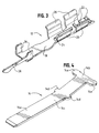
- the electrical connector of the invention includes a terminal module, generally designated 10, which is mountable on a coaxial cable carrier, generally designated 12.
- Terminal module 10 includes a signal terminal, generally designated 14, insert molded within an insulator block 16 which is a one-piece structure molded of dielectric material such as plastic or the like.
- the signal terminal has a forwardly projecting contact end 14a and a rear flexible terminating end 14b. The forward contact end of the terminal projects from a front nose 16a of insulator block 16.
- coaxial cable carrier 12 is stamped and formed of conductive sheet metal material and includes an elongated base 18 having two pairs of upstanding side arms 20 forming a cradle for receiving a coaxial cable, as described hereinafter.
- a plurality of strain relief ribs 22 are formed at the rear end of the carrier.
- a hole 24 is formed in base 18 for soldering the carrier to the shielding braid of the cable trough the hole.
- a pair of front upstanding arms 26 receive front nose 16a of insulator block 16 of terminal module 10. One arm 26 fits into a slot in the front nose 16A and the other arm 26 contacts a side of the front nose opposite the slot.
- a ground terminal 28 projects forwardly of the carrier.
- signal terminal 14 includes forward contact end 14a and rear flexible terminating end 14b.
- the terminal is stamped and formed of conductive sheet metal material.
- a mid-section 14c of the terminal has a pair of outwardly projecting wings 14d.
- the mid-section and the wings are insert molded within insulator block 16, and the wings facilitate rigidly holding the terminal in the insulator block.
- a pair of outwardly projecting locking tabs 14e are formed at the rear of the terminal.
- Figure 2 shows a subassembly, generally designated 30, which is comprised of terminal module 10 and coaxial cable carrier 12. It can be seen that front nose 16a of the insulator block of the terminal module is press fit between front upstanding arms 26 of the carrier, and insulator block 16 of the module sits on top of base 18 of the carder. Ground terminal 28 of the carrier extends along-side of and generally parallel to forwardly projecting contact end 14a of signal terminal 14.
- subassembly 30 comprising terminal module 10 and coaxial cable carrier 12 is assembled to a shielding shell, generally designated 32, by inserting the subassembly into the shell in the direction of arrow "A".
- a side elevational view of subassembly 30 also is shown in Figure 5.
- Shielding shell 32 is a one-piece structure stamped and formed of conductive sheet metal material.
- the shell has a closed front end 34 within which contact end 14a of signal terminal 14 and ground terminal 28 of carrier 12 are disposed, with the terminals being completely surrounded by the closed front end of the shell.
- the rear end of shell 32 is generally U-shaped and includes a pair of spaced, upstanding side walls 36.
- Each side wall has a pair of latch apertures 38 and an interlocking notch 40.
- Each side wall also has a pivot hole 42 near the front top corner of the side wall.
- a cover is unitarily molded of dielectric material such as plastic or the like.
- the cover has a pair of pivot trunions 46 on opposite sides thereof that snap into pivot holes 42 of shell 32 to pivotally mount the cover to the shell.
- a U-shaped strain relief flange 48 is formed at the opposite end of the cover and will become aligned with strain relief ribs 22 of coaxial cable carrier 12 to clamp the cable therebetween.
- the cover has a pair of chamfered latch bosses 50 on each opposite side thereof for snapping into locking engagement within latch apertures 38 in side walls 36 of the shell.
- the cover has an interlocking boss 52 on each opposite side thereof for positioning into interlocking notches 40 in side walls 36 of the shell.
- a cross flange 54 of the cover engages and biases the conductive core of the coaxial cable against flexible terminating end 14b of signal terminal 14. This moves the flexible terminating end 14b to a location parallel to the ground terminal ensuring a consistent impedance through that portion of the terminal.
- a pair of locking prongs 56 are formed at opposite ends of cross flange 54 of the cover for locking behind locking tabs 14e (Fig. 4) of the signal terminal.
- Figure 7 shows the completely assembled electrical connector, generally designated 66, of the invention with cover 44 pivotally mounted to shell 32 and with the cover in its open position.
- Figure 6 also shows a coaxial cable, generally designated 68, in a prepared condition.
- the cable includes an outer dielectric tubular cover 70 about a conductive shield in the form of a metal braid 72.
- the braid surrounds an inner dielectric sheath 74 which, in turn, surrounds a center conductive core or conductor 76 of the cable. It can be seen that outer cover 70 has been cut back to expose shielding braid 72.
- the braid and inner dielectric 74 have been cut back to expose conductor 76.
- the cable is assembled to connector 66 in the direction of arrow "B", with cover 44 in open condition.
- outer dielectric cover 70 is aligned with strain relief ribs 22 (Fig. 3) of carrier 12.
- Shielding braid 72 is aligned with solder hole 24 of the carrier.
- Conductor 76 of the cable is aligned with flexible terminating end 14b of signal terminal 14.
- cover 44 is pivoted in the direction of arrow "C" (Fig. 6) to its closed and latched condition shown in Figures 7-9.
- chamfered latch bosses 50 of the cover snap into locking engagement within latch apertures 38 of shell 32, while interlocking bosses 52 move into interlocking notches 40 of the shell.
- strain relief flange 48 of the cover clamps the outer dielectric cover of the cable against strain relief ribs 22 (Fig. 3) of carrier 12, and cross flange 54 of the cover biases the conductor of the cable against flexible terminating end 14b of signal terminal 14.
- the bottom of shell 32 has a solder hole 78 aligned with solder hole 24 in carrier 12 to solder the shielding braid 72 of the cable to the conductive carrier which is in engagement with conductive shell 32.
- Figure 9 also shows that the bottom of the stamped and formed shell 32 is provided with a shear form 80 to ensure correct impedance by supporting the coaxial cable cater 12 a predetermined distance from the signal terminal 14 and to enhance engagement of the conductive shell with the conductive coaxial cable carrier 12.
- ground terminal 28 of carrier 12 and forward contact end 14a of signal terminal 14 extend generally parallel within and are surrounded by closed front end 34 of the shell.
- the shielding braid 72 electrically coupled to conductive carrier 12 which, in turn, is in engagement with conductive shielding shell 32, the connector provides a stable ground potential with a consistent impedance through the connector and avoids electromagnetic interference at the terminated interface of the cable.
Landscapes
- Multi-Conductor Connections (AREA)
- Coupling Device And Connection With Printed Circuit (AREA)
- Connections Effected By Soldering, Adhesion, Or Permanent Deformation (AREA)
- Details Of Connecting Devices For Male And Female Coupling (AREA)
Applications Claiming Priority (2)
| Application Number | Priority Date | Filing Date | Title |
|---|---|---|---|
| US09/222,234 US6065998A (en) | 1998-12-29 | 1998-12-29 | Electrical connector for coaxial cable |
| US222234 | 1998-12-29 |
Publications (2)
| Publication Number | Publication Date |
|---|---|
| EP1017131A2 true EP1017131A2 (fr) | 2000-07-05 |
| EP1017131A3 EP1017131A3 (fr) | 2002-01-30 |
Family
ID=22831417
Family Applications (1)
| Application Number | Title | Priority Date | Filing Date |
|---|---|---|---|
| EP99123078A Withdrawn EP1017131A3 (fr) | 1998-12-29 | 1999-11-22 | Connecteur électrique pour un câble coaxial |
Country Status (6)
| Country | Link |
|---|---|
| US (1) | US6065998A (fr) |
| EP (1) | EP1017131A3 (fr) |
| JP (1) | JP3104176B2 (fr) |
| MY (1) | MY130878A (fr) |
| SG (1) | SG82022A1 (fr) |
| TW (1) | TW431702U (fr) |
Cited By (1)
| Publication number | Priority date | Publication date | Assignee | Title |
|---|---|---|---|---|
| CN1320699C (zh) * | 2002-06-06 | 2007-06-06 | 日本压着端子制造株式会社 | 外壳加工夹具 |
Families Citing this family (19)
| Publication number | Priority date | Publication date | Assignee | Title |
|---|---|---|---|---|
| JP3645440B2 (ja) * | 1999-02-05 | 2005-05-11 | 矢崎総業株式会社 | 同軸コネクタの端末処理構造及び端末処理方法 |
| US6186828B1 (en) * | 1999-08-30 | 2001-02-13 | Molex Incorporated | Electrical connector including coaxial cable management system |
| JP3607147B2 (ja) * | 1999-12-14 | 2005-01-05 | 矢崎総業株式会社 | 電線と端子の接続方法及び端子接続装置 |
| JP2002042990A (ja) * | 2000-07-21 | 2002-02-08 | Sumitomo Wiring Syst Ltd | シールド端子 |
| US6746277B2 (en) * | 2001-12-05 | 2004-06-08 | Tyco Electronics Corporation | Coaxial cable connector |
| US6572410B1 (en) * | 2002-02-20 | 2003-06-03 | Fci Americas Technology, Inc. | Connection header and shield |
| JP4124760B2 (ja) * | 2003-12-22 | 2008-07-23 | モレックス インコーポレーテッド | 同軸ケーブル用コネクタ及びケーブル保持具 |
| US6988911B2 (en) * | 2004-03-02 | 2006-01-24 | Tyco Electronics Corporation | Coaxial cable connector with improved shielding |
| SE530315C2 (sv) * | 2006-09-22 | 2008-04-29 | Mt Skellefteaa Memoteknik Ab | Anordning för elektrisk jordning av en isolerad kabel |
| US7785118B2 (en) * | 2007-07-31 | 2010-08-31 | Tyco Electronics Corporation | Coaxial cable connector having a compensating tab |
| JP5033660B2 (ja) * | 2008-01-30 | 2012-09-26 | 矢崎総業株式会社 | 同軸コネクタ及び同軸コネクタの組み付け方法 |
| EP2184812A1 (fr) * | 2008-11-06 | 2010-05-12 | Hon Hai Precision Industry Co., Ltd. | Ensemble connecteur d'extrémité de câble |
| USD717159S1 (en) * | 2012-02-15 | 2014-11-11 | Memoteknik Sweden AB | Cable clamp |
| EP3089272A1 (fr) * | 2015-04-29 | 2016-11-02 | AGC Glass Europe | Panneau de vitrage présentant un connecteur électroconducteur |
| TWI608678B (zh) * | 2016-07-01 | 2017-12-11 | 春源科技(深圳)有限公司 | Rf線端連接器與同軸線纜的連接方法及其使用的內部端子 |
| CN107247164A (zh) * | 2017-07-14 | 2017-10-13 | 许继(厦门)智能电力设备股份有限公司 | 电缆终端对接模块及其装配方法 |
| TWI735120B (zh) * | 2019-12-30 | 2021-08-01 | 李雅惠 | 電連接器及其組裝方法 |
| DE102020105994A1 (de) * | 2020-03-05 | 2021-09-09 | Te Connectivity Germany Gmbh | Robustes, hochfrequenz-geeignetes elektrisches Terminal |
| JP7014252B2 (ja) * | 2020-03-30 | 2022-02-01 | 住友電装株式会社 | シールド端子及びシールドコネクタ |
Family Cites Families (8)
| Publication number | Priority date | Publication date | Assignee | Title |
|---|---|---|---|---|
| US4708414A (en) * | 1987-01-30 | 1987-11-24 | Albert Lam | Electric wire connector for coaxial cable |
| US4946392A (en) * | 1988-08-09 | 1990-08-07 | Amp Incorporated | Coaxial connector in a housing block |
| JPH031460A (ja) * | 1989-05-30 | 1991-01-08 | Amp Japan Ltd | 電気コネクタ |
| JP2906469B2 (ja) * | 1989-08-20 | 1999-06-21 | オムロン株式会社 | シールド線用コネクタ |
| US5267868A (en) * | 1992-10-01 | 1993-12-07 | Molex Incorporated | Shielded electrical connector assemblies |
| JP3356476B2 (ja) * | 1993-02-23 | 2002-12-16 | 松下電工株式会社 | Tv同軸プラグ |
| JPH078961U (ja) * | 1993-07-14 | 1995-02-07 | 日本エー・エム・ピー株式会社 | 同軸ケーブル用コネクタ |
| US5304069A (en) * | 1993-07-22 | 1994-04-19 | Molex Incorporated | Grounding electrical connectors |
-
1998
- 1998-12-29 US US09/222,234 patent/US6065998A/en not_active Expired - Fee Related
-
1999
- 1999-09-30 TW TW088216533U patent/TW431702U/zh not_active IP Right Cessation
- 1999-09-30 SG SG9904860A patent/SG82022A1/en unknown
- 1999-11-22 EP EP99123078A patent/EP1017131A3/fr not_active Withdrawn
- 1999-12-22 JP JP11364302A patent/JP3104176B2/ja not_active Expired - Fee Related
- 1999-12-28 MY MYPI99005765A patent/MY130878A/en unknown
Cited By (1)
| Publication number | Priority date | Publication date | Assignee | Title |
|---|---|---|---|---|
| CN1320699C (zh) * | 2002-06-06 | 2007-06-06 | 日本压着端子制造株式会社 | 外壳加工夹具 |
Also Published As
| Publication number | Publication date |
|---|---|
| JP2000195585A (ja) | 2000-07-14 |
| MY130878A (en) | 2007-07-31 |
| SG82022A1 (en) | 2001-07-24 |
| JP3104176B2 (ja) | 2000-10-30 |
| EP1017131A3 (fr) | 2002-01-30 |
| TW431702U (en) | 2001-04-21 |
| US6065998A (en) | 2000-05-23 |
Similar Documents
| Publication | Publication Date | Title |
|---|---|---|
| US6065998A (en) | Electrical connector for coaxial cable | |
| JP4578522B2 (ja) | 低インダクタンスシールドコネクタ | |
| EP0118168B2 (fr) | Connecteur électrique enfichable et prise assortie | |
| US6582252B1 (en) | Termination connector assembly with tight angle for shielded cable | |
| US4611878A (en) | Electrical plug connector | |
| US4838811A (en) | Modular connector with EMI countermeasure | |
| US6929512B2 (en) | Cable end connector assembly with a shield device | |
| KR102774577B1 (ko) | 접촉 조립체의 탄성 암을 스터빙으로부터 보호하기 위한 보호 부재 | |
| US20140187087A1 (en) | Rf cable connector | |
| EP0624928B1 (fr) | Ensemble connecteur électrique blindé | |
| US6966797B2 (en) | High-speed cable assembly | |
| US6250953B1 (en) | Connector assembly for coaxial cables | |
| EP0542075B1 (fr) | Procédé pour terminer un connecteur électrique miniature coaxial et un connecteur terminé selon le procédé | |
| US5711676A (en) | Vertically mounted cable plug | |
| JPH07192819A (ja) | 同軸コネクタ | |
| US6217374B1 (en) | Electrical connector with wire management system | |
| JP3425634B2 (ja) | 高速ケーブル用のシールド終端機構を備えた電気コネクタ | |
| US5186656A (en) | Miniature coaxial electrical connector | |
| CN110808491A (zh) | 电连接器组件 | |
| EP0951092A2 (fr) | Connecteur électrique pour des câbles coaxiaux | |
| US20060246783A1 (en) | Electrical connector assembly | |
| US6106334A (en) | Shielded cable connector | |
| EP0510264B1 (fr) | Système de connexion pour des câbles coaxiales | |
| GB2313719A (en) | Coaxial connector for pcb |
Legal Events
| Date | Code | Title | Description |
|---|---|---|---|
| PUAI | Public reference made under article 153(3) epc to a published international application that has entered the european phase |
Free format text: ORIGINAL CODE: 0009012 |
|
| AK | Designated contracting states |
Kind code of ref document: A2 Designated state(s): AT BE CH CY DE DK ES FI FR GB GR IE IT LI LU MC NL PT SE |
|
| AX | Request for extension of the european patent |
Free format text: AL;LT;LV;MK;RO;SI |
|
| PUAL | Search report despatched |
Free format text: ORIGINAL CODE: 0009013 |
|
| AK | Designated contracting states |
Kind code of ref document: A3 Designated state(s): AT BE CH CY DE DK ES FI FR GB GR IE IT LI LU MC NL PT SE |
|
| AX | Request for extension of the european patent |
Free format text: AL;LT;LV;MK;RO;SI |
|
| 17P | Request for examination filed |
Effective date: 20020619 |
|
| STAA | Information on the status of an ep patent application or granted ep patent |
Free format text: STATUS: THE APPLICATION HAS BEEN WITHDRAWN |
|
| 18W | Application withdrawn |
Withdrawal date: 20020821 |