EP1017133A2 - Elektrisches Verbindergehäuse - Google Patents
Elektrisches Verbindergehäuse Download PDFInfo
- Publication number
- EP1017133A2 EP1017133A2 EP99403196A EP99403196A EP1017133A2 EP 1017133 A2 EP1017133 A2 EP 1017133A2 EP 99403196 A EP99403196 A EP 99403196A EP 99403196 A EP99403196 A EP 99403196A EP 1017133 A2 EP1017133 A2 EP 1017133A2
- Authority
- EP
- European Patent Office
- Prior art keywords
- electrically conductive
- conductive elements
- electrical
- connector housing
- bus bars
- Prior art date
- Legal status (The legal status is an assumption and is not a legal conclusion. Google has not performed a legal analysis and makes no representation as to the accuracy of the status listed.)
- Withdrawn
Links
Images



Classifications
-
- H—ELECTRICITY
- H02—GENERATION; CONVERSION OR DISTRIBUTION OF ELECTRIC POWER
- H02B—BOARDS, SUBSTATIONS OR SWITCHING ARRANGEMENTS FOR THE SUPPLY OR DISTRIBUTION OF ELECTRIC POWER
- H02B1/00—Frameworks, boards, panels, desks, casings; Details of substations or switching arrangements
- H02B1/20—Bus-bar or other wiring layouts, e.g. in cubicles, in switchyards
- H02B1/207—Cross-bar layouts
-
- H—ELECTRICITY
- H01—ELECTRIC ELEMENTS
- H01R—ELECTRICALLY-CONDUCTIVE CONNECTIONS; STRUCTURAL ASSOCIATIONS OF A PLURALITY OF MUTUALLY-INSULATED ELECTRICAL CONNECTING ELEMENTS; COUPLING DEVICES; CURRENT COLLECTORS
- H01R9/00—Structural associations of a plurality of mutually-insulated electrical connecting elements, e.g. terminal strips or terminal blocks; Terminals or binding posts mounted upon a base or in a case; Bases therefor
- H01R9/22—Bases, e.g. strip, block, panel
- H01R9/24—Terminal blocks
-
- H—ELECTRICITY
- H05—ELECTRIC TECHNIQUES NOT OTHERWISE PROVIDED FOR
- H05K—PRINTED CIRCUITS; CASINGS OR CONSTRUCTIONAL DETAILS OF ELECTRIC APPARATUS; MANUFACTURE OF ASSEMBLAGES OF ELECTRICAL COMPONENTS
- H05K1/00—Printed circuits
- H05K1/02—Details
- H05K1/0286—Programmable, customizable or modifiable circuits
- H05K1/0287—Programmable, customizable or modifiable circuits having an universal lay-out, e.g. pad or land grid patterns or mesh patterns
- H05K1/0289—Programmable, customizable or modifiable circuits having an universal lay-out, e.g. pad or land grid patterns or mesh patterns having a matrix lay-out, i.e. having selectively interconnectable sets of X-conductors and Y-conductors in different planes
-
- Y—GENERAL TAGGING OF NEW TECHNOLOGICAL DEVELOPMENTS; GENERAL TAGGING OF CROSS-SECTIONAL TECHNOLOGIES SPANNING OVER SEVERAL SECTIONS OF THE IPC; TECHNICAL SUBJECTS COVERED BY FORMER USPC CROSS-REFERENCE ART COLLECTIONS [XRACs] AND DIGESTS
- Y10—TECHNICAL SUBJECTS COVERED BY FORMER USPC
- Y10S—TECHNICAL SUBJECTS COVERED BY FORMER USPC CROSS-REFERENCE ART COLLECTIONS [XRACs] AND DIGESTS
- Y10S439/00—Electrical connectors
- Y10S439/949—Junction box with busbar for plug-socket type interconnection with receptacle
Definitions
- the present invention relates to electrical connector housings used for example in automobiles. More particularly, the electrical connector housing according to the invention is used as a junction box that contains a plurality of branch circuits and on which can be mounted electrical relays, fuses and electrical connectors.
- the circuit configuration can be standardized for making it easier to form the circuitry and respond to changes.
- Automobiles are packed with different kinds of electrical parts or electrical apparatuses, depending on their grade, type or model. Usually, the higher is their grade, the greater is the number of circuits used. In order to respond to the variations in this number of circuits as a function of the vehicle grades, it is preferable to standardize the structure of electrical connector housings, the bus bars they contain, and the connector assemblies received by the connector receptacles of electrical connector housings. In this way, these elements can be used for all automobile grades and thus gain a wider use. By contrast, the number of external terminals to be contained in a connector assembly is determined by the automobile's grade, so that one connector assembly contains only the number of external terminals necessary for a particular grade.
- the electrical connector housing, its bus bars and the connector assembly may be structurally standardized, the only difference being that circuits for high comfort apparatuses are not provided for in the connector assembly of low grade cars.
- the low-grade connector assembly is not provided with a sufficient number of outer terminals to connect with all the available bus bars contained in an electrical connector housing.
- FIG. 1 shows an electrical connector housing commonly used in automobiles.
- Such an electrical connector housing is in the form of a case consisting of a lower case 1 and an upper case 2.
- the case contains bus bars 3 and insulating plates 4 stacked in alternation.
- the bus bar 3 is made by stamping out a given form of circuitry from an electrically conductive plate, and comprises a series of projecting tabs. Relays, fuses or connectors are mounted in fitting units formed on the lower case 1 and/or the upper case 2.
- the tabs 3a are then connected to electrical relays, fuses or connectors via transit terminals (not shown in the figures).
- coated conductive wires are used instead of bus bars 3. Cramping members are then press-fitted to the coated conductive wires, and the latter are thus connected to relays, fuses or connectors via transit terminals.
- bus bars When bus bars are used, their design has to be changed each time the routings need to be modified.
- the circuitry modification calls for a change of the molds used for bus bar manufacturing and thus incurs high costs. It is also difficult to respond quickly to circuit modifications or additions.
- coated conductive cables or wires and cramping members are used, the coated conductive cables have to be wired along a given routing.
- guiding means have to be provided on insulating plates or on the inner surface of the case. Accordingly, when a circuit is modified or added, the insulating plates and the case, as well as the molds for making them, have to be changed. The consequent need to make a new mold also incurs a cost, just as in the case of bus bars.
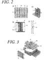
- FIG. 2 (A), (B), (C) and (D) show branch connection boxes designed by the present inventors and published as Japanese Utility Model HEI-5-55718.
- the branch connection boxes have two cases 6 and 6 of the same configuration, each including the same number of connector receptacles 5a and corresponding rear portions opposite them.
- the cases 6 contain a plurality of bus bars 7 each one having the same bifurcate fork-shape and being symmetrical about its longitudinal center axis.
- the two cases 6 and 6 are then stacked back to back so that the connector receptacles 5a face in opposite directions.
- the bus bars 7 are then mounted into the cases 6 and 6 such as to be aligned parallel to one another.
- electrical cables 8 are cramped into the center portion of bifurcate fork shape bus bars 7, so that the bus bars 7 and the electrical cables 8 are electrically connected.
- FIG. 3 shows an electrical connection box disclosed in US Patent 5057026.
- bus bars 9 have a fixed narrow width, and are arranged in parallel.
- the bus bars 9 are provided at given positions with tabs 9a including cramping blades.
- Electrical cables 10 are aligned in a direction perpendicular to the bus bars 9 and connected thereto by pushing down the cramping blades.
- Bus bars 9 and electrical cables 10 thus form a planar circuit stackable on an insulating plate 11, and a plurality of such units are formed into a layered structure.
- a connector assembly 12 is arranged nearby alongside the layered structure. The layers of bus bars 9 are then connected to one another through the connector assembly 12.
- a connector assembly is fitted into a corresponding connector receptacle 5a.
- the connector assembly is not provided with a sufficient number of outside terminals, as is the case of low-grade connector assemblies, a considerable number of bus bars 7 may be left unconnected to any outside terminal and thus not used as circuits. Further, the space for containing connectors is limited, so that, when the number of circuits is increased, the width of the case must be broadened. It then becomes more difficult to produce higher density circuitry.
- bus bars 9 are determined beforehand, and the bus bars are aligned in parallel at given positions.
- the bus bars 9 are then connected to electrical cables by cramping to form circuits. This process requires several process steps and many connection sites, making production complex. Besides, as a connector assembly 12 is needed for connecting the layers of bus bars 9, specific parts have to be prepared. Such complicated process steps and the provision of specific parts incur a high production cost.
- electrically conductive elements for forming all circuits may be made of the same material, so making it simpler and cheaper to produce circuit materials. Furthermore, it is easy to modify or add circuits, assembly work is simplified, and the number of parts is reduced.
- an electrical connector housing comprising a plurality of unit circuits.
- the plurality of unit circuits are comprised of first electrically conductive elements made of the same material and formed into the shape of a long strip with narrow width.
- the first electrically conductive elements are arranged in parallel at a given interval, and connected respectively to an electrical part, such as an electrical relay, fuse or connector, through second electrically conductive elements.
- the second electrically conductive elements are arranged in a direction substantially perpendicular to the length direction of the first electrically conductive elements, thereby forming intersection faces including contact points between the first and the second electrically conductive elements.
- the first electrically conductive elements and the second electrically conductive elements are made of the same material. Further, the first electrically conductive elements have the same length, whereas the second electrically conductive elements have a length varying as a function of the distance between the electrical part and the unit circuit, and the second electrically conductive elements are each used after having been cut out into a given length.
- At least the first electrically conductive elements or the second electrically conductive elements have an insulating film adhered or coated thereon on at least the intersection face including the contact points, and the insulating film is stripped off at the contact points so as to form electrical contact points between the first and the second electrically conductive elements. Thereafter, the electrical contact points are bonded.
- an electrical connector housing wherein the plurality of unit circuits are stacked in layers, and the electrical part such as an electrical relay, fuse or connector is mounted sideways onto each of the layers comprising the plurality of unit circuits, such that the second electrically conductive elements cross the first electrically conductive elements at substantially right angles, and are connected thereto.
- the first and the second electrically conductive elements may be comprised of bus bars.
- the first electrically conductive elements or the second electrically conductive elements adhered or coated with an insulating film on at least the intersection faces including the contact points may be comprised of electrical wires, or a flexible printed circuit whose electrically conductive elements comprise copper foils or bare conductive wires.
- a unit circuit is defined as an electrically conductive element, a terminal of which is connected to a relay, fuse or connector. There is therefore no need to connect these unit circuits to one another. Accordingly, the connector assembly 12 for connecting bus bars 9 therebetween, shown in FIG. 3, is no longer needed.
- the corresponding first electrically conductive element arranged in parallel to other elements, may be removed or added. Thereafter, a newly arranged circuit may be prepared and connected to a given relay, fuse or connector through a perpendicularly-arranged second electrically conductive element. Circuit alterations or additions can thus easily be made.
- the first electrically conductive elements used for unit circuits have the same length and are arranged in parallel.
- the first electrically conductive elements are connected to electrical parts such as electrical relays, fuses or connectors through perpendicularly-arranged second electrically conductive elements.
- the length of each of second electrically conductive element varies depending on the distance between the unit circuit and an electrical part to which it is to be connected.
- the first electrically conductive elements used for unit circuits and the second electrically conductive elements used for connecting to electrical parts are made of the same material.
- the second electrically conductive elements are applied after they have been prepared by cutting off the material at a given length.
- the first electrically conductive elements disposed in parallel as unit circuits, and the second electrically conductive elements for connecting to electrical parts arranged perpendicular thereto, are made of the same material. Furthermore, the first electrically conductive elements can be made into the same length by simply cutting off the same material at a fixed specific length. Likewise, the second electrically conductive elements can be prepared by simply cutting off different lengths of the same material. Accordingly, circuit elements can be prepared very easily at low cost.
- the first electrically conductive elements used for unit circuits, and the second electrically conductive elements for connecting to electrical parts may be formed for instance by bus bars or electrical wires or cables, as well as by flexible printed circuits (FPCs), whose conductive portions consist of copper foils or bare conductive wires or cables.
- FPCs flexible printed circuits
- bus bars When, typically, bus bars are used as a first and a second electrically conductive element and intersected with each other, at least one of those bus bars is covered with an insulating coating at their intersection face. Subsequently, the bus bars are stripped of insulating coatings at their contact sites, and are bonded by resistance, ultrasonic or laser welding, soldering or by direct binding means such as riveting. They are thus connected to each other.
- the first electrically conductive elements used for unit circuits and the second electrically conductive elements for connecting to electrical parts may be electrical wires or cables.
- both electrical wires may be connected by using cramping members serving as electrical terminals.
- insulating coatings are stripped off at the contact points, so that copper foils or the conductive wire core are exposed for subsequent welding.
- the above unit circuits may be stacked vertically so as to form layers. Electrical parts such as relays, fuses and connectors, which are to be mounted sideways into the electrical connector housing, may then be connected to the first electrically conductive elements of the unit circuits. The latter are assembled on each layer, such that second electrically conductive elements for connecting to electrical parts cross the first electrically conductive elements substantially at right angles.
- FIG. 4 is a view of typical circuitry included in a known electrical connector housing.
- C1 and C2 indicate connectors mounted in a connector receptacle provided at a first side (X side) of the case consisting of a lower case and an upper case
- C3 and C4 represent connectors mounted in a connector receptacle provided at a second side (Y side) of the case.
- R represents a relay mounted in a relay receptacle provided at the X side of the case
- F1 and F2 represent fuses mounted in a fuse receptacle provided at the Y side of the case.
- the unit circuits may be defined as the circuits having one end connected to a first relay, fuse or connector, respectively, and the other end connected to a second relay, fuse or connector.
- circuit a has one end connected to a relay R, and the other end that is divided into two branches, one of which is routed to fuse F1 and the other to fuse F2.
- Circuit b has one end connected to connector C3 and the other end connected to relay R.
- Circuit c has one end connected to connector C4 and the other end connected to relay R.
- Circuit d has one end connected to connector C4 and the other end connected to connector C2.
- both ends are connected to either a connector, a relay or a fuse.
- Unit circuits a to g are comprised of first electrically conductive elements, e.g., bus bars 20a to 20g, each of which has the same length with a narrow width.
- the bus bars 20a to 20g are arranged in parallel at a given pitch, and are contained in an electrical connector housing consisting of a lower case 25 and an upper case 26.
- the lengths of bus bars 20a to 20g aligned in parallel are disposed substantially perpendicular to the direction in which a connector, relay or fuse is mounted.
- the second electrically conductive elements for connecting to electrical parts may be made of the same bus bar material as the one used for bus bars 20a to 20g serving as unit circuits. This material is then cut off at a required length to yield bus bars 22a to 22o.
- bus bars 22a to 22o are connected to a respective unit circuit at one end.
- bus bars may be connected to a unit circuit at a middle portion of their length, as in the case of bus bars 22g and 22l.
- each of bus bars 20a to 20g may be adhered or coated with an insulating film 21.
- the insulating film 21 is then locally cut away at the sites where bus bars 20a to 20g intersect with bus bars 22a to 22o; at these interconnections, bus bars 20a to 20g are led to a connector, relay or fuse. In such a case, bus bars 22a to 22o may not be adhered nor coated with any insulating film.
- bus bars 22a to 22o - instead of bus bars 20a to 20g - may be adhered or coated with an insulating film. Their connecting sites with bus bars 20a to 20g may then be stripped of the insulating film. In such a case, the bus bars 20a to 20g for unit circuits may not be adhered nor coated with any insulating film.
- bus bars 22a to 22o for connecting to electrical parts are arranged to cross over bus bars 20a to 20g substantially at a right angle, with the insulating film 21 interposed therebetween.
- the length of each of bus bars 22a to 22o may be different, they are aligned parallel to one another.
- the insulating film 21 is then removed from each of bus bars 20a to 20g at their intersection face with bus bars 22a to 22o.
- An end portion of each of bus bars 22a to 22o (except for some bus bars such as 22g or 22l shown in FIG. 6 as an example) is then put into contact with the corresponding exposed face portion of bus bars 20a to 20g.
- bus bars 22g and 22l their middle portions are connected with bus bars 20a and 20d in the same manner, respectively. As shown in FIG. 7, both portions are then bonded by resistance welding 27 and connected together. Bus bars 22g and 22l are set to be long enough to span across bus bars 20a to 20g and their middle portion is resistance-welded to the insulating film-free portion of bus bars 20a and 20d, respectively.
- the technique for connecting bus bars 20a to 20g to bus bars 22a to 22o is not limited to the above-mentioned resistance welding, but also includes ultrasonic welding, laser welding, soldering or riveting etc.
- each of bus bars 22a to 22o is connected either to connector C1, C2, C3 or C4, or to relay R, or to fuse F1 or F2.
- FIG. 8 shows a second embodiment of the present invention.
- the bus bars may be divided and loaded onto different layers, the layers being subsequently superposed on one another.
- insulating plates 28 are interposed between different layers.
- bus bars 20a to 20g used as unit circuits and bus bars 22a to 22o used for connecting to electrical parts are coated with insulating films, the interposition of insulating plates 28 may not be required.
- FIGS. 9A and 9B show a third embodiment in which first electrically conductive elements used as unit circuits, and second electrically conductive elements used for connecting to electrical parts, are both comprised of coated conductive wires connected by means of cramping members 30.
- the cramping members 30 each have an L-shaped horizontal cross-section (viewed from the top, as depicted in FIG. 9B). They may have a different length of cross-section and include at their bottom portion slots 30b provided with cramping blades 30a.
- the cramping blades 30a connect the first coated conductive wires w1 (used as unit circuits) to the second coated conductive wires w2 (used for connecting to electrical parts) by applying a downward pressing force.
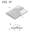
- FIGS. 10A and 10B show a fourth embodiment, in which an FPC 43 serves to form the first electrically conductive elements used as unit circuits, and the second electrically conductive elements used for connecting to electrical parts.
- the FPC 43 is prepared by arranging copper foils or bare conductive wires in parallel to form electrically conductive elements 40, and by coating both faces thereof with insulating films 41 and 42.
- the electrically conductive elements 40 having the same length are formed as an FPC 43, and the corresponding FPC 43 is cut out in rectangular shapes. Further, the insulating films are cut away at the connection sites.
- the FPC 43 is cut off so that each of electrically conductive elements 40 has the desired length.
- the first and the second electrically conductive elements 40 are bonded by resistance welding or the like, and are thus connected to each other.
- an electrical connector housing when an electrical connector housing contains several layers, the latter may comprise different types of circuitry, depending on the intensity of the electric current flowing in the circuitry.
- the housing may contain a first layer wired with bus bars, a second layer wired with electrical wires or cables, and a third layer wired with FPC.
- the electrically conductive elements used as unit circuits, and those used for connecting to electrical parts may not necessarily be made of the same material.
- the first electrically conductive elements used as unit circuits may be formed from an FPC, whereas the second electrically conductive elements used for connecting to electrical parts may be electrical wires or cables. The end portion of electrical wires or cables may then be stripped of insulating films, and the conductive portion thus exposed may be welded to the conductive portion of the FPC.
- unit circuits are prepared by initially arranging fixed lengths of first electrically conductive elements in parallel.
- second electrically conductive elements may simply be set up transversally to the first electrically conductive elements substantially at a right angle.
- an electrically conductive element as unit circuit may simply be removed or added, and the modified or added element can easily be connected to an electrical part through a second electrically conductive element. Electrically conductive elements can thus be modified or added simply. Moreover, circuit addition does not require a large space. Therefore, the electrical connector housing of the invention can be kept reasonably small.
- the electrical connector housing may have a multi-layered structure, connections between layers are not necessary, so that the number of parts can be reduced.
- electrically conductive elements used as unit circuits and those used for connecting to electrical parts can be made of the same material. Accordingly, these elements can be prepared by simply cutting this material into given lengths of element. They can thus be produced easily and at a low cost. The cost reduction obtained by virtue of this manufacturing method is very large.
Landscapes
- Engineering & Computer Science (AREA)
- Microelectronics & Electronic Packaging (AREA)
- Power Engineering (AREA)
- Connection Or Junction Boxes (AREA)
- Connections By Means Of Piercing Elements, Nuts, Or Screws (AREA)
- Details Of Connecting Devices For Male And Female Coupling (AREA)
Applications Claiming Priority (2)
| Application Number | Priority Date | Filing Date | Title |
|---|---|---|---|
| JP36143198 | 1998-12-18 | ||
| JP10361431A JP2000182682A (ja) | 1998-12-18 | 1998-12-18 | 電気接続箱 |
Publications (2)
| Publication Number | Publication Date |
|---|---|
| EP1017133A2 true EP1017133A2 (de) | 2000-07-05 |
| EP1017133A3 EP1017133A3 (de) | 2000-07-19 |
Family
ID=18473553
Family Applications (1)
| Application Number | Title | Priority Date | Filing Date |
|---|---|---|---|
| EP99403196A Withdrawn EP1017133A3 (de) | 1998-12-18 | 1999-12-17 | Elektrisches Verbindergehäuse |
Country Status (4)
| Country | Link |
|---|---|
| US (1) | US6290509B1 (de) |
| EP (1) | EP1017133A3 (de) |
| JP (1) | JP2000182682A (de) |
| CN (1) | CN1099726C (de) |
Cited By (4)
| Publication number | Priority date | Publication date | Assignee | Title |
|---|---|---|---|---|
| WO2006032742A3 (fr) * | 2004-09-17 | 2006-10-26 | Ind S | Procede de distribution repartie de l'energie electrique |
| US7294520B2 (en) | 2003-02-14 | 2007-11-13 | Osram Opto Semiconductors Gmbh | Method for fabricating a plurality of semiconductor bodies, and electronic semiconductor body |
| EP2276331A1 (de) * | 2009-07-13 | 2011-01-19 | Delphi Technologies, Inc. | Kabelsatz und Verfahren zur Herstellung eines Kabelsatzes |
| EP2355259A3 (de) * | 2010-01-28 | 2017-12-13 | Yazaki Corporation | Elektrischer Verteilerkasten |
Families Citing this family (27)
| Publication number | Priority date | Publication date | Assignee | Title |
|---|---|---|---|---|
| JP3785276B2 (ja) * | 1998-09-10 | 2006-06-14 | 矢崎総業株式会社 | 電気接続箱 |
| JP2001035616A (ja) * | 1999-07-21 | 2001-02-09 | Sumitomo Wiring Syst Ltd | ワイヤハーネス用ジョイントコネクタ |
| JP3446672B2 (ja) * | 1999-07-30 | 2003-09-16 | 住友電装株式会社 | 電気接続箱 |
| JP3536016B2 (ja) | 1999-08-17 | 2004-06-07 | 古河電気工業株式会社 | 配線基板とこの配線基板を用いた電気接続箱 |
| JP3758022B2 (ja) * | 1999-12-27 | 2006-03-22 | 三菱自動車工業株式会社 | 車両用電装機器の強制駆動装置 |
| JP3501063B2 (ja) | 2000-02-01 | 2004-02-23 | 住友電装株式会社 | ジョイントコネクタ |
| US6671154B1 (en) * | 2000-02-02 | 2003-12-30 | Lanetics, Inc. | Surge protector for high speed data networks |
| JP4097388B2 (ja) * | 2000-07-21 | 2008-06-11 | 住友電装株式会社 | ジャンクションボックスの組立方法および該方法で組み立てられたジャンクションボックス |
| EP1187258A1 (de) * | 2000-08-30 | 2002-03-13 | Kojin, Ltd. | Sicherungs- und Relaiskasten für Kraftfahrzeuge |
| JP2002186136A (ja) * | 2000-12-14 | 2002-06-28 | Yazaki Corp | 電気接続箱 |
| JP2002186140A (ja) * | 2000-12-15 | 2002-06-28 | Yazaki Corp | 電気接続箱の回路構造及びその回路形成方法 |
| JP2003348731A (ja) * | 2002-05-22 | 2003-12-05 | Yazaki Corp | ブスバ配線板及びブスバ配線板の組立方法 |
| JP2004032960A (ja) * | 2002-06-28 | 2004-01-29 | Yazaki Corp | 電気接続箱とその製造方法 |
| JP4001788B2 (ja) * | 2002-07-03 | 2007-10-31 | 矢崎総業株式会社 | 回路体アセンブリ及び電気接続箱 |
| JP4161831B2 (ja) * | 2003-07-15 | 2008-10-08 | 住友電装株式会社 | 電気接続箱 |
| JP4161832B2 (ja) * | 2003-07-15 | 2008-10-08 | 住友電装株式会社 | 電気接続箱 |
| JP4322752B2 (ja) * | 2004-08-03 | 2009-09-02 | 株式会社オートネットワーク技術研究所 | 電気接続箱 |
| JP4821567B2 (ja) * | 2006-11-08 | 2011-11-24 | 住友電装株式会社 | ヒューズ収容部付きプリント基板および自動車用電気接続箱 |
| JP2010092740A (ja) * | 2008-10-08 | 2010-04-22 | Three M Innovative Properties Co | 基板用電線接続構造体 |
| US8897023B2 (en) * | 2009-05-15 | 2014-11-25 | Hamilton Sundstrand Corporation | Motor controller assembly with capacitor thermal isolation |
| DE102012015215B3 (de) * | 2012-08-03 | 2014-02-20 | Carl Freudenberg Kg | Anordnung mit Stromsammelschienen |
| TWI526743B (zh) * | 2014-01-29 | 2016-03-21 | 元太科技工業股份有限公司 | 發光模組 |
| CN104332830A (zh) * | 2014-10-30 | 2015-02-04 | 北奔重型汽车集团有限公司 | 一种可扩展的配电模块 |
| JP2018007378A (ja) * | 2016-06-30 | 2018-01-11 | 矢崎総業株式会社 | ワイヤハーネス |
| JP6727552B2 (ja) * | 2016-12-05 | 2020-07-22 | 住友電装株式会社 | プリント基板を用いた回路構成体 |
| CN107275814B (zh) * | 2017-06-26 | 2023-04-28 | 安徽四创电子股份有限公司 | 一种用于雷达的合成器结构 |
| JP6626873B2 (ja) * | 2017-12-01 | 2019-12-25 | 矢崎総業株式会社 | 板状配索材と電気接続箱との接続構造 |
Family Cites Families (14)
| Publication number | Priority date | Publication date | Assignee | Title |
|---|---|---|---|---|
| CH398734A (de) | 1960-12-23 | 1966-03-15 | Licentia Gmbh | Verfahren zur elektrischen Verbindung einer Vielzahl von in Gestellen angeordneten, plattenförmigen elektrischen Baueinheiten |
| JPS61154414A (ja) * | 1984-12-27 | 1986-07-14 | 矢崎総業株式会社 | 電気配線板 |
| JPH0736430Y2 (ja) * | 1988-04-14 | 1995-08-16 | 矢崎総業株式会社 | 電気接続箱 |
| DE8810245U1 (de) | 1988-08-12 | 1988-12-08 | Asea Brown Boveri AG, 6800 Mannheim | Kreuzschienenstromverteiler |
| JPH0288415U (de) * | 1988-12-26 | 1990-07-12 | ||
| JPH02219413A (ja) * | 1989-02-16 | 1990-09-03 | Yazaki Corp | 電気接続箱 |
| JP2703426B2 (ja) | 1991-08-23 | 1998-01-26 | 京セラ株式会社 | 回路基板 |
| US5295858A (en) | 1991-12-20 | 1994-03-22 | Sumitomo Wiring Systems, Ltd. | Connecting box for forming branch circuit |
| JPH06253437A (ja) * | 1993-02-25 | 1994-09-09 | Furukawa Electric Co Ltd:The | 電気接続箱 |
| US5805402A (en) | 1993-06-09 | 1998-09-08 | Ut Automotive Dearborn, Inc. | Integrated interior trim and electrical assembly for an automotive vehicle |
| JP2833448B2 (ja) | 1993-11-08 | 1998-12-09 | 住友電装株式会社 | バスバーを収容した分岐接続箱およびバスバー形成材料 |
| JP2885029B2 (ja) | 1993-11-22 | 1999-04-19 | 住友電装株式会社 | バスバーを収容した電気接続箱の製造方法および該方法で製造された電気接続箱 |
| JP2962160B2 (ja) * | 1994-09-14 | 1999-10-12 | 住友電装株式会社 | 電気接続箱 |
| JP3239668B2 (ja) * | 1995-02-15 | 2001-12-17 | 住友電装株式会社 | 電気接続箱収容用の回路部材および該回路部材を収容した電気接続箱 |
-
1998
- 1998-12-18 JP JP10361431A patent/JP2000182682A/ja not_active Abandoned
-
1999
- 1999-12-17 US US09/465,783 patent/US6290509B1/en not_active Expired - Lifetime
- 1999-12-17 EP EP99403196A patent/EP1017133A3/de not_active Withdrawn
- 1999-12-17 CN CN99126423.1A patent/CN1099726C/zh not_active Expired - Fee Related
Cited By (4)
| Publication number | Priority date | Publication date | Assignee | Title |
|---|---|---|---|---|
| US7294520B2 (en) | 2003-02-14 | 2007-11-13 | Osram Opto Semiconductors Gmbh | Method for fabricating a plurality of semiconductor bodies, and electronic semiconductor body |
| WO2006032742A3 (fr) * | 2004-09-17 | 2006-10-26 | Ind S | Procede de distribution repartie de l'energie electrique |
| EP2276331A1 (de) * | 2009-07-13 | 2011-01-19 | Delphi Technologies, Inc. | Kabelsatz und Verfahren zur Herstellung eines Kabelsatzes |
| EP2355259A3 (de) * | 2010-01-28 | 2017-12-13 | Yazaki Corporation | Elektrischer Verteilerkasten |
Also Published As
| Publication number | Publication date |
|---|---|
| CN1258113A (zh) | 2000-06-28 |
| US6290509B1 (en) | 2001-09-18 |
| EP1017133A3 (de) | 2000-07-19 |
| CN1099726C (zh) | 2003-01-22 |
| JP2000182682A (ja) | 2000-06-30 |
Similar Documents
| Publication | Publication Date | Title |
|---|---|---|
| EP1017133A2 (de) | Elektrisches Verbindergehäuse | |
| EP0887884B1 (de) | Sammelschienenstruktur | |
| US5478244A (en) | Hybrid junction box | |
| US6325640B1 (en) | Electrical junction box having a bus bar | |
| EP0701924B1 (de) | Elektrischer Verbindungskasten | |
| US6593533B2 (en) | Lattice-shaped circuit board | |
| US6514091B2 (en) | Electrical junction box for a vehicle | |
| US6270361B1 (en) | Connection structure for bus bars | |
| JP3336971B2 (ja) | 自動車用電気接続箱 | |
| US6524113B1 (en) | Automobile junction box with replaceable busbar circuit blocks | |
| EP1119225B1 (de) | Gedruckte Schaltungsplatte, elektrisches Verbindungsgehäuse mit dieser Schaltungsplatte und Verfahren zur Herstellung | |
| JP2002084631A (ja) | ジャンクションボックスのヒューズ回路構造 | |
| JP3501056B2 (ja) | 電気接続箱 | |
| JP3736342B2 (ja) | ジャンクションボックスおよびコネクタモジュールの形成方法 | |
| JP3339831B2 (ja) | 配線板および該配線板を備えた電気接続箱 | |
| JP3562431B2 (ja) | 大型バスバーの製造方法 | |
| JP3976627B2 (ja) | 電気接続箱の製造方法 | |
| JP3087634B2 (ja) | 電気接続箱 | |
| JP3685038B2 (ja) | ジャンクションボックス | |
| EP0895310A2 (de) | Elektrische Anschlussbuchse und Herstellungsverfahren für die Endanschlüsse | |
| JP3685040B2 (ja) | ジャンクションボックスおよび該ジャンクションボックスの形成方法 | |
| JP3736341B2 (ja) | ジャンクションボックス内に収容する回路板の形成方法および回路板を収容しているジャンクションボックス | |
| JP3364881B2 (ja) | ブスバー配線板の製造方法 | |
| JP2004135495A (ja) | 回路体および該回路体を収容したジャンクションボックス | |
| JP2001314020A (ja) | 電気接続箱及びそれに用いるブスバーの形成方法 |
Legal Events
| Date | Code | Title | Description |
|---|---|---|---|
| PUAI | Public reference made under article 153(3) epc to a published international application that has entered the european phase |
Free format text: ORIGINAL CODE: 0009012 |
|
| PUAL | Search report despatched |
Free format text: ORIGINAL CODE: 0009013 |
|
| 17P | Request for examination filed |
Effective date: 19991228 |
|
| AK | Designated contracting states |
Kind code of ref document: A2 Designated state(s): DE FR GB |
|
| AX | Request for extension of the european patent |
Free format text: AL;LT;LV;MK;RO;SI |
|
| AK | Designated contracting states |
Kind code of ref document: A3 Designated state(s): AT BE CH CY DE DK ES FI FR GB GR IE IT LI LU MC NL PT SE |
|
| AX | Request for extension of the european patent |
Free format text: AL;LT;LV;MK;RO;SI |
|
| RIC1 | Information provided on ipc code assigned before grant |
Free format text: 7H 01R 9/24 A, 7H 02B 1/20 B |
|
| AKX | Designation fees paid |
Free format text: DE FR GB |
|
| STAA | Information on the status of an ep patent application or granted ep patent |
Free format text: STATUS: THE APPLICATION HAS BEEN WITHDRAWN |
|
| 18W | Application withdrawn |
Effective date: 20060509 |