EP1017236A2 - Vorrichtung zur Übertragungsverwaltung, Vorrichtung zur Informationsverarbeitung, und System zur Informationsübertragung - Google Patents
Vorrichtung zur Übertragungsverwaltung, Vorrichtung zur Informationsverarbeitung, und System zur Informationsübertragung Download PDFInfo
- Publication number
- EP1017236A2 EP1017236A2 EP99125960A EP99125960A EP1017236A2 EP 1017236 A2 EP1017236 A2 EP 1017236A2 EP 99125960 A EP99125960 A EP 99125960A EP 99125960 A EP99125960 A EP 99125960A EP 1017236 A2 EP1017236 A2 EP 1017236A2
- Authority
- EP
- European Patent Office
- Prior art keywords
- transmission
- channel
- information
- period
- node
- Prior art date
- Legal status (The legal status is an assumption and is not a legal conclusion. Google has not performed a legal analysis and makes no representation as to the accuracy of the status listed.)
- Withdrawn
Links
Images


Classifications
-
- H—ELECTRICITY
- H04—ELECTRIC COMMUNICATION TECHNIQUE
- H04N—PICTORIAL COMMUNICATION, e.g. TELEVISION
- H04N21/00—Selective content distribution, e.g. interactive television or video on demand [VOD]
- H04N21/40—Client devices specifically adapted for the reception of or interaction with content, e.g. set-top-box [STB]; Operations thereof
- H04N21/43—Processing of content or additional data, e.g. demultiplexing additional data from a digital video stream; Elementary client operations, e.g. monitoring of home network or synchronising decoder's clock; Client middleware
- H04N21/436—Interfacing a local distribution network, e.g. communicating with another STB or one or more peripheral devices inside the home
- H04N21/4363—Adapting the video stream to a specific local network, e.g. a Bluetooth® network
- H04N21/43632—Adapting the video stream to a specific local network, e.g. a Bluetooth® network involving a wired protocol, e.g. IEEE 1394
-
- H—ELECTRICITY
- H04—ELECTRIC COMMUNICATION TECHNIQUE
- H04L—TRANSMISSION OF DIGITAL INFORMATION, e.g. TELEGRAPHIC COMMUNICATION
- H04L12/00—Data switching networks
- H04L12/28—Data switching networks characterised by path configuration, e.g. LAN [Local Area Networks] or WAN [Wide Area Networks]
- H04L12/40—Bus networks
- H04L12/40006—Architecture of a communication node
- H04L12/40013—Details regarding a bus controller
-
- H—ELECTRICITY
- H04—ELECTRIC COMMUNICATION TECHNIQUE
- H04N—PICTORIAL COMMUNICATION, e.g. TELEVISION
- H04N21/00—Selective content distribution, e.g. interactive television or video on demand [VOD]
- H04N21/40—Client devices specifically adapted for the reception of or interaction with content, e.g. set-top-box [STB]; Operations thereof
- H04N21/43—Processing of content or additional data, e.g. demultiplexing additional data from a digital video stream; Elementary client operations, e.g. monitoring of home network or synchronising decoder's clock; Client middleware
- H04N21/436—Interfacing a local distribution network, e.g. communicating with another STB or one or more peripheral devices inside the home
- H04N21/43615—Interfacing a Home Network, e.g. for connecting the client to a plurality of peripherals
Definitions
- the present invention relates to: a transmission managing apparatus which, in an information transmitting system for using serial buses to connect a plurality of information processing apparatuses to each other and transmitting information mutually between the information processing apparatuses, manages the condition in the transmission of the information; the information processing apparatus included in the information transmitting system together with the transmission managing apparatus; and the information transmitting system including the transmission managing apparatus and the information processing apparatus.
- IEEE 1394 IEEE (Institute of Electrical and Electronic Engineers) Std. 1394-1995 IEEE Standard for a High Performance serial Bus) is published as a new standard to transmit information in real time through serial bus
- a plurality of information processing apparatuses for example, between a personal computer and a digital video camera or MD (Mini Disc) and the like.
- MD Digital Video camera
- a personal computer and the like having serial ports in accordance with the IEEE 1394 standard have been manufactured.
- This IEEE 1394 standard standardizes that a plurality of information processors (hereafter, merely referred to as nodes) are connected to each other through serial buses to then transmit in time division the information corresponding to a plurality of channels between the respective channels (this standard standardizes that information can be transmitted by using a maximum of 63 different channels within a system connected through one serial bus).
- the IEEE 1394 standard standardizes the execution of an initialization of a serial bus referred to as a so-called "bus reset", when another node is newly connected to node groups already connected to each other through the serial buses (namely, at a time of bus connection), or when one node is disconnected from the node groups (namely, at a time of bus open). Then, the following processes are executed in conjunction with the bus reset to accordingly establish a new connection condition (hereafter, the connection condition is referred to as a "topology").
- a transmission node which is a node trying to start transmitting the information inquires of the IRM nodes the current communication states of the other nodes. If it is possible to use a channel and a transmission occupation period that the transmission node desires to use, the transmission node obtains a right of transmitting the information (actually, the transmission node insures the channel and the later-described transmission occupation period which the transmission node desires to use), and then starts the transmission of the information.
- the transmission node transmits to the IRM nodes a report of re-writing a display of a communication state in the IRM node (namely, since the start of the transmission of the information in the transmission node causes the transmission occupation period and the channel currently being used on the serial bus to be changed, it is necessary to re-write the displayed content into a new communication state after this change).
- the IRM nodes receiving this report respectively execute a process of updating the displayed content. After that, the content displayed after the update can be referred by the other nodes.
- the transmission occupation period will be schematically described below.
- the information from each node is transmitted as collection for each information unit referred to as an "isochronous cycle" (here, this "cycle” implies one cycle generated after division in time sharing on a serial bus).
- This isochronous cycle includes an isochronous transmission area containing the information transmitted synchronously with the information included in another isochronous cycle (e.g., video information or audio information) and an asynchronous transmission area containing the information transmitted asynchronously with and independently of other information (e.g., control information to control an output of the video information or the audio information). Then, the information within this isochronous transmission area is divided in time sharing for each different channel, and different information is transmitted for each channel.
- a temporal length of the isochronous transmission area within one isochronous cycle is 100 ⁇ sec at its maximum.
- a total period occupied by the information assigned to each channel within one isochronous transmission area for its transmission is also 100 ⁇ sec or less.
- a transmission period within the isochronous cycle occupied by the one channel is the above-mentioned "transmission occupation period”.
- this transmission occupation period may be referred to as a "usage band" of a serial bus depending on a case, or it may be referred to as a "usage capacity" of a serial bus.
- a length of the isochronous transmission area is less than 100 ⁇ sec within the one isochronous cycle (including a case of zero)
- a period within an isochronous cycle other than the isochronous transmission area is used only as the asynchronous transmission area.
- each transmission node when each transmission node starts transmitting the information, each transmission node needs to start the transmission after inquiring of the IRM node a communication state on the serial bus, checking whether or not a channel and a transmission occupation period which each transmission node desires to use can be actually used, and then insuring them if they can be used (in addition, those inquiring, checking and insuring operations are typically referred to as an "arbitration operation" on the standard).
- This necessity implies the following necessity, in other words. That is, if the channel and the transmission occupation period which the transmission node desires to use cannot be used, the transmission node transiently holds the start of the information transmission. After that, it again inquires of the IRM node the channel and the transmission occupation period, and starts the information transmission only after checking and confirming that the desired channel and transmission occupation period can be used.
- the similarly referring and insuring operations are again repeated after a wait of a preset predetermined period.
- the communication state on the serial bus is not updated in the predetermined period (the communication state on the serial bus (i.e., the channel currently being used and the transmission occupation period currently being occupied) is not always changed in the predetermined period)
- the present invention is proposed in view of the above mentioned problems. It is therefore an object of the present invention to provide: a transmission managing apparatus which can prevent the occurrence of the useless operation of insuring the channel and the transmission occupation period when each node starts transmitting information, and accordingly improve a usage efficiency of the serial bus as a whole information transmitting system, and further prevent an increase of a process burden in each node; a node included in the information transmitting system together with the transmission managing apparatus; and the information transmitting system including the transmission managing apparatus and the node.
- a first transmission managing apparatus included in a first information transmitting system comprising (i) a communication bus such as a serial bus, (ii) an indicating device such as an IRM node, which has a transmission state memory such as a resource register for storing a channel used for an information transmission executed in a time division manner on the communication bus and a transmission occupation period occupied for the information transmission, for indicating the channel and the transmission occupation period and (iii) a first information processing apparatus such as a node for insuring a non-used channel, which is the channel that is not used, and a preservable period, which is the transmission occupation period, that can be occupied, while referring to a memory content of the transmission state memory, to thereby carry out the information transmission.
- a communication bus such as a serial bus
- an indicating device such as an IRM node
- a transmission state memory such as a resource register for storing a channel used for an information transmission executed in a time division manner on the communication bus and a transmission occupation period
- the first transmission managing apparatus is provided with: (a) a monitoring device such as a comparator for monitoring whether or not the memory content is updated; and (b) a reporting device such as a command generator for reporting a fact of updating of the memory content through the communication bus to the first information processing apparatus when the memory content is updated.
- a monitoring device such as a comparator for monitoring whether or not the memory content is updated
- a reporting device such as a command generator for reporting a fact of updating of the memory content through the communication bus to the first information processing apparatus when the memory content is updated.
- the first transmission managing apparatus of the present invention when the memory content of the transmission state memory is updated, this fact of updating is reported to the information processing apparatus through the communication bus. Thus, it is possible to prevent a useless referring operation from being repeated by the information processing apparatus while the memory content is not updated.
- the first transmission managing apparatus is further provided with a referring device memory such as a resource register for storing an identification number to identify one first information processing apparatus, which cannot insure the non-used channel and the preservable period, among first information processing apparatuses each referring to the memory content at a time of the information transmission, the reporting device reporting the fact of updating of memory content to the one first information processing apparatus.
- a referring device memory such as a resource register for storing an identification number to identify one first information processing apparatus, which cannot insure the non-used channel and the preservable period, among first information processing apparatuses each referring to the memory content at a time of the information transmission, the reporting device reporting the fact of updating of memory content to the one first information processing apparatus.
- the fact of updating of the memory content is reported only to the information processing apparatus which could not transmit the information since the non-used channel and the preservable period could not be insured.
- the information processing apparatus which could not transmit the information since the non-used channel and the preservable period could not be insured.
- it is possible to manage the transmission of the information efficiently within the information transmitting system.
- the first transmission managing apparatus is further provided with a detecting device such as a comparator for detecting the non-used channel that is newly generated and the preservable period that can be newly occupied, in conjunction with updating of the memory content, wherein, when the memory content is updated, the reporting device reports the detected non-used channel and the detected preservable period to one first information processing apparatus which cannot insure the non-used channel and the preservable period.
- a detecting device such as a comparator for detecting the non-used channel that is newly generated and the preservable period that can be newly occupied, in conjunction with updating of the memory content, wherein, when the memory content is updated, the reporting device reports the detected non-used channel and the detected preservable period to one first information processing apparatus which cannot insure the non-used channel and the preservable period.
- the non-used channel and the preservable period are reported at least to the information processing apparatus, which could not insure the non-used channel and the preservable period, when the memory content is updated.
- the information processing apparatus which could not transmit the information, to speedily insure the non-used channel and the preservable period to thereby start transmitting the information.
- the above object of the present invention can be also achieved by a first information processing apparatus included in the above described first information transmitting system of the present invention together with the above described first transmission managing apparatus of the present invention.
- the first information processing apparatus is provided with: (a) an insuring device such as a transmission controller for insuring a non-used channel, which is the channel that is not used, and a preservable period, which is the transmission occupation period, that can be occupied, while referring to the memory content, when the information is to be transmitted, and for insuring again the non-used channel and the preservable period on the basis of reporting of the reporting device when the insuring device cannot insure the non-used channel and the preservable period; and (b) a transmitting device such as a packet transmitter for carrying out the information transmission by using the insured non-used channel and the insured preservable period.
- an insuring device such as a transmission controller for insuring a non-used channel, which is the channel that is not used, and a preservable period, which
- the first information processing apparatus in case that the non-used channel and the preservable period cannot be insured, it is possible to prevent the useless referring operation from being performed while the memory content of the transmission state memory is not updated.
- the above object of the present invention can be also achieved by a first information transmitting system provided with the above described first transmission managing apparatus of the present invention and a plurality of first information processing apparatuses each having the same construction as the above described first information processing apparatus of the present invention, wherein the information transmission is carried out between the first information processing apparatuses.
- the first information transmitting system it is possible to prevent the useless referring operation from being performed while the memory content of the transmission state memory is not updated, so that it is possible to perform the transmission of the information efficiently.
- a second transmission managing apparatus included in a second information transmitting system comprising (i) a communication bus such as a serial bus, (ii) an indicating device such as an IRM node, which has a transmission state memory such as a resource register for storing a channel used for an information transmission executed in a time division manner on the communication bus and a transmission occupation period occupied for the information transmission, for indicating the channel and the transmission occupation period and (iii) a second information processing apparatus such as a node for insuring a non-used channel, which is the channel that is not used, and a preservable period, which is the transmission occupation period, that can be occupied, to thereby carry out the information transmission.
- a communication bus such as a serial bus
- an indicating device such as an IRM node
- a transmission state memory such as a resource register for storing a channel used for an information transmission executed in a time division manner on the communication bus and a transmission occupation period occupied for the information transmission, for indicating the channel and the transmission
- the second transmission managing apparatus is provided with: (a) a monitoring device such as a comparator for monitoring whether or not a memory content of the transmission state memory is updated; (b) a transmitting apparatus memory such as a request register for storing information indicating a transmitting apparatus which is the second information processing apparatus to transmit the information, a use-channel which is to be used by the transmitting apparatus and an occupy-period which is the transmission occupation period to be occupied by the transmitting apparatus; (c) an insuring device such as a register writer for insuring the use-channel and the occupy-period on the basis of a monitoring result of the monitoring device; and (d) a reporting device such as a command generator for reporting a fact of insuring the use-channel and the occupy-period through the communication bus to the second information processing apparatus when the use-channel and the occupy-period can be insured by the insuring device.
- a monitoring device such as a comparator for monitoring whether or not a memory content of the transmission state memory is
- the transmission managing apparatus insures and reports the use-channel and the occupy-period in place of the transmission processing apparatus.
- the memory content of the transmission state memory is not changed so that the use-channel and the occupy-period cannot be insured, it is possible to prevent a useless operation of trying to insure the use-channel and the occupy-period from being performed by the information processing apparatus.
- the transmission processing apparatus it is possible for the transmission processing apparatus to insure the use-channel and the occupy-period efficiently.
- the above object of the present invention can be also achieved by a second information processing apparatus included in the above described second information transmitting system of the present invention together with the above described second transmission managing apparatus of the present invention.
- the second information processing apparatus is provided with: (a) a memory controlling device such as a resource insure request unit for controlling the transmitting apparatus memory to store the use-channel and the occupy-period; and (b) a transmitting device such as a packet transmitter for transmitting the information by using the use-channel and occupying the occupy-period when a fact that the use-channel and the occupy-period can be insured is reported by the reporting device.
- the second information processing apparatus when the use-channel and the occupy-period cannot be insured, the operation of trying to insure the use-channel and the occupy-period is not performed. Thus, it is possible to insure the use-channel and the occupy-period efficiently.
- the second information processing apparatus is further provided with: (c) a referring device such as a transmission controller for referring to the memory content when the information is to be transmitted; and (d) a channel and period insuring device such as a transmission controller for insuring the use-channel and the occupy-period on the basis of the referred memory content, the memory controlling device controlling the transmitting apparatus memory to store the use-channel and the occupy-period only when the use-channel and the occupy-period cannot be insured by the channel and period insuring device.
- a referring device such as a transmission controller for referring to the memory content when the information is to be transmitted
- a channel and period insuring device such as a transmission controller for insuring the use-channel and the occupy-period on the basis of the referred memory content
- the transmission managing apparatus performs the insuring operation in place of the information processing apparatus.
- the transmission managing apparatus performs the insuring operation efficiently.
- the above object of the present invention can be also achieved by a second information transmitting system provided with the above described second transmission managing apparatus and a plurality of second information processing apparatuses each having the same construction as the above described second information processing apparatus of the present invention, wherein the information transmission is carried out between the second information processing apparatuses.
- each of the information processing apparatuses since each of the information processing apparatuses insures the use-channel and the occupy-period efficiently to thereby transmit the information, it is possible to transmit the information efficiently as a whole of the information transmitting system.
- serial bus standard a transmission of information through a serial bus in accordance with the above-mentioned IEEE 1394 standard (hereafter, merely referred to as a "serial bus standard") according to the present invention is generically described with reference to FIGs.1 to 3.
- FIGs.1A and 1B are diagrams exemplifying one manner of topology in the serial bus standard.
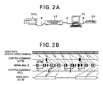
- FIGs.2A and 2B are diagrams exemplifying a transmission manner on a serial bus.
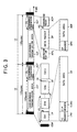
- FIG.3 is a diagram showing a configuration of an isochronous cycle.
- the serial bus standard is a standard for a serial bus to serially connect all information processors including current or future various electrical products to each other and mutually sending and receiving information between them.
- settings when the respective nodes are connected can be all automatically carried out. Moreover, a new node can be connected without turning off a power supply.
- a high speed transmission can be carried out in a range between 100 Mbps (bit per second) and 3.2 Gbps.
- various information can be transmitted by using real time transmission, two-way transmission and multiple-channel transmission.
- an information transmitting system S of FIG.1A for example, by setting a personal computer PC to be a route node (i.e., the node at the vertex on the topology in a form of tree, as mentioned above), various electrical products such as a CD (Compact Disc) player CP, an MD (Mini Disc) player MP, a digital video camera DVC, a printer PR, an LD (LASER Disc) player LP, a tuner T, a speaker SP, an amplifier AP, a television apparatus TV, a digital video tape recorder VT, a DVD player DV, a set top box SB for receiving a broadcast wave and the like can be respectively connected through a serial bus B so that the various electrical products can be supervised and controlled by the personal computer PC.
- a CD Compact Disc
- MD Minute Disc
- DVC digital video camera
- printer PR printer PR
- an LD (LASER Disc) player LP a tuner T
- speaker SP an amplifier AP
- the number of information processors (corresponding to the above-mentioned nodes) that can be included in one system (a system connected in a form of tree through the serial bus) is 63 at its maximum. Moreover, a maximum of 16 connections can be included between two nodes in the one system. In addition, it is inhibited on the serial bus standard to connect a plurality of nodes in a form of loop, as shown in FIG.1B, within the one system.
- the digital video camera DVC, the digital video tape recorder VT, the personal computer PC and the set top box SB are connected through the serial bus B to each other as respective nodes to accordingly carry out the information transmission. More concretely, it is supposed that video data from the digital video camera DVC, a predetermined control command from the digital video tape recorder VT, a control command to similarly control other units from the personal computer PC and image data (for example, MPEG data compressed in accordance with an MPEG (Moving Picture Expert Group) standard) included in the received broadcast wave from the set top box SB are sent out onto the serial bus B, respectively.
- image data for example, MPEG data compressed in accordance with an MPEG (Moving Picture Expert Group) standard
- the information from the respective nodes is transmitted while the information respectively occupies the serial bus B in time sharing, as shown in FIG.2B. Then, the various information is inserted into the isochronous cycle IC serving as a synchronous unit on the serial bus B having a length of 125 ⁇ sec and is then transmitted.
- the isochronous cycle IC is provided with: a cycle start packet CSP always inserted into a lead of the isochronous cycle IC in order to match standard times of all the nodes with each other; an isochronous transmission area ICT composed of isochronous packets IP corresponding to a plurality of channels and also constituted by a fact that temporally synchronous information are included in the respective isochronous packets IP; and an asynchronous transmission area ACT containing asynchronous information (for example, various control information, response information corresponding to the respective control information and the like).
- a sub-action gap SG which is a temporal gap indicative of an end of one isochronous transmission area ICT or an end of one asynchronous transmission area ACT, is inserted into a final tail of each isochronous transmission area ICT and a final tail of each asynchronous transmission area ACT.
- an isochronous gap IG which is a temporal gap indicative of an end of each packet is inserted between the respective isochronous packets IP and between the cycle start packet CSP and the lead isochronous packet IP.
- a length of the sub-action gap SG is set to be longer than that of the isochronous gap IG.
- One isochronous packet IP is composed of: an IP (Isochronous Packet) header IPH containing information indicative of a data amount within each isochronous packet IP, information indicative of a channel through which the information within each isochronous packet IP is transmitted and the like; a later-described CIP header CIPH; and a data area DF containing actual video information or audio information.
- IP IP
- Isochronous Packet IP (Isochronous Packet) header IPH containing information indicative of a data amount within each isochronous packet IP, information indicative of a channel through which the information within each isochronous packet IP is transmitted and the like
- CIP header CIPH information indicative of a channel through which the information within each isochronous packet IP is transmitted and the like
- a later-described CIP header CIPH a later-described CIP header CIPH
- a data area DF containing actual video information or audio information.
- a plurality of data blocks are included in the data
- the asynchronous transmission area ACT is composed of: an arbitration reset gap APG which is a temporal gap for each node to indicate that information from each node is sent out; a data packet DP containing data, such as control information to be asynchronously transmitted and the like; and an acknowledge packet ACP containing data to be used for a reply from a node of a transmission destination.
- an asynchronous gap AG which is a temporal gap indicative of an end of one data packet DP is inserted between the data packet DP and the acknowledge packet ACP.
- one data packet DP is provided with: an AP (Asynchronous Packet) header APH including information indicative of a destination of each data packet DP; and a data area ADF including information indicative of a transmission occupation period of a data packet DP occupying an asynchronous transmission area ACT, information indicative of an occupation channel or actual control information and the like.
- AP Asynchronous Packet
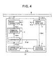
- FIG.4 is a block diagram showing the schematic configuration of an IRM node included in an information transmitting system of the first embodiment.
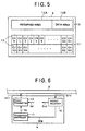
- FIG.5 is a diagram describing the content of a later-described resource register in the IRM node.
- FIG.6 is a block diagram showing the schematic configuration of another typical node included in the information transmitting system of the first embodiment.
- FIG.7 is a flowchart showing the processes in the IRM node of the first embodiment.
- FIG.8 is a flowchart showing the processes in another node of the first embodiment.
- FIG.9 is a diagram describing the transmission of information in the first embodiment, in time series.
- a CD player CP serving as the node has a configuration (mainly, a configuration for the information reproduction) as the CD player CP itself, in addition to a configuration described below.
- an IRM node NI serving as an indicating device in the first embodiment is provided with a packet transmitter 1, a transmission controller 2, a comparison register 3, a packet receiver 4 and a resource register 5 serving as a transmission state memory and a referring device memory.
- the resource register 5 is a register for storing a channel currently used on the serial bus B and a transmission occupation period currently being occupied, in a condition that they can be referred to on a list by other nodes.
- the transmission controller 2 is composed of a command generator 6 and a comparator 7 serving as a monitor.
- the packet receiver 4 receives reception data Srv from the serial bus B, in the normal information transmission, and then separates the above-mentioned video information and the like and a control information used to control the video information etc., from the reception data Srv, and further outputs it as input data Srd to a processor (not shown) (for example, a record processor for recording the video information inputted as the input data Srd if the IRM node NI is an MD player MP) of the IRM node NI (hereafter, the above-mentioned receiving process is referred to as a normal packet receiving process).
- a processor not shown
- the packet receiver 4 When a request of referring to a content (namely, the channel currently being used and the transmission occupation period currently being occupied) of the resource register 5 in order to start transmitting the information in the arbitration operation is transmitted from another node by using the asynchronous transmission area ACT, the packet receiver 4 receives this request, outputs the reference result to the packet transmitter 1, and again uses the asynchronous transmission area ACT to then transmit (send back) the reference result to the node transmitting the reference request.
- a request of referring to a content namely, the channel currently being used and the transmission occupation period currently being occupied
- the packet receiver 4 when a request to insure a channel and a transmission occupation period, respectively, to be used by it in the arbitration operation is transmitted from another node by using the asynchronous transmission area ACT, the packet receiver 4 outputs a write signal Swr to the resource register 5, in order to store into the resource register 5 the channel and the transmission occupation period which are desired to be insured.
- the resource register 5 outputs the memory and display content as a normal register signal Srg2 to the comparator 7.
- the resource register 5 outputs the memory and display content as a register signal Srg1 to the comparison register 3 for each preset predetermined time duration (for example, 1 second), and then rewrites a content of the comparison register 3 into a content similar to the memory and display content of the resource register 5 for each predetermined time.
- the write signal Swr is outputted by the packet receiver 4 in the arbitration operation, the resource register 5 updates the memory and display content, in accordance with its content.
- the control information indicating that a channel used by the node and a transmission occupation period occupied by the node are released (namely, the usage and the occupation are ended) is transmitted by using the asynchronous transmission area ACT, a fact that a new empty channel is generated and also the occupied transmission occupation period is decreased is transmitted as a write signal Swr to the resource register 5.
- the memory and display content of the resource register 5 is updated also in this case.
- the memory area of the resource register 5 is provided with an occupation period memory 10 indicative of a transmission occupation period currently being occupied, and a channel memory 11 for storing and displaying a channel currently being used.
- the occupation period memory 10 is composed of a reserved area 10A in which data is not stored at all as a reservation, and a data area 10B indicative of a remaining transmission occupation period that is not currently occupied.
- a maximum value among the values stored in the data area 10B is stored and displayed if the data is not sent or received on the serial bus B (namely, a remainder of the transmission occupation period is 100 ⁇ sec), as the memory and display manner of the data area 10B.
- the transmission occupation period is gradually occupied by the respective nodes.
- the stored value is reduced correspondingly to the newly occupied transmission occupation period. Accordingly, a remaining transmission occupation period is stored and displayed that can be occupied by a node which tries to start transmitting information from now.
- the channel memory 11 has 63 usage state memory areas 12 prepared for each channel allowed to be used on the serial bus standard.
- a value "0" is stored in a usage state memory area 12 corresponding to the channel being used.
- a value "1” is stored in a usage state memory area 12 corresponding to a non-used channel.
- the channel currently being used by any one of nodes is stored and displayed.
- the comparison register 3 re-writes its memory content in accordance with a register signal Ssg1 for each above-mentioned predetermined time, and always outputs the memory content as a register signal Srg3 to the comparator 7 (hereafter, this process of the normal information transmission process is referred to as a "comparison buffer process").
- the comparator 7 always compares the content of the register signal Srg2 from the resource register 5 with the content of the register signal Srg3 from the comparison register 3, in the normal information transmission. If a difference occurs between both the contents, the comparator 7 generates a comparison signal Scm indicative of the occurrence of the difference, and outputs it to the command generator 6.
- the register signal Srg2 is always outputted by the resource register 5, the register signal Srg1 is outputted only for each above-mentioned predetermined time.
- the register signal Srg3 is always outputted to the comparator 7.
- the generation of the comparison signal Scm is limited to the case when the resource register 5 is re-written (in other words, in a case of the occurrence of a channel to be newly used and the increase of the occupied transmission occupation period, or in a case of the occurrence of a new empty channel and the decrease of the occupied transmission occupation period).
- the command generator 6 generates a report command to report to the respective nodes the fact that the content of the resource register 5 is re-written (namely, the states of the usage channel and the transmission occupation period are changed), in accordance with the comparison signal Scm from the comparator 7, and then outputs it as a command signal Sco to the packet transmitter 1.
- the packet transmitter 1 inserts the command signal Sco into the asynchronous transmission area ACT, generates a transmission data Str, transmits it through the serial bus B to all other nodes, and then reports to the other nodes the change of the states of the transmission occupation period and the usage channel on the serial bus B.
- the packet transmitter 1 transmits the reference result of the resource register 5 to a node requesting the reference, by using the asynchronous transmission area ACT.
- the packet transmitter 1 performs a predetermined packet process etc., with respect to an output data Sd (for example, an output data Sd including the audio information reproduced by the MD player MP, if the IRM node NI is the MD player MP) which is generated by other elements (not shown) of the IRM node NI and is to be outputted by the IRM node NI, to thereby form the isochronous packets IP and further transmits it onto the serial bus B (hereafter, this transmitting process in the normal information transmission is referred to as a "normal packet transmission process").
- an output data Sd for example, an output data Sd including the audio information reproduced by the MD player MP, if the IRM node NI is the MD player MP
- a general node N serving as the information processing apparatus in the first embodiment is provided with a packet transmitter 15 serving as a transmitter, a transmission controller 17 serving as an insuring unit and a packet receiver 16.
- the packet receiver 16 carries out a normal packet reception process similarly to the packet receiver 4 shown in FIG.4.
- the packet receiver 16 receives the reference result through the serial bus B and the packet transmitter 1 in the IRM node NI, and then transmits the result to a processor (not shown), so as to control an operation of newly insuring the above-mentioned channel and transmission occupation period.
- the packet receiver 16 when receiving the command signal Sco indicative of the change of the states of the transmission occupation period and the usage channel on the serial bus B from the IRM node NI through the serial bus B, the packet receiver 16 generates a report signal Smg indicative of the changes, and further outputs it to the transmission controller 17.
- the transmission controller 17 carries out the arbitration operation in accordance with the control of the processor (not shown), and then generates a request signal Sc of requesting a reference of the resource register 5 in the IRM node NI, and further outputs it to the packet transmitter 15. Also, if a channel and a transmission occupation period which the node N desires can be used as the reference result, the transmission controller 17 transmits the usable situation to the IRM node NI, and then updates the content of the resource register 5 (namely, the channel and the transmission occupation period which the node N newly uses are stored in the resource register 5).
- the transmission controller 17 carries out a reference request operation to the IRM node NI one time. As a result, if it is understood that the channel and the transmission occupation period desired by the node N can not be used, the transmission controller 17 does not carry out a new reference request operation until receiving the command signal Sco indicative of the changes of the states of the usage channel and the transmission occupation period on the serial bus B from the IRM node NI.
- the packet transmitter 15 inserts into the asynchronous transmission area ACT the control signal of requesting the reference of the resource register 5, in the arbitration operation, and then generates the transmission data Str, and further transmits it through the serial bus B to the IRM node NI.
- the control signal of requesting the reference is never transmitted until the command signal Sco indicative of the change of the states of the usage channel and the transmission occupation period on the serial bus B is newly received, in accordance with a control signal Sc from the transmission controller 17.
- the packet transmitter 15 carries out the normal packet transmission process in the normal information transmission.
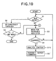
- Step S1 it is firstly monitored whether or not a bus reset occurs on the serial bus B (Step S1). If the bus reset occurs (Step S1 : YES), a topology is newly constructed (Step S6). Next, it is checked whether or not in the reconstructed topology, it becomes an IRM node by itself (Step S2). Then, if it does not become the IRM node (Step S2 : NO), the process ends as it is. On the other hand, if it becomes the IRM node (Step S2 : YES), the operational flow proceeds to the step S3 in order to continue the process as the IRM node.
- Step S3 a memory and display content is monitored.
- the comparator 7 always compares the content of the register signal Ssg2 from the resource register 5 with the content of the register signal Ssg3 from the comparison register 3, and accordingly monitors whether or not the difference occurs between both of the contents.
- Step S3 If the memory and display content of the resource register 5 is changed during the monitor (Step S3) (Step S4 : YES), a report command indicative of the change is transmitted as a command signal Sco to another node N (Step S5), and the operational flow again returns to the step S1, and the above-mentioned processes are repeated.
- Step S4 if the memory and display content of the resource register 5 is not changed in the judgment at the step S4 (Step S4 : NO), the operational flow returns back to the step S1 as it is without generating the report command. Then, the above-mentioned operations are repeated.
- the node N of the first embodiment firstly carries out the operations at the steps S1, S2 and S6 shown in FIG.7.
- the operational flow proceeds to the step S3 in FIG.7, in order to carry out the process as the IRM node shown in FIG.7.
- Step S7 if the bus reset does not occur (Step S1 : NO), or if it is not the IRM node (Step S1 : NO), it is then checked whether or not the information is to be transmitted from the node N (Step S7). If there is no information to be transmitted (Step S7 : NO), the operational flow returns back to the step S1 as it is, and the above-mentioned operations are repeated.
- Step S8 the content of the resource register 5 is referred as the arbitration operation, and also an operation for insuring a channel and a transmission occupation period which the node N desires for the information transmission is carried out (hereafter, the channel and the transmission occupation period on the serial bus B are typically referred to as a "resource") (Step S8).
- Step S9 it is judged whether or not the resource can be insured (namely, whether or not the desired channel is empty and further the desired transmission occupation period can be insured) (Step S9). If it can be insured (Step S9 : YES), the insured channel and transmission occupation period are used to transmit the information (Step S11). After that, the operational flow again returns to the step S1, and the above-mentioned processes are repeated.
- Step S9 if the desired resource cannot be insured in the judgment at the step S9 (Step S9 : NO), it is next checked whether or not a command signal Sco corresponding to the report command is received from the IRM node NI (Step S10). If it is not received (Step S10 : NO), the operational flow waits until the reception. If it is received (Step S10 : YES), the operational flow again returns to the step S8, and the operation of insuring the resource is again carried out. As a result, if the desired resource can be insured in accordance with the content of the re-written resource register 5 (Step S9 : YES), the transmission of the information is started as it is (Step S11). On the other hand, if it cannot be insured (Step S9 : NO), the operation of waiting for the arrival of the report command and again insuring the resource is repeated.
- the resource register 5 is re-written at a time T1 when the transmission of the information from the node N2 is ended. Accordingly, a report command indicative of the re-written fact is transmitted to all other nodes N. Then, in accordance with the memory and display content of the re-written resource register 5, a node N3 which can insure a new resource uses the desired channel and transmission occupation period from a time T2, and then starts transmitting the information.
- the operations of the IRM node NI and the node N of the first embodiment when the memory and display content of the resource register 5 in the IRM node NI is updated, the updated fact is reported through the serial bus B to another node N.
- the repetition of the useless or vain operation of insuring the resource can be avoided in the period while the memory content is not updated in each node N.
- the first embodiment may be designed as follows. That is, the IRM node NI stores a content of a resource requested by another node N. Then, if its desired resource is empty as an updated result of a content of the resource register 5, its fact is reported to the desired node N.
- the case is described in which when the memory and display content of the resource register 5 is updated, the report command is transmitted to all other nodes N.
- an ID number (identification number) of a node N which cannot insure a resource although it tries to refer to the memory and display content of the resource register 5, is stored in a part of a memory area in the resource register 5.
- a command signal Sco corresponding to the report command is transmitted only to the node N whose ID number is stored. Accordingly, the update of the memory and display content of the resource register 5 is reported only to the node N.
- FIG.10 is a flowchart showing the processes in an IRM node of the second embodiment
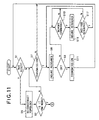
- FIG.11 is a flowchart showing the processes in another node of the second embodiment.
- the IRM node NI reports only the fact of the update in the memory and display content of its resource register 5 to another node N.
- the IRM node reports the content of the resource register 5 after the update, in addition to the fact of the update in the memory and display content of the resource register 5.
- the configurations of the IRM node and other typical nodes in the second embodiment are basically similar to those of the IRM node NI and the nodes N in the first embodiment. Thus, the explanations thereof are omitted. Only the operations as the second embodiment will be described below. Also, in the flowcharts in FIGs.10 and 11, the similar step numbers are given to the operations similar to the flowcharts shown in FIGs.7 and 8, and the explanations of the detailed portions are omitted.
- the operations at the steps S1 to S4 and S6 in the operations (refer to FIG.7) of the IRM node NI in the first embodiment are firstly executed in the IRM node NI in the second embodiment.
- Step S4 YES
- the comparator 7 serving as a detector next analyzes a non-occupied transmission occupation period and an empty channel after the update, in accordance with a content of the register signal Ssg2 (Step S15).
- the analysis result (namely, a number of the empty channel and a length of the non-occupied transmission occupation period) is added to the report command, and it is transmitted as the command signal Sco to another node N (Step S5'). Again, the operational flow returns back to the step S1, and the above-mentioned processes are repeated.
- Step S10 If the report command (which includes the actual number of the empty channel and the actual length of the non-occupied transmission occupation period after the update, in addition to the fact of update in the memory and display content of the resource register 5, as mentioned above) is received from the IRM node of the second embodiment (Step S10 : YES), the transmission controller 17 next analyzes the content of the report command to thereby check an empty resource (namely, the actual number of the empty channel and the actual length of the non-occupied transmission occupation period after the update) (Step S16). Moreover, it is judged whether or not a channel and a transmission occupation period desired by a node transmitting the information can be insured in the checked empty resource (Step S17). If the desired resource can be insured (Step S17 : YES), the operational flow proceeds to the step S8, and the resource is insured (Steps S8, S9 : YES). So, the information transmission is started (Step S11).
- Step S17 if it is judged in the judgment at the step S17 that the resource desired by the node is not empty in the empty resource included in the report command (Step S17 : NO), the operational flow returns back to the step S10 as it is, and waits until a next report command is transmitted from the IRM node in the second embodiment.
- the node which can not transmit the information, can quickly insure the empty resource to then start transmitting the information.
- the configuration similar to that of the first embodiment enables the fact of the change in the resource register 5 and the empty resource to be reported only to a node which cannot insure a resource although it refers to the resource register 5.
- a third embodiment which is another embodiment of the present invention executed in accordance with the serial bus standard will be described below with reference to FIGs.12 and 13.
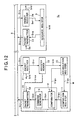
- FIG.12 is a block diagram showing the configuration of each node of the third embodiment
- FIG. 13 is a flowchart showing the processes in a management node of the third embodiment.
- the IRM node having the resource register 5 transmits the report command indicative of the fact of the update in the memory and display content of the resource register 5 and the like, to the other nodes.
- the management node which is a node different from the IRM node has the reporting function.
- FIG.12 the similar member numbers are given to the members similar to the respective members in the first or second embodiment. Thus, the explanations of the detailed portions are omitted.
- the configuration of the IRM node included in the information transmitting system S3 of the third embodiment is firstly described.
- an IRM node NIR of the third embodiment has the configuration similar to the IRM node typically defined on the serial bus standard, and it is actually provided with a resource register 5, a packet receiver 24 and a packet transmitter 23 similar to the case of the first or second embodiment.
- the packet receiver 24 carries out the above-mentioned normal packet reception process, in the normal information transmission.
- the packet receiver 24 When a request of referring to a content of the resource register 5 in order to start transmitting the information in the arbitration operation is transmitted from another node by using the asynchronous transmission area ACT, the packet receiver 24 receives this request, outputs the reference result as a register signal Srg to the packet transmitter 23, and then transmits (sends back) to the node transmitting the reference request. Also, when a request to insure a channel and a transmission occupation period, respectively, to be used by it in the arbitration operation is transmitted from another node by using the asynchronous transmission area ACT, the packet receiver 24 outputs a write signal Swr to the resource register 5, in order to store in the resource register 5 the channel and the transmission occupation period which are desired to be insured.
- the packet transmitter 23 carries out the above-mentioned normal packet transmission process in the normal information transmission.
- the packet transmitter 23 transmits the register signal Srg which is the reference result of the resource register 5, as the transmission data Str, to the node requesting the reference by using the asynchronous transmission area ACT, in the arbitration operation.
- the packet receiver 24 receives the read out request signal Srco. Accordingly, the packet transmitter 23 reads out the memory and display content of the resource register 5 as the register signal Srg, and then transmits it to the management node M as the transmission data Str.
- the configuration of the management node M included in the information transmitting system S3 of the third embodiment will be described below.
- the management node M of the third embodiment is provided with the transmission controller 2 and the comparison register 3 similar to those of the IRM node NI in the first or second embodiment, a packet transmitter 20, a packet receiver 21, a register reader 22 and an accumulation register 25.
- the packet receiver 21 carries out the above-mentioned normal packet reception process in the normal information transmission.
- the packet receiver 21 outputs the content as a content data Srr to the register reader 22.
- the register reader 22 generates the read out request signal Srco, for example, at a rate of one time for each 10 isochronous cycles IC, as described later, and then outputs it as the transmission data Str through the packet transmitter 20 to the IRM node NIR. Also, if the memory and display content of the resource register 5 is transmitted correspondingly to the outputted read out request signal Srco and then it is inputted as the content data Srr, the register reader 22 outputs it as a write signal Srm as it is to the accumulation register 25. Accordingly, the content of the resource register 5 is copied as it is to the accumulation register 25, for each 10 isochronous cycles IC.
- the accumulation register 25 outputs its memory and display content as a normal register signal Srg2 to the comparator 7.
- the accumulation register 25 outputs its memory and display content as a register signal Srg1 to the comparison register 3 for each preset predetermined time (for example, 1 second), and then re-writes a content of the comparison register 3 into a content similar to the memory and display content of the accumulation register 25 for each predetermined time.
- the IRM node NIR transmits a fact that a new empty channel is generated and also the occupied transmission occupation period is decreased, as a write signal Swr to the resource register 5. So, the memory and display content of the resource register 5 is updated, and the memory and display content of the accumulation register 25 is also updated at the substantially same time.
- the comparison register 3 carries out the comparison buffer process similar to that of the first embodiment.
- the comparator 7 always compares a content of the register signal Srg2 from the accumulation register 25 with the content of the register signal Srg3 from the comparison register 3, in the normal information transmission similarly to the case of the first embodiment. If a difference occurs between those two contents, the comparator 7 generates a comparison signal Scm indicative of the occurrence of the difference, and then outputs it to the command generator 6.
- the case when the difference occurs between the content of the register signal Srg2 and the content of the register signal Srg3 in the comparator 7 implies the case when the content of the accumulation register 25 (in other words, the resource register 5) is re-written in the predetermined time.
- the generation of the comparison signal Scm is limited to the case when the accumulation register 25 is re-written (in other words, in the case when a channel to be newly used is generated and the occupied transmission occupation period is increased, or in the case when a new empty channel is generated and the occupied transmission occupation period is decreased).
- the command generator 6 generates the report command to report to the respective nodes the fact that the content of the accumulation register 25 is re-written (namely, the states of the usage channel and the transmission occupation period are changed), in accordance with the comparison signal Scm from the comparator 7, similarly to the case of the first embodiment, and then outputs it as a command signal Sco to the packet transmitter 20.
- the packet transmitter 20 transmits it as the transmission data Str to the IRM node NIR. Also, when receiving the command signal Sco from the command generator 6, the packet transmitter 20 inserts the command signal Sco into the asynchronous transmission area ACT, generates the transmission data Str and transmits it through the serial bus B to all other nodes, so as to report to the other nodes the changes of the states of the transmission occupation period and the usage channel on the serial bus B.
- the packet transmitter 20 carries out the normal packet transmission process in the normal information transmission.
- Steps S3' and 54 the memory and display content of the resource register 5 is monitored (Steps S3' and 54).
- the register reader 22 firstly generates the read out request signal Srco, for example, for each 10 isochronous cycles IC to then output it to the IRM node NIR. Accordingly, the content of the resource register 5 is transferred from the IRM node NIR through the packet receiver 21 and the register reader 22 to the accumulation register 25.
- the comparator 7 carries out the process of always comparing the content of the register signal Ssg2 from the accumulation register 25 with the content of the register signal Ssg3 from the comparison register 3, so as to monitor whether or not the difference occurs between those two contents.
- Step S5 If the memory and display content of the accumulation register 25 (namely, the resource register 5) is changed during the monitor (Step S3') (Step S4 : YES), the report command indicative of the change is transmitted as the command signal Sco to another node N (Step S5), and the operational flow again returns to the step S1, and the above-mentioned processes are repeated.
- the configuration of the typical node other than the IRM node NIR and the management node M in the information transmitting system S3 of the third embodiment is perfectly similar to that of the node N in the first embodiment.
- the processes thereof are perfectly similar to those of the node N in the first embodiment except that the transmission source of the report command is the management node M.
- the explanations of the detailed portions are omitted.
- the node which monitors the resource register 5 and reports the update, is the node different from the IRM node NIR having the resource register 5, it can provide the effect similar to that of the first embodiment.
- the third embodiment may be designed as follows. That is, as the process until one of nodes becomes the management node M after the re-configuration of topology, for example, if a certain node has a function as the management node M, at a time of the re-configuration of the topology, when its ID number is transmitted onto the serial bus B, a flag indicative of its fact is added. After that, after the ID numbers are given to all the nodes, a node having the largest ID number among the nodes sending out the flag is defined as the management node M.
- the case is described in which when the memory and display content of the resource register 5 is updated, the report command is transmitted to all other nodes except the management node M.
- the following manner may be considered. That is, an ID number of a node, which cannot insure a resource although the node tries to refer to a memory and display content of a resource register 5, is stored in a part of the memory area of the resource register 5. Then, the ID number together with the memory and display content of the resource register 5 is read out to transfer them to the accumulation register 25. So, a command signal Sco corresponding to the report command is transmitted only to the node whose ID number is stored. Accordingly, the fact of the update in the memory and display content of the resource register 5 is reported only to the node.
- the following method may be considered other than the above-mentioned manner. For example, when a node tries to insure a resource for an IRM node NI, the IRM node NI makes the node insuring the resource recognize the ID number of the management node M. After this recognition, the information can be sent and received between the management node M and its node. Also, at a time of setting the management node M, if the ID number of the management node M is recognized by another node, it is enough that the node requesting the insurance of the resource directly reports its request to the management node M.
- a fourth embodiment which is another embodiment of the present invention executed in accordance with the serial bus standard will be described below with reference to FIG.14.
- FIG.14 is a flowchart showing the processes in an IRM node and a management node of the fourth embodiment.
- the management node M reports to the other nodes N only the fact of the update in the memory and display content of the resource register 5 in the IRM node NIR.
- the management node reports a content of the resource after the update, in addition to the fact of the update in the memory and display content of the resource register 5 in the IRM node.
- the configurations of the management node, the IRM node and the other general nodes in the fourth embodiment are basically similar to those of the management node M and the IRM node NIR in the third embodiment and the general nodes in the second embodiment. Thus, the explanations thereof are omitted. Only the operations as the fourth embodiment will be described below. Also, in the flowchart shown in FIG.14, the similar step numbers are given to the operations similar to those of the flowchart shown in FIG.10, and the explanations of the detailed portions are omitted.
- the operations at the steps S1 to S4 and S6 in the operations (refer to FIG.13) of the IRM node NIR in the third embodiment are firstly executed in the management node and the IRM node in the fourth embodiment.
- Step S4 If the memory and display content of the accumulation register 25 (namely, the resource register 5) is updated (Step S4 : YES), the transmission controller 2 next analyzes a non-occupied transmission occupation period and an empty channel after the update, in accordance with a content of the register signal Ssg2 (Step S15).
- Step S5' the operational flow returns to the step S1, and the abovementioned processes are repeated
- the processes of the general nodes other than the IRM node and the management node in the information transmitting system of the fourth embodiment are perfectly similar to those of the other nodes other than the IRM node in the second embodiment except that the transmission destination of the report command including the number of the empty channel and the length of the non-occupied transmission occupation period is the management node.
- the explanations of the detailed portions are omitted.
- the IRM node and the other nodes in the fourth embodiment if the memory and display content of the resource register 5 is updated, the detected empty resource together with the fact of the update is reported to the other nodes, in addition to the effect due to the operations of the management node M, the IRM node NI and the other nodes in the third embodiment.
- the node which cannot transmit the information, can quickly insure the empty resource to then start transmitting the information.
- the configuration similar to that of the third embodiment enables the fact of the change in the resource register 5 and the empty resource to be reported only to a node which cannot insure a resource although it refers to the resource register 5.
- the fourth embodiment may be designed such that the IRM node stores a content of a resource requested by another node, and if its desired resource becomes empty as an updated result of a content of the resource register 5, the IRM node reports the fact to the desiring node.
- a fifth embodiment which is another embodiment of the present invention executed in accordance with the serial bus standard will be described below with reference to FIGs.15 to 19.
- FIG.15 is a block diagram showing the schematic configuration of an IRM node included in an information transmitting system of the fifth embodiment.
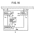
- FIG.16 is a block diagram showing the schematic configuration of another general node included in the information transmitting system of the fifth embodiment.
- FIG.17 is a flowchart showing the processes in the IRM node of the fifth embodiment.
- FIG.18 is a flowchart showing the processes in another node of the fifth embodiment.
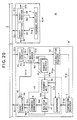
- FIG.19 is a diagram describing in time series the information transmission in the fifth embodiment
- the CD player CP serving as the node has the configuration of a music reproducing device as the CD player CP itself and the like, in addition to the following configuration.
- an IRM node NI' in the fifth embodiment is provided with a packet transmitter 30, a transmission controller 31, a comparison register 3 and a resource register 5 similar to those of the first embodiment, a packet receiver 32, and request registers 33 serving as transmitter memories in which the number of request registers corresponds to at least the number of other nodes connected to the IRM node NI' (its maximum number is ideally 63).
- the transmission controller 31 is composed of the command generator 6 and the comparator 7 similar to those of the first embodiment, a judgment unit 34 and a register writer 35 serving as a reservoir.
- the packet receiver 32 carries out the above-mentioned normal packet reception process in the normal information transmission.
- the packet receiver 32 receives the resource insurance request signal Sqr, and then stores it in a request register 33 corresponding to the node requesting the insurance of the resource.
- the content of the resource insurance request signal Sqr actually contains an ID number indicative of the node requesting the insurance of the resource and a content (actually, a channel and a transmission occupation period desired to be used) of the resource desired by the node.
- the packet receiver 32 When a request of referring to a content of the resource register 5 in order to start transmitting the information in the arbitration operation is transmitted from another node by using the asynchronous transmission area ACT, the packet receiver 32 receives this request, outputs the reference result to the packet transmitter 30, and again uses the asynchronous transmission area ACT to then transmit (send back) to the node transmitting the reference request. Also, when a request to insure a channel and a transmission occupation period, respectively, to be used by it in the arbitration operation is transmitted from another node by using the asynchronous transmission area ACT, the packet receiver 32 outputs a write signal Swr to the resource register 5, in order to store in the resource register 5 the channel and the transmission occupation period which are desired to be insured.
- the resource register 5 outputs its memory and display content as a normal register signal Srg2 to the comparator 7 and the judgment unit 34, similarly to the first embodiment.
- the resource register 5 outputs its memory and display content as a register signal Srg1 to the comparison register 3 for each preset predetermined time (for example, 1 second), and then re-writes a content of the comparison register 3 into a content similar to the memory and display content of the resource register 5 for each predetermined time.
- a later-described write signal Swr1 is transmitted by the register writer 35, the resource register 5 rewrites its memory and display content, in accordance with a content of the write signal Swr1.
- the resource register 5 updates the memory and display content in accordance with the content of the write signal Swr.
- the comparison register 3 carries out the comparison buffer process similar to that of the first embodiment.
- the comparator 7 always compares a content of the register signal Srg2 from the resource register 5 with that of the register signal Srg3 from the comparison register 3, in the normal information transmission. If a difference occurs between those two contents, the comparator 7 generates a comparison signal Scm indicative of the occurrence of the difference and then outputs it to the judgment unit 34.
- the generation of the comparison signal Scm from the comparator 7 is limited to the case when the resource register 5 is re-written, namely, the case of the occurrence of the channel to be newly used and the increase of the occupied transmission occupation period, or the case of the occurrence of the new empty channel and the decrease of the occupied transmission occupation period.
- the request register 33 stores the content of the signal Sqr separately for each node. Then, the request register 33 always outputs the content as a request register signal Srq to the judgment unit 34.
- the judgment unit 34 compares the content of the register signal Srg2 with the content of the request register signal Srq transmitted from any one of the request registers 33, at a timing when the comparator 7 generates the comparison signal Scm. If the content of the register signal Srg2 agrees with the content of the request register signal Srq transmitted from any one of the request registers 33 (namely, a resource of a content indicated by the request register signal Srq can be insured in the resource register 5), the judgment unit 34 generates a write control signal Sdd, and then outputs it to the register writer 35.
- the register writer 35 receiving the write control signal Sdd generates the write signal Swr1 in order to write the content of the resource to be insured, to the resource register 5, and outputs the write signal Swr1. to the resource register 5, so as to re-write the memory and display content of the resource register 5, and also generates an insurance signal Swc indicative of the insurance of the resource to then output it to the command generator 6.
- the command generator 6 generates, in accordance with the insurance signal Swc from the register writer 35, for a node (to the resource register 5 of which the writing operation is performed) requesting a resource newly insured by the register writer 35 among nodes transmitting the resource insurance request signal Sqr to the request register 33, a report command to report the insurance of the requested resource to the node, and then outputs it as a command signal Sco to the packet transmitter 30.
- the packet transmitter 30 inserts the command signal Sco into the asynchronous transmission area ACT to generate the transmission data Str, and also transmits it to the node requesting the requested resource through the serial bus B, and further reports to the node the completion of the insurance of the resource desired by the node.
- the packet transmitter 30 transmits the reference result of the resource register 5 to the node requesting the reference by using the asynchronous transmission area ACT, in the arbitration operation, and also carries out the normal packet transmission process in the normal information transmission.
- a general node N' in the fifth embodiment is provided with a packet transmitter 36, a transmission controller 37 serving as a referring device and a channel time reservoir, a packet receiver 16 similar to the case of the first embodiment and a resource insurance request unit 38 serving as a memory controller.
- the packet receiver 16 carries out the above-mentioned normal packet reception process in the normal information transmission, similarly to the case of the first embodiment.
- the packet receiver 16 When referring to the content of the resource register 5 in order to start transmitting the information in the arbitration operation, the packet receiver 16 receives the reference result through the serial bus B and the packet transmitter 30 in the IRM node NI', and then transmits the result to a processor (not shown), and further makes the processor carry out an operation of newly insuring the resource. Also, if the insurance of the desired resource is requested from the later-described resource insurance request unit 38 to the IRM node NI' since the resource cannot be insured, when a report command indicative of the insurance of the resource in response to the request is transmitted by the IRM node NI', the packet receiver 16 generates a report signal Smg indicative of the insurance of the resource, and then outputs it to the transmission controller 37.
- the transmission controller 37 when starting the transmission of the information from the node N', the transmission controller 37 carries out the arbitration operation in accordance with the control of the processor (not shown), and then generates a request signal Sc of requesting the reference of the resource register 5 in the IRM node NI', and further outputs to the packet transmitter 36. Also, if a resource desired by the node N' can be used as the reference result, the transmission controller 37 transmits the usable situation to the IRM node NI', so as to update the content of the resource register 5 (namely, the resource newly used by the node N is stored in the resource register 5 and displayed).
- the transmission controller 37 carries out a reference request operation to the IRM node NI' one time.
- the IRM node NI' instead of the node N', the IRM node NI' generates a resource insurance request signal Sqr of requesting the execution of the insurance of the resource desired by the node N', for the resource insurance request unit 38, and then generates a control signal Scrk to control the resource insurance request unit 38 so as to output the signal Sqr to the packet transmitter 36, and then outputs the control signal Scrk to the resource insurance request unit 38.
- the resource insurance request unit 38 generates the resource insurance request signal Sqr in accordance with the control signal Scrk, and then outputs it to the packet transmitter 36.
- the packet transmitter 36 carries out the above-mentioned normal packet transmission process in the normal information transmission.
- the packet transmitter 36 generates a transmission data Str by inserting into the asynchronous transmission area ACT a control signal of requesting the reference of the resource register 5 in the arbitration operation, by the operation of the transmission controller 37, and then transmits it through the serial bus B to the IRM node NI'. Also, if the resource cannot be insured, the packet transmitter 36 generates a transmission data Str including the resource insurance request signal Sqr, and then transmits it to the IRM node NI'.
- Step S2 If a power supply of the IRM node NI' is successively turned on (Step S2 : YES) or if the re-configuration of topology is completed (Step S6), it is next judged whether or not any one of nodes N' requests a resource insurance request signal Sqr of requesting an insurance of a resource desired by the node N' (Step S20). If it is not requested (Step S20 : NO), the operational flow returns back to the step S1 as it is, and the above-mentioned operations are repeated.
- Step S20 if the resource insurance request signal Sqr is transmitted (Step S20 : YES), the content of the desired resource included in the resource insurance request signal Sqr is stored into a request register 33 corresponding to the node N' transmitting the resource insurance request signal Sqr (Step S21).
- Step S3 and S4 it is monitored whether or not the resource register 5 is updated. If it is not updated (Step S4 : NO), the monitor is continued as it is. If it is updated (Step S4 : YES), the operation of insuring the resource corresponding to the resource insurance request signal Sqr stored at the step S21 is carried out (Step S22).
- the process at the step S22 is carried out as the target of each resource insurance process, in the order of starting from the request register 33 in which the resource insurance request signal Sqr is earlier stored, among the plurality of request registers 33.
- Step S23 it is checked whether or not the corresponding resource can be insured (Step S23). If it cannot be insured (actually, if the desired resource is not empty in the resource register 5 after the update) (Step S23 : NO), the operational flow again returns to the step S3, and the monitor of the resource register 5 is continued. On the other hand, if it can be insured (Step S23 : YES), a report command indicative of the insurance is transmitted to the node N' transmitting the resource insurance request signal Sqr corresponding to the insured resource (Step S24). After that, the content of the request register 33 is cleared which stores the resource insurance request signal Sqr corresponding to the insured resource (Step S25). Then, the operational flow returns back to the step S1, and the processes until now are repeated.
- Step S9 YES
- the insured resource is used to transmit the information (Step S11). After that, the operational flow again returns to the step S1, and the above-mentioned processes are repeated.
- Step S9 NO
- the resource insurance request signal Sqr is transmitted to the IRM node NI', which executes the insurance of the resource (Step S26).
- Step S27 it is checked whether or not the report command of reporting to the node N' the insurance of the resource requested through the resource insurance request signal Sqr is received, in accordance with a report signal Smg (Step S27). If it is not received (Step S27 : NO), the operational flow waits until the reception. If it is received (Step S27 : YES), the transmission of the information is started as it is (Step S11).
- the IRM node NI' instead of the node N' trying to transmit the information, the IRM node NI' insures the resource and reports to the node N'.
- the resource cannot be insured, it is possible to avoid the node N' from carrying out the operation of uselessly insuring the resource so that the resource can be effectively insured for the node N'.
- the information can be effectively transmitted as the entire information transmitting system.
- the IRM node NI' Only when the resource cannot be insured by the node N', the IRM node NI' carries out the insurance, instead of the node N'. Thus, the insurance can be effectively carried out while the load on the IRM node NI' is kept to a minimum.
- the judgment unit 34 determines the order of the insurance of the resource, in accordance with a preset priority for each node.
- a priority in an insurance of a resource to other nodes namely, a start of a transmission of the information
- a priority flag indicative of the set priority is simultaneously transmitted when the resource insurance request signal Sqr is transmitted to the IRM node NI'.
- a content of the priority flag is stored, for example, in the reserved area 10A (refer to FIG.5) of the resource register 5.
- the priority flag transmitted in conjunction with each resource insurance request signal Sqr is referred to. Accordingly, the request register 33 storing the resource insurance request signal Sqr having the higher priority is preferentially targeted by the resource insurance process.
- the insurance process as the target of the resource insurance process can be preferentially performed on a resource insurance request from a node closer to a route node (the personal PC in the case of FIG.1A).
- a route node the personal PC in the case of FIG.1A.
- each node adds a priority flag indicative of a priority corresponding to a position in the topology to the resource insurance request signal Sqr, and transmits it. It is stored in the resource register 5. Accordingly, the judgment unit 34 can recognize the priority.
- the priority in this case is set at a point when the topology is established. Thus, it is understood that the user does not set it artificially.
- the resources represented by the signal Sqr may be preferentially targeted by the resource insurance process, in such an order that the transmission occupation period is the shorter. Conversely, they may be preferentially targeted by the resource insurance process, in such an order that the transmission occupation period is the longer.
- a sixth embodiment which is another embodiment of the present invention executed in accordance with the serial bus standard will be described below with reference to FIGs.20 to 21.
- FIG.20 is a block diagram showing the configuration of each node included in an information transmitting system S6 of the sixth embodiment
- FIG.21 is a flowchart showing the processes in a management node of the sixth embodiment.
- the IRM node NI' having the resource register 5 insures the resource, instead of another node N'.
- a management node which is a node different from the IRM node executes the insurance of the resource.
- FIG.20 the similar member numbers are given to the members similar to the respective members in the fifth embodiment, and the explanations of the detailed portions are omitted.
- the configuration of the IRM node included in the information transmitting system of the sixth embodiment is firstly described.
- an IRM node NIR' of the sixth embodiment has the configuration similar to the IRM node typically defined on the serial bus standard, and it is actually provided with a resource register 5, a packet transmitter 45 and a packet receiver 46 similar to the case of the fifth embodiment.
- the packet receiver 46 carries out the above-mentioned normal packet reception process, in the normal information transmission.
- the packet receiver 46 When a request of referring to a content of the resource register 5 in order to start transmitting the information in the arbitration operation is transmitted from another node by using the asynchronous transmission area ACT, the packet receiver 46 receives this request, outputs the reference result as a register signal Srg to the packet transmitter 45, and then transmits (sends back) to the node transmitting the reference request. Also, when each insurance of a channel and a transmission occupation period to be used by it in the arbitration operation is transmitted from another node by using the asynchronous transmission area ACT, the packet receiver 46 outputs a write signal Swr to the resource register 5, in order to store into the resource register 5 the insured channel and transmission occupation period.
- the packet receiver 46 when a re-write signal Swr2 indicating that a memory and display content of the resource register 5 is rewritten is transmitted by a later-described management node M', the packet receiver 46 generates a write signal Swr so as to update the resource register 5, in accordance with a content indicated by the re-write signal Swr2, and then outputs it to the resource register 5.
- the packet transmitter 45 carries out the above-mentioned normal packet transmission process in the normal information transmission.
- the packet transmitter 45 transmits the register signal Srg which is the reference result of the resource register 5, as the transmission data Str, to the node requesting the reference by using the asynchronous transmission area ACT, in the arbitration operation.
- the packet receiver 46 receives the read out request signal Srco. Accordingly, the packet transmitter 45 reads out the memory and display content of the resource register 5 as a register signal Srg, and then transmits it to the management node M' as a transmission data Str.
- the management node M' in the sixth embodiment is provided with request registers 33 similar to the case of the IRM node NI' in the fifth embodiment, a comparison register 3, a transmission controller 47 containing a command generator 6, a comparator 7, a judgment unit 34 and a register writer 41, a packet receiver 44, a packet transmitter 40, an accumulation register 42 and a register reader 43.
- the packet receiver 44 carries out the above-mentioned normal packet reception process in the normal information transmission.
- the packet receiver 44 outputs the content as a content data Srr to the register reader 43.
- the packet receiver 44 receives the resource insurance request signal Sqr, and then stores it into a request register 33 corresponding to the node requesting the insurance of the resource, similarly to the packet receiver 32 in the fifth embodiment.
- the register reader 43 generates the read out request signal Srco, for example, at a rate of one time for each 10 isochronous cycles IC, and then outputs it as the transmission data Str through the packet transmitter 40 to the IRM node NIR'. Also, if the memory and display content of the resource register 5 is transmitted correspondingly to the outputted read out request signal Srco and then it is inputted as the content data Srr, the register reader 43 outputs it as it is as a write signal Srm to the accumulation register 42. Thus, the content of the resource register 5 is copied as it is to the accumulation register 42, for each 10 isochronous cycles IC.
- the accumulation register 42 outputs its memory and display content as a normal register signal Srg2 to the comparator 7 and the judgment unit 34.
- the accumulation register 42 outputs its memory and display content as a register signal Srg1 to the comparison register 3 for each preset predetermined time (for example, 1 second), and then re-writes a content of the comparison register 3 into a content similar to the memory and display content of the accumulation register 42 for each predetermined time.
- the IRM node NIR' transmits a fact that a new empty channel is generated and also the occupied transmission occupation period is decreased, as a write signal Swr to the resource register 5. Accordingly, the memory and display content of the resource register 5 is updated, and the memory and display content of the accumulation register 42 is also updated at the substantially same time.
- the comparison register 3 carries out the comparison buffer process similar to that of the first embodiment.
- the comparator 7 always compares a content of the register signal Srg2 from the accumulation register 42 with that of the register signal Srg3 from the comparison register 3, in the normal information transmission similarly to the case of the fifth embodiment. If a difference occurs between those two contents, the comparator 7 generates a comparison signal Scm indicative of the occurrence of the difference, and then outputs it to the judgment unit 34.
- the generation of the comparison signal Scm is limited to the case when the accumulation register 42 is re-written.
- the request register 33 stores the content of the signal Sqr separately for each node. Then, the request register 33 always outputs the content as a request register signal Srq to the judgment unit 34.
- the judgment unit 34 compares the content of the register signal Srg2 with the contents of the request register signals Srq transmitted from the respective request registers 33, at a timing when the comparator 7 generates the comparison signal Scm. If the content of the register signal Srg2 agrees with the content of any one of the request register signals Srq, the judgment unit 34 generates a write control signal Sdd, and then outputs it to the register writer 41.
- the register writer 41 receiving the write control signal Sdd generates the re-write signal Swr2 so as to write the content of the resource to be insured, to the resource register 5 in the IRM node NIR', and outputs the re-write signal Swr2 through the packet transmitter 40 to the IRM node NI', and re-writes the memory and display content of the resource register 5, and then generates an insurance signal Swc indicative of the insurance of the resource to output it to the command generator 6.
- the command generator 6 in accordance with the insurance signal Swc from the register writer 41, the command generator 6 generates, for a node requesting a resource newly insured by the register writer 41 among nodes transmitting the resource insurance request signals Sqr to the request registers 33, a report command to report the insurance of the requested resource to the node, and then outputs it as a command signal Sco to the packet transmitter 40.
- the packet transmitter 40 inserts the command signal Sco into the asynchronous transmission area ACT to thereby generate the transmission data Str, and also transmits it to the node requesting the requested resource through the serial bus B, and further reports to the node the completion of the insurance of the resource desired by the node.
- the packet transmitter 40 carries out the normal packet transmission process in the normal information transmission.
- Steps S3' and S4 the memory and display content of the resource register 5 is monitored. Actually, the processes at the steps S3' and S4 are executed similarly to the operations at the steps S3' and S4 in the third embodiment shown in FIG.13.
- Step S4 YES
- the operations at the steps S22 to S25 in the fifth embodiment are executed. Then, the operational flow again returns to the step S1, and the above-mentioned processes are repeated.
- the configuration of the typical node other than the IRM node NIR' and the management node M' in the information transmitting system of the sixth embodiment is perfectly similar to that of the node N' in the fifth embodiment.
- the processes thereof are perfectly similar to those of the node N' in the fifth embodiment except that the transmission destination of the resource insurance request signal Sqr is the management node M and also the transmission source of the report command is the management node M'.
- the explanations of the detailed portions are omitted.
- the operation of the IRM node NIR' and the management node M' in the sixth embodiment even if the node which monitors the resource register 5 and reports when the update is performed is the node different from the different from the IRM node NIR having the resource register 5, the effect similar to that of the fifth embodiment can be achieved.
- the following method may be considered. For example, when a node tries to insure a resource for an IRM node NIR', the IRM node NIR' makes the node insuring the resource recognize an ID number of the management node M'. After this recognition, the information can be sent and received between the management node M' and its node. Also, at a time of setting the management node M', if the ID number of the management node M' is recognized by another node, it is enough that the node requesting the insurance of the resource directly reports its request to the management node M'.
Landscapes
- Engineering & Computer Science (AREA)
- Signal Processing (AREA)
- Computer Networks & Wireless Communication (AREA)
- Multimedia (AREA)
- Small-Scale Networks (AREA)
- Information Transfer Systems (AREA)
- Time-Division Multiplex Systems (AREA)
Applications Claiming Priority (2)
| Application Number | Priority Date | Filing Date | Title |
|---|---|---|---|
| JP37441398 | 1998-12-28 | ||
| JP10374413A JP2000196624A (ja) | 1998-12-28 | 1998-12-28 | 伝送管理装置、情報処理装置及び情報伝送システム |
Publications (2)
| Publication Number | Publication Date |
|---|---|
| EP1017236A2 true EP1017236A2 (de) | 2000-07-05 |
| EP1017236A3 EP1017236A3 (de) | 2000-11-22 |
Family
ID=18503806
Family Applications (1)
| Application Number | Title | Priority Date | Filing Date |
|---|---|---|---|
| EP99125960A Withdrawn EP1017236A3 (de) | 1998-12-28 | 1999-12-27 | Vorrichtung zur Übertragungsverwaltung, Vorrichtung zur Informationsverarbeitung, und System zur Informationsübertragung |
Country Status (3)
| Country | Link |
|---|---|
| US (2) | US6594239B1 (de) |
| EP (1) | EP1017236A3 (de) |
| JP (1) | JP2000196624A (de) |
Families Citing this family (10)
| Publication number | Priority date | Publication date | Assignee | Title |
|---|---|---|---|---|
| JP4881500B2 (ja) * | 1999-12-09 | 2012-02-22 | ソニー株式会社 | 情報処理装置および情報処理方法、コンテンツ提供装置およびコンテンツ提供方法、再生装置および再生方法、並びに記録媒体 |
| JP3454217B2 (ja) * | 1999-12-28 | 2003-10-06 | 日本電気株式会社 | 通信経路制御方法、機器制御装置、及びブリッジ |
| US20020073169A1 (en) * | 2000-04-12 | 2002-06-13 | Yoshiyuki Takaku | Information processing apparatus, information processing system and method thereof |
| ES2272541T3 (es) * | 2000-08-23 | 2007-05-01 | Koninklijke Philips Electronics N.V. | Sistema y dispositivo de comunicaciones. |
| DE10113261C2 (de) * | 2001-03-16 | 2003-07-10 | Siemens Ag | Synchrones, getaktetes Kommunikationssystem mit dezentralen Ein-/Ausgabe-Baugruppen und Verfahren zur Einbindung dezentraler Ein-/Ausgabe-Baugruppen in ein solches System |
| FI115272B (fi) * | 2001-12-14 | 2005-03-31 | Abb Oy | Menetelmä ja laite tiedon välittämisen tietoliikennejärjestelmässä |
| JP4286791B2 (ja) * | 2002-11-18 | 2009-07-01 | シャープ株式会社 | ネットワーク中継装置、ネットワーク中継方法、ネットワーク中継プログラム、および、ネットワーク中継プログラムを記録した記録媒体 |
| JP2004186769A (ja) * | 2002-11-29 | 2004-07-02 | Toshiba Corp | 通信システム、通信制御方法、及び通信制御端末 |
| JP2005012260A (ja) * | 2003-06-16 | 2005-01-13 | Matsushita Electric Ind Co Ltd | データ伝送の制御方法 |
| US9785593B2 (en) * | 2014-09-17 | 2017-10-10 | Htc Corporation | Portable device with data transmission between main system and subsystem and control method therefor |
Family Cites Families (13)
| Publication number | Priority date | Publication date | Assignee | Title |
|---|---|---|---|---|
| JPH08126072A (ja) * | 1994-10-20 | 1996-05-17 | Pioneer Electron Corp | 車載用データ通信システム及びその通信方法 |
| JP3348330B2 (ja) | 1995-04-21 | 2002-11-20 | ソニー株式会社 | 通信制御方法 |
| US5815678A (en) | 1995-07-14 | 1998-09-29 | Adaptec, Inc. | Method and apparatus for implementing an application programming interface for a communications bus |
| US6233637B1 (en) * | 1996-03-07 | 2001-05-15 | Sony Corporation | Isochronous data pipe for managing and manipulating a high-speed stream of isochronous data flowing between an application and a bus structure |
| JPH1040211A (ja) * | 1996-04-30 | 1998-02-13 | Texas Instr Inc <Ti> | パケット化されたデータ通信インタフェース機器内での直接メモリアクセス優先順位を割り当てるための方法ならびにdmaチャンネル回路 |
| US6332159B1 (en) * | 1996-12-04 | 2001-12-18 | Canon Kabushiki Kaisha | Data communication system, apparatus and controlling method thereof |
| JPH10229410A (ja) * | 1997-02-14 | 1998-08-25 | Canon Inc | データ処理装置、電子機器および通信システム |
| DE69837356T2 (de) | 1997-02-14 | 2007-11-29 | Canon K.K. | Vorrichtung, System und Verfahren zur Datenübertragung und Vorrichtung zur Bildverarbeitung |
| US6473816B1 (en) * | 1997-12-04 | 2002-10-29 | Canon Kabushiki Kaisha | Apparatus and method for determining bus use right |
| JPH11168473A (ja) * | 1997-12-04 | 1999-06-22 | Matsushita Electric Ind Co Ltd | シリアルバス管理装置 |
| US6160796A (en) * | 1998-01-06 | 2000-12-12 | Sony Corporation Of Japan | Method and system for updating device identification and status information after a local bus reset within a home audio/video network |
| JP3277874B2 (ja) * | 1998-01-29 | 2002-04-22 | 日本電気株式会社 | Ieee1394ブリッジ |
| US6167471A (en) * | 1998-10-14 | 2000-12-26 | Sony Corporation | Method of and apparatus for dispatching a processing element to a program location based on channel number of received data |
-
1998
- 1998-12-28 JP JP10374413A patent/JP2000196624A/ja active Pending
-
1999
- 1999-12-27 US US09/472,665 patent/US6594239B1/en not_active Expired - Fee Related
- 1999-12-27 EP EP99125960A patent/EP1017236A3/de not_active Withdrawn
-
2003
- 2003-06-02 US US10/452,536 patent/US6894986B2/en not_active Expired - Fee Related
Also Published As
| Publication number | Publication date |
|---|---|
| JP2000196624A (ja) | 2000-07-14 |
| EP1017236A3 (de) | 2000-11-22 |
| US20030206555A1 (en) | 2003-11-06 |
| US6894986B2 (en) | 2005-05-17 |
| US6594239B1 (en) | 2003-07-15 |
Similar Documents
| Publication | Publication Date | Title |
|---|---|---|
| JP4155413B2 (ja) | アプリケーションとバス間の非同期データ転送を自動的に管理する非同期データパイプ | |
| US6993646B2 (en) | Automatically configuring storage array including plurality of media storage devices for storing and providing data within a network of devices | |
| US20020196197A1 (en) | Control system for controlling an imaging device and a personal computer wherein imaging device control conditions may be freely set between the imaging device and the personal computer | |
| CN1082296C (zh) | 控制通信的方法和其电子设备 | |
| CN1190834A (zh) | 通信方法和使用这种方法的电子装置 | |
| US20030179719A1 (en) | Method and apparatus for transmitting packets at a transfer rate that depends on a response from a destination | |
| US6594239B1 (en) | Transmission managing apparatus, information processing apparatus and information transmitting system | |
| JP2000059755A (ja) | データサーバシステム、データ受信装置およびデータ送信装置 | |
| US6272114B1 (en) | Data processing apparatus/method and electronic apparatus with such apparatus/method | |
| US6381655B1 (en) | System for transmitting information about an electronic unit stored in a storage means having a hierarchical data structure to one of a plurality of electronic units | |
| US6505264B1 (en) | Information transmitting apparatus and method, information receiving apparatus and method, and information transmitting/receiving apparatus and method | |
| JPH10341247A (ja) | データ送信装置、データ受信装置、データ伝送システム及びデータ伝送方法 | |
| KR100311707B1 (ko) | 데이타 통신 시스템, 데이타 통신 방법, 데이타 통신 장치 및 디지탈 인터페이스 | |
| US6925500B1 (en) | Control device, control method and medium | |
| KR20020011927A (ko) | 통신 제어 방법, 통신 시스템 및 통신 장치 | |
| US20010024445A1 (en) | Communication system, communication device and communication method | |
| US6584534B1 (en) | Combined isochronous and asynchronous communication apparatus, method and interface | |
| US7124292B2 (en) | Automatically configuring storage array including a plurality of media storage devices for storing and providing data within a network of devices | |
| JP4046846B2 (ja) | データ通信システム及びデータ通信装置 | |
| EP1178631A2 (de) | Kommunikationssteuerverfahren, Kommunikationssystem und Kommunikationsgerät | |
| JPWO2000069121A1 (ja) | 情報処理方法、情報処理システム及び情報処理装置 | |
| JP3676618B2 (ja) | パケット転送装置、及びデータ記録媒体 | |
| JP3678245B2 (ja) | マネージャ機器及び通信制御方法 | |
| JP3678241B2 (ja) | 電子機器及び通信制御方法 | |
| JP3678244B2 (ja) | 電子機器及び通信制御方法 |
Legal Events
| Date | Code | Title | Description |
|---|---|---|---|
| PUAI | Public reference made under article 153(3) epc to a published international application that has entered the european phase |
Free format text: ORIGINAL CODE: 0009012 |
|
| AK | Designated contracting states |
Kind code of ref document: A2 Designated state(s): DE FR GB |
|
| AX | Request for extension of the european patent |
Free format text: AL;LT;LV;MK;RO;SI |
|
| PUAL | Search report despatched |
Free format text: ORIGINAL CODE: 0009013 |
|
| AK | Designated contracting states |
Kind code of ref document: A3 Designated state(s): AT BE CH CY DE DK ES FI FR GB GR IE IT LI LU MC NL PT SE |
|
| AX | Request for extension of the european patent |
Free format text: AL;LT;LV;MK;RO;SI |
|
| RIC1 | Information provided on ipc code assigned before grant |
Free format text: 7H 04N 7/24 A, 7G 06F 13/00 B, 7H 04L 29/06 B |
|
| 17P | Request for examination filed |
Effective date: 20010112 |
|
| AKX | Designation fees paid |
Free format text: DE FR GB |
|
| 17Q | First examination report despatched |
Effective date: 20080526 |
|
| STAA | Information on the status of an ep patent application or granted ep patent |
Free format text: STATUS: THE APPLICATION IS DEEMED TO BE WITHDRAWN |
|
| 18D | Application deemed to be withdrawn |
Effective date: 20081007 |