EP1017322B1 - Support de lancettes intradermiques - Google Patents
Support de lancettes intradermiques Download PDFInfo
- Publication number
- EP1017322B1 EP1017322B1 EP98925114A EP98925114A EP1017322B1 EP 1017322 B1 EP1017322 B1 EP 1017322B1 EP 98925114 A EP98925114 A EP 98925114A EP 98925114 A EP98925114 A EP 98925114A EP 1017322 B1 EP1017322 B1 EP 1017322B1
- Authority
- EP
- European Patent Office
- Prior art keywords
- plunger
- blade
- casing
- spring
- skin
- Prior art date
- Legal status (The legal status is an assumption and is not a legal conclusion. Google has not performed a legal analysis and makes no representation as to the accuracy of the status listed.)
- Expired - Lifetime
Links
- 238000006073 displacement reaction Methods 0.000 claims description 2
- 230000037431 insertion Effects 0.000 claims description 2
- 238000003780 insertion Methods 0.000 claims description 2
- 210000003811 finger Anatomy 0.000 description 4
- 239000008280 blood Substances 0.000 description 2
- 210000004369 blood Anatomy 0.000 description 2
- 239000000463 material Substances 0.000 description 2
- 229920003023 plastic Polymers 0.000 description 2
- 239000004033 plastic Substances 0.000 description 2
- 239000007787 solid Substances 0.000 description 2
- 210000003813 thumb Anatomy 0.000 description 2
- 0 CC(C1)(C1CC1)C1C=*C* Chemical compound CC(C1)(C1CC1)C1C=*C* 0.000 description 1
- 241000700605 Viruses Species 0.000 description 1
- 238000010276 construction Methods 0.000 description 1
- 201000010099 disease Diseases 0.000 description 1
- 208000037265 diseases, disorders, signs and symptoms Diseases 0.000 description 1
- 230000000694 effects Effects 0.000 description 1
- 208000015181 infectious disease Diseases 0.000 description 1
- 230000000149 penetrating effect Effects 0.000 description 1
- 238000009877 rendering Methods 0.000 description 1
Images



Classifications
-
- A—HUMAN NECESSITIES
- A61—MEDICAL OR VETERINARY SCIENCE; HYGIENE
- A61B—DIAGNOSIS; SURGERY; IDENTIFICATION
- A61B5/00—Measuring for diagnostic purposes; Identification of persons
- A61B5/15—Devices for taking samples of blood
- A61B5/151—Devices specially adapted for taking samples of capillary blood, e.g. by lancets, needles or blades
- A61B5/15142—Devices intended for single use, i.e. disposable
- A61B5/15144—Devices intended for single use, i.e. disposable comprising driving means, e.g. a spring, for retracting the piercing unit into the housing
-
- A—HUMAN NECESSITIES
- A61—MEDICAL OR VETERINARY SCIENCE; HYGIENE
- A61B—DIAGNOSIS; SURGERY; IDENTIFICATION
- A61B5/00—Measuring for diagnostic purposes; Identification of persons
- A61B5/15—Devices for taking samples of blood
- A61B5/150007—Details
- A61B5/150015—Source of blood
- A61B5/150022—Source of blood for capillary blood or interstitial fluid
-
- A—HUMAN NECESSITIES
- A61—MEDICAL OR VETERINARY SCIENCE; HYGIENE
- A61B—DIAGNOSIS; SURGERY; IDENTIFICATION
- A61B5/00—Measuring for diagnostic purposes; Identification of persons
- A61B5/15—Devices for taking samples of blood
- A61B5/150007—Details
- A61B5/150206—Construction or design features not otherwise provided for; manufacturing or production; packages; sterilisation of piercing element, piercing device or sampling device
- A61B5/150259—Improved gripping, e.g. with high friction pattern or projections on the housing surface or an ergonometric shape
-
- A—HUMAN NECESSITIES
- A61—MEDICAL OR VETERINARY SCIENCE; HYGIENE
- A61B—DIAGNOSIS; SURGERY; IDENTIFICATION
- A61B5/00—Measuring for diagnostic purposes; Identification of persons
- A61B5/15—Devices for taking samples of blood
- A61B5/150007—Details
- A61B5/150374—Details of piercing elements or protective means for preventing accidental injuries by such piercing elements
- A61B5/150381—Design of piercing elements
- A61B5/150412—Pointed piercing elements, e.g. needles, lancets for piercing the skin
- A61B5/150427—Specific tip design, e.g. for improved penetration characteristics
-
- A—HUMAN NECESSITIES
- A61—MEDICAL OR VETERINARY SCIENCE; HYGIENE
- A61B—DIAGNOSIS; SURGERY; IDENTIFICATION
- A61B5/00—Measuring for diagnostic purposes; Identification of persons
- A61B5/15—Devices for taking samples of blood
- A61B5/150007—Details
- A61B5/150374—Details of piercing elements or protective means for preventing accidental injuries by such piercing elements
- A61B5/150381—Design of piercing elements
- A61B5/150412—Pointed piercing elements, e.g. needles, lancets for piercing the skin
- A61B5/150435—Specific design of proximal end
-
- A—HUMAN NECESSITIES
- A61—MEDICAL OR VETERINARY SCIENCE; HYGIENE
- A61B—DIAGNOSIS; SURGERY; IDENTIFICATION
- A61B5/00—Measuring for diagnostic purposes; Identification of persons
- A61B5/15—Devices for taking samples of blood
- A61B5/150007—Details
- A61B5/150374—Details of piercing elements or protective means for preventing accidental injuries by such piercing elements
- A61B5/150381—Design of piercing elements
- A61B5/150442—Blade-like piercing elements, e.g. blades, cutters, knives, for cutting the skin
- A61B5/150458—Specific blade design, e.g. for improved cutting and penetration characteristics
-
- A—HUMAN NECESSITIES
- A61—MEDICAL OR VETERINARY SCIENCE; HYGIENE
- A61B—DIAGNOSIS; SURGERY; IDENTIFICATION
- A61B5/00—Measuring for diagnostic purposes; Identification of persons
- A61B5/15—Devices for taking samples of blood
- A61B5/150007—Details
- A61B5/150374—Details of piercing elements or protective means for preventing accidental injuries by such piercing elements
- A61B5/150534—Design of protective means for piercing elements for preventing accidental needle sticks, e.g. shields, caps, protectors, axially extensible sleeves, pivotable protective sleeves
- A61B5/150633—Protective sleeves which are axially extensible, e.g. sleeves connected to, or integrated in, the piercing or driving device; pivotable protective sleeves
- A61B5/150641—Protective sleeves which are axially extensible, e.g. sleeves connected to, or integrated in, the piercing or driving device; pivotable protective sleeves comprising means to impede repositioning of protection sleeve from covering to uncovering position
- A61B5/150648—Protective sleeves which are axially extensible, e.g. sleeves connected to, or integrated in, the piercing or driving device; pivotable protective sleeves comprising means to impede repositioning of protection sleeve from covering to uncovering position fully automatically triggered, i.e. the triggering of the protective sleeve does not require a deliberate action by the user such as terminating the contact with the patient's skin
-
- A—HUMAN NECESSITIES
- A61—MEDICAL OR VETERINARY SCIENCE; HYGIENE
- A61B—DIAGNOSIS; SURGERY; IDENTIFICATION
- A61B5/00—Measuring for diagnostic purposes; Identification of persons
- A61B5/15—Devices for taking samples of blood
- A61B5/150007—Details
- A61B5/150374—Details of piercing elements or protective means for preventing accidental injuries by such piercing elements
- A61B5/150534—Design of protective means for piercing elements for preventing accidental needle sticks, e.g. shields, caps, protectors, axially extensible sleeves, pivotable protective sleeves
- A61B5/150694—Procedure for removing protection means at the time of piercing
- A61B5/150717—Procedure for removing protection means at the time of piercing manually removed
-
- A—HUMAN NECESSITIES
- A61—MEDICAL OR VETERINARY SCIENCE; HYGIENE
- A61B—DIAGNOSIS; SURGERY; IDENTIFICATION
- A61B5/00—Measuring for diagnostic purposes; Identification of persons
- A61B5/15—Devices for taking samples of blood
- A61B5/151—Devices specially adapted for taking samples of capillary blood, e.g. by lancets, needles or blades
- A61B5/15101—Details
- A61B5/15103—Piercing procedure
- A61B5/15107—Piercing being assisted by a triggering mechanism
- A61B5/15111—Semi-automatically triggered, e.g. at the end of the cocking procedure, for instance by biasing the main drive spring or when reaching sufficient contact pressure, the piercing device is automatically triggered without any deliberate action by the user
-
- A—HUMAN NECESSITIES
- A61—MEDICAL OR VETERINARY SCIENCE; HYGIENE
- A61B—DIAGNOSIS; SURGERY; IDENTIFICATION
- A61B5/00—Measuring for diagnostic purposes; Identification of persons
- A61B5/15—Devices for taking samples of blood
- A61B5/151—Devices specially adapted for taking samples of capillary blood, e.g. by lancets, needles or blades
- A61B5/15101—Details
- A61B5/15115—Driving means for propelling the piercing element to pierce the skin, e.g. comprising mechanisms based on shape memory alloys, magnetism, solenoids, piezoelectric effect, biased elements, resilient elements, vacuum or compressed fluids
- A61B5/15117—Driving means for propelling the piercing element to pierce the skin, e.g. comprising mechanisms based on shape memory alloys, magnetism, solenoids, piezoelectric effect, biased elements, resilient elements, vacuum or compressed fluids comprising biased elements, resilient elements or a spring, e.g. a helical spring, leaf spring, or elastic strap
-
- A—HUMAN NECESSITIES
- A61—MEDICAL OR VETERINARY SCIENCE; HYGIENE
- A61B—DIAGNOSIS; SURGERY; IDENTIFICATION
- A61B5/00—Measuring for diagnostic purposes; Identification of persons
- A61B5/15—Devices for taking samples of blood
- A61B5/151—Devices specially adapted for taking samples of capillary blood, e.g. by lancets, needles or blades
- A61B5/15101—Details
- A61B5/15126—Means for controlling the lancing movement, e.g. 2D- or 3D-shaped elements, tooth-shaped elements or sliding guides
- A61B5/15128—Means for controlling the lancing movement, e.g. 2D- or 3D-shaped elements, tooth-shaped elements or sliding guides comprising 2D- or 3D-shaped elements, e.g. cams, curved guide rails or threads
-
- A—HUMAN NECESSITIES
- A61—MEDICAL OR VETERINARY SCIENCE; HYGIENE
- A61B—DIAGNOSIS; SURGERY; IDENTIFICATION
- A61B5/00—Measuring for diagnostic purposes; Identification of persons
- A61B5/15—Devices for taking samples of blood
- A61B5/150007—Details
- A61B5/150763—Details with identification means
- A61B5/150786—Optical identification systems, e.g. bar codes, colour codes
Definitions
- THIS INVENTION relates to skin prickers.
- EP-A-0293092 discloses a skin pricker having a casing and a plunger which are displaceable with respect to one another when the plunger is placed against the skin to be pricked and the casing is pushed towards the plunger to trigger operation of the skin pricker, the skin pricker further including a lancet blade, a spring acting on the lancet blade for urging the lancet blade in a skin pricking forward stroke and then withdrawing it to an inoperative position, said blade being displaced with the plunger and with respect to the casing during relative movement between the plunger and casing, energy being stored in the spring during such relative movement, and the blade thereafter being disconnected from the plunger thereby to permit the spring to exert itself and urge said blade in said forward stroke relative to the casing and the plunger.
- the invention provides a skin pricker having a casing and a plunger which are displaceable with respect to one another when the plunger is placed against the skin to be pricked and the casing is pushed towards the plunger to trigger operation of the skin pricker, the skin pricker further including a lancet blade, a spring acting on the lancet blade for urging the lancet blade in a skin pricking forward stroke, said blade being displaced with the plunger and with respect to the casing during relative movement between the plunger and casing, energy being stored in the spring during such relative movement, and the blade thereafter being disconnected from the plunger thereby to permit the spring to exert itself and urge said blade in said forward stroke relative to the casing and the plunger, characterized by means interconnecting the plunger and blade so that the blade and plunger move as a unit during an initial part of said relative movement and by stop means which become effective at the end of said initial part of said relative movement between the plunger and casing to prevent further movement of said blade with the plunger, there being
- said spring is of sinusoidal form and includes a series of waves, the spring including stops for limiting closing-up of the waves, said stops constituting said stop means.
- it can include a series of thinner curved portions joined by thicker generally straight portions.
- said blade can have two points for pricking the skin at two adjacent locations.
- said blade is secured to an element which includes at least one shear pin which initially is contacted by a surface of the plunger so that the plunger and element form a unit and the casing moves relatively to this unit, said pin being sheared of by said surface when said stop means becomes effective to limit further movement of said element with respect to the casing thereby to permit the spring to exert itself and urge said blade and element in said forward stroke.
- said blade is secured to an element which includes at least one cam which is initially contacted by a surface of the plunger, and is displaced by that surface, so that the plunger and element form a unit and the casing moves relatively to this unit, said surface being on a plate which is resiliently flexible, said cam temporarily camming said plate to a deflected position upon said stop means becoming effective to limit further movement of said element with respect to the casing so that said cam disengages from said surface and the element and blade are free from restraint by the plunger thereby to permit the spring to exert itself and urge said blade and element in said forward stroke.
- Said plate desirably has an elongate slot in it which said cam enters and can thereafter move along after camming said plate to its deflected position and disengaging from said surface.
- said plunger fits telescopically into an open end of said casing, there being interengaging elongate grooves and latches for preventing said plunger being removed from the casing after insertion whilst permitting relative telescopic movement.
- said blade is secured to an element which includes at least one cam which is initially contacted by a surface of the plunger, and is displaced by that surface, so that the plunger and element form a unit and the casing moves relatively to this unit, said surface being on a plate which is resiliently flexible, said cam temporarily camming said plate to a deflected position upon said stop means becoming effective to limit further movement of said element with respect to the casing so that said cam disengages from said surface and the element and blade are free from restraint by the plunger thereby to permit the spring to exert itself and urge said blade and element in said forward stroke, said plunger including a head and a parallel spaced pair of said plates protruding from a rear face thereof, said head having an opening in it through which said blade projects during said forward stroke.
- the skin pricker casing part 10 shown in Figure 1 comprises a main wall 12 which is of elongate rectangular shape.
- Flanges 14 and 16 protrude from the edges of the wall 12.
- Each flange 14 and 16 is formed with a narrow groove 18 near the rear end of the casing part and a wider groove 20 near the front end thereof.
- Two casing parts 10, which have been designated 10.1 and 10.2 in Figure 2 are ultrasonically welded together with the upper and lower flanges 14, 16 abutting to form a casing.
- the flanges are designated 14.1, 14.2, 16.1, 16.2 and the main walls are designated 12.1 and 12.2.
- the plunger shown in Figure 3 is designated 22. It comprises two main walls 24 with upper and lower flanges 26 and 28 spanning between the upper and lower horizontal edges thereof thereby to form a box-like construction. Latches 30 extend upwardly and downwardly from the flanges 26 and 28 and there is a notch 32 in the rear edge of each main wall 24.
- a front closure structure 34 is provided, this structure comprising a head 36 with an opening 38 in it. The opening 38 narrows in the forward direction, that is, to the left as viewed in Figure 3.
- the plunger 22 is thus open at its rear end (the right hand end as viewed in Figure 3) and has an internal cavity 40. The opening 38 leads into the cavity 40.
- the spring and lancet blade assembly of Figure 4 is designated 42 and comprises an element 44 which carries a lancet blade 46.
- the element 44 is of synthetic plastics material and a rear end portion of the blade 46 is moulded into it.
- Co-axial shear pins 48 protrude from opposed main faces 50 of the element 44 and the element 44 is moulded integrally with a sinusoidal spring 52.
- a plug 54 At the end of the spring 52 remote from the element 44 there is a plug 54, the spring 52 and plug 54 also being moulded integrally with one another.
- the plug 54 has two protrusions 56 and a dished rear surface 58 against which thumb pressure can be exerted by the user of the skin pricker.
- a stop 60 protrudes rearwardly from the element 44 and a stop 62 protrudes forwardly from the plug 54.
- the stops are on the "axis" of the spring 52.
- Further stops 64 protrude forwardly and rearwardly at each point where the "waves" of the spring cross the axis, that is, cross the line joining the centres of the stops 60 and 62.
- the stops 60, 62 and 64 limit the degree to which the spring 52 can be compressed.
- the lancet blade 46 and element 44 are entered in the cavity 40 of the plunger 22 through the open rear end thereof.
- the shear pins 48 enter the notches 32.
- the tip of the blade 46 is at the point designated 46.1 in Figure 5, that is, it is well clear of the opening 38.
- the structure just described is then placed on the casing part 10.1.
- the protrusions 56 enter the narrow grooves 18 and this locates the rear end of the structure with respect to the casing part 10.
- the surface 58 is accessible from externally of the casing.
- the protrusions or latches 30 enter the elongate grooves 20.
- the other casing part 10.2 is placed over the casing part 10.1 and the flanges 14.1, 14.2, 16.1, 16.2 welded or glued together.
- the skin pricker is now as shown in Figure 5, one end of the skin pricker casing being closed by the plug 54 and the plunger 22 protruding from the other end of the casing.
- the external transverse dimensions of the plunger 22 are such that it fits in the cavity of the casing which cavity is best seen in Figure 2.
- the casing In use of the skin pricker, the casing is gripped and the head 36 of the plunger 22 pressed against the part of the body that is to be penetrated by pressure exerted on the plug 54. This pressure causes the plunger 22 to slide into the casing (see Figure 6), the protrusions 30 moving along the grooves 20 and the gaps between the stops 60, 62, 64 closing up. These gaps are eliminated before the protrusions 30 reach the rear ends of the grooves 20. The stops now form a solid rod between the element 44 and the plug 54. There is still a slight gap (designated 66 in Figure 6) between the rear face of the head 36 of the plunger 22 and the front end of the skin pricker casing.
- the spring 52 and element 44 are now incapable of further movement and further movement of the plunger 22 has to be accommodated by relative movement between the plunger 22 and the element 44.
- the pins 48 are thus sheared off by pressure exerted on them by the surfaces bounding the notches 32.
- the spring 52 is extended at this time beyond the position it adopts when completely relaxed. As soon as the element 44 hits the inside face of the head 36, the spring recoils and returns to its relaxed condition withdrawing the blade 46 to the position shown in Figure 8.
- the blade 46 is entirely within the plunger 22 and inaccessible from outside the skin pricker. Regardless of where the protrusions 30 are in the grooves 20, the blade 46 cannot protrude through the opening 38. Furthermore, it is impossible for the skin pricker to be used again because, in the absence of the pins 48, the spring 42 cannot be re-compressed which is a necessary pre-requisite to urging the blade 46 forward in a penetrating stroke. Thus neither other patients nor staff are in danger of infection from a skin pricker which has already been used.
- the casing 100 illustrated is of hollow elongate form with a generally rectangular cavity therein (see particularly Figure 12).
- the casing 100 is open at both ends and has, close to one end, a pair of external grooves 102 which traverse the major faces of the casing.
- the major faces also have therein two depressions 104 which are ribbed and facilitate gripping of the casing 100.
- At one end of the casing there are two internal recesses 106, the recesses being in the inner faces of the two major walls of the casing 100.
- Two grooves 108 run substantially the full length of the casing. More specifically, each groove 108 extends from one end of the casing 100 and terminates at a position close to the other end of the casing 100.
- a spring and lancet blade assembly is shown in Figures 14 and 15 and is generally designated 110.
- the assembly 110 comprises an element 112 which has a double pointed lancet blade 114 partially embedded therein and protruding from one end thereof.
- the element 112 is in the form of an elongate block, there being a cam 116 standing proud of each of the major faces of the block.
- the element 112 is moulded integrally with a generally sinusoidal spring 118.
- the spring 118 is itself moulded integrally with a plug 120.
- the plug 120 has a protrusion 122 on each face thereof and a dished rear surface 124 against which thumb pressure can be exerted by the user of the skin pricker.
- a stop 126 protrudes rearwardly from the element 112 and a stop 128 protrudes forwardly from the plug 120. Further stops 130 protrude forwardly from the spring at each point where the "waves" of the spring cross the main axis. The stops 126, 128 and 130 limit the degree to which the spring 118 can be compressed.
- the plunger illustrated is generally designated 132 and comprises a head 134 with an opening 136 in it. Protruding from the head 134 are two spaced, thin plates 138 each of which has an elongate slot 140 therein. A notch 142 is formed in the end of each plate 138 remote from the head 134.
- Fingers 144 also protrude from the head 134, the fingers 144 substantially closing the upper and lower ends of the gap between the plates 138.
- a triangular latch 146 protrudes from the outer face of each finger 144.
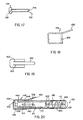
- the cap shown in Figures 18 and 19 is designated 148, is of generally hollow configuration and is open on one side only.
- a tear-off strip 150 is attached to the remainder of the cap 148 along weakened lines 152.
- the entrance to the hollow interior of the cap 150 is bounded, on each of two of the opposed faces thereof, by a protruding rib 154.
- the plunger 132 is inserted through the left hand end of the casing 100 as viewed in Figure 20.
- the latches 146 are cammed inwardly by the end portion of the casing which is not provided with grooves 108. Immediately the latches 146 reach the grooves 108 they snap outwardly and enter the grooves. Engagement between those surfaces of the latches 146 which are normal to the fingers 144 and the end faces of the grooves 108 prevents the plunger 132 thereafter being removed from the casing 100.
- the assembly 110 is inserted through the right hand end of the casing 100 (as viewed in Figure 20) and pushed in until the protrusions 122 enter the recesses 106. This locks the plug 120 in place and closes-off one end of the casing 100.
- the element 112 passes between the plates 138.
- the cams 116 of the element 112 enter the notches 142.
- the lancet blade 114 is well spaced from the opening 136 in the head 134 and there is no danger that anyone handling the skin pricker will be cut.
- the cap 148 is then pushed over the left hand end of the casing 100 until the ribs 154 enter the grooves 102.
- the cap 148 cannot thereafter be removed from the casing 100 without pulling on the strip 150 to tear the cap 148 along the weakened lines 152 and release the ribs 154 from the grooves 102.
- the plunger 132 protrudes from the casing 100 and lies within the cap 148.
- the plunger 132 is accessible. It is placed on the part of the body that is to be punctured.
- the casing 100 gripped by means of the depressions 104, is pushed towards said body part. This causes the plunger 132 to move into the casing 100, the protrusions 116, and hence the element 112, being pushed back by the plunger 132 and the latches 146 sliding along the grooves 108.
- the spring 118 compresses until the stops 126, 128 and 130 form a solid "rod" between the element 112 and the plug 120. Once the spring 118 is fully compressed, the element 112 can no longer move with the plunger 132. Further pressure on the plunger 132 causes relative movement between the plunger and the element 112.
- the cams 116 cam the plates 138 apart and the cams 116, upon further relative movement between the plunger 132 and the element 112 occurring, enter the slots 140.
- the compressed spring 118 is then able to force the element 112 to the left as it is no longer restrained by the plunger 132.
- the blade 114 emerges through the opening 136 and penetrates the body part.
- the spring 118 at this time has moved beyond its relaxed condition. It then recoils to its relaxed condition withdrawing the blade 114 to a position within the plunger 132.
- the plunger 132 cannot be pushed any further into the casing 100 which movement might expose the blade 114. Furthermore, even if the plunger 132 is withdrawn from the casing 100 to the full extent allowed by the latches 146, and then pushed back into the casing, the spring 118 is not compressed because there is no longer any connection between the plunger 132 and the element 112, the cams 116 simply sliding along the slots 140.
- the spring 156 shown in Figures 21, 22 and 23 is intended for use in the skin prickers of Figures 1 to 8 and of Figures 9 to 20 and replaces the springs 52 and 118. It is moulded using synthetic plastics material and comprises a series of thicker portions 158 and a series of thinner portions 160, the thicker portions 158 and thinner portions 160 alternating with one another.
- the crests and troughs of the "waves" of the spring 156 are constituted by the thinner portions 160.
- the crests and troughs of the spring are constituted by the thinner portions 160, and it is the thinner portions 160 that bend when the spring 156 is compressed or tensioned, the force needed to compress or tension the spring is less than would be needed had the entire spring been of the thickness of the portions 158.
- the provision of the thinner portions 160 ensures that relatively low forces applied to the skin prickers are sufficient to compress the spring. If the thinner portions 160 had the same cross-section as the thicker portions 158, an unacceptably large force would be required to compress the spring 156.
Landscapes
- Health & Medical Sciences (AREA)
- Life Sciences & Earth Sciences (AREA)
- Engineering & Computer Science (AREA)
- Heart & Thoracic Surgery (AREA)
- Molecular Biology (AREA)
- Pathology (AREA)
- Physics & Mathematics (AREA)
- Biomedical Technology (AREA)
- Hematology (AREA)
- Medical Informatics (AREA)
- Biophysics (AREA)
- Surgery (AREA)
- Animal Behavior & Ethology (AREA)
- General Health & Medical Sciences (AREA)
- Public Health (AREA)
- Veterinary Medicine (AREA)
- Dermatology (AREA)
- Manufacturing & Machinery (AREA)
- Measurement Of The Respiration, Hearing Ability, Form, And Blood Characteristics Of Living Organisms (AREA)
Claims (9)
- Support de lancettes intradermiques présentant un corps (10 ; 100) et un piston (22 ; 132) qui peuvent être déplacés l'un par rapport à l'autre lorsque le piston est placé contre la peau pour être piqué et que le corps est poussé en direction du piston pour déclencher le fonctionnement du support de lancettes intradermiques, ledit support comprenant en outre une lame formant lancette (46 ; 114), un ressort (52 ; 118 ; 156) agissant sur la lame formant lancette pour la pousser dans une course de travail piquant la peau, ladite lame étant déplacée avec le piston et par rapport au corps pendant le mouvement relatif entre le piston et le corps, de l'énergie étant stockée dans le ressort pendant ledit mouvement relatif, et la lame étant par la suite mise hors de prise avec le piston pour ainsi permettre au ressort d'exercer un effort sur lui-même et de pousser ladite lame dans ladite course de travail par rapport au corps et au piston, caractérisé par des moyens (32, 48, 116, 138) d'interconnexion du piston et de la lame de façon à ce que la lame et le piston se meuvent comme une unité pendant une partie initiale dudit mouvement relatif et par des moyens d'arrêt (62, 64 ; 126, 128, 130) qui deviennent effectifs à l'extrémité de ladite partie initiale dudit mouvement relatif entre le piston et le corps pour empêcher un autre mouvement de ladite lame avec le piston, une ouverture existant entre une face dudit corps et une face dudit piston à l'extrémité de ladite partie initiale de façon à ce qu'un mouvement soit possible entre ledit corps et ledit piston après que le déplacement de ladite lame avec le piston a été effectué, lesdites faces étant transversales à la direction du mouvement relatif du piston et du corps, lesdits moyens d'interconnexion du piston et de la lame étant mis hors de prise pendant ledit autre mouvement relatif pour libérer la lame pour ladite course de travail.
- Support de lancettes intradermiques selon la revendication 1, dans lequel ledit ressort (52 ; 118 ; 156) est de forme sinusoïdale et comprend une série d'ondulations, le ressort comprenant des butées (62, 64 ; 126 ; 128 ; 130) pour limiter la fermeture des ondulations, lesdites butées constituant lesdits moyens d'arrêt.
- Support de lancettes intradermiques selon la revendication 2, dans lequel ledit ressort comprend une série de parties incurvées (160) assemblées par des parties (158) plus épaisses généralement droites.
- Support de lancettes intradermiques selon la revendication 1, 2 ou 3, dans lequel ladite lame (114) présente deux points pour piquer la peau à deux endroits adjacents.
- Support de lancettes intradermiques selon les revendications 1, 2, 3 ou 4, dans lequel ladite lame est fixée à un élément (44) qui comprend au moins une goupille de cisaillement (48) qui est mise en contact par une surface (32) du piston de façon à ce que le piston et l'élément forment une unité et que le corps se déplace par rapport à cette unité, ladite goupille étant cisaillée par ladite surface lorsque lesdits moyens d'arrêt (62, 64) deviennent efficaces pour limiter un autre mouvement dudit élément par rapport au corps pour ainsi permettre au ressort (52 ; 156) d'exercer un effort sur lui-même et de pousser ladite lame et ledit élément dans ladite course de travail.
- Support de lancettes intradermiques selon les revendications 1, 2, 3 ou 4, dans lequel ladite lame est fixée à un élément (112) qui comprend au moins une came (116) qui est initialement mise en contact par une surface (142) du piston (132), et est déplacée par ladite surface, de façon à ce que le piston et l'élément forment une unité et que le corps se déplace par rapport à cette unité, ladite surface étant sur une plaque (138) qui est flexible de manière élastique, ladite came entraínant temporairement ladite plaque à une position déviée sur lesdits moyens d'arrêt (126, 128, 130) devenant efficaces pour limiter un autre mouvement dudit élément par rapport au corps de façon à ce que ladite came se mette hors de prise avec ladite surface et que l'élément et la lame ne soient pas sollicités par le piston pour ainsi permettre au ressort d'exercer un effort sur lui-même et de pousser ladite lame et ledit élément dans ladite course de travail.
- Support de lancettes intradermiques selon les revendications 1, 2, 3 ou 4, dans lequel ladite lame (114) est fixée à un élément (112) qui comprend au moins une came (116) qui est initialement mise en contact par une surface (142) du piston (132), et est déplacée par ladite surface, de façon à ce que le piston et l'élément forment une unité et que le corps se déplace par rapport à cette unité, ladite surface étant sur une plaque (138) qui est flexible de manière élastique, ladite came entraínant temporairement ladite plaque à une position déviée sur lesdits moyens d'arrêt (126, 128, 130) devenant efficaces pour limiter un autre mouvement dudit élément par rapport au corps de façon à ce que ladite came se mette hors de prise avec ladite surface et que l'élément et la lame ne soient pas sollicités par le piston pour ainsi permettre au ressort d'exercer un effort sur lui-même et de pousser ladite lame et ledit élément dans ladite course de travail, ladite plaque présentant une fente allongée (140) dans laquelle ladite came entre et peut par la suite circuler après avoir entraíné ladite plaque à sa position déviée et s'être mise hors de prise avec ladite surface.
- Support de lancettes intradermiques selon les revendications 1, 2, 3 ou 4, dans lequel ladite lame (114) est fixée à un élément (112) qui comprend au moins une came (116) qui est initialement mise en contact par une surface (142) du piston (132), et est déplacée par ladite surface, de façon à ce que le piston et l'élément forment une unité et que le corps se déplace par rapport à cette unité, ladite surface étant sur une plaque (138) qui est flexible de manière élastique, ladite came entraínant temporairement ladite plaque à une position déviée sur lesdits moyens d'arrêt (126, 128, 130) devenant efficaces pour limiter un autre mouvement dudit élément par rapport au corps de façon à ce que ladite came se mette hors de prise avec ladite surface et que l'élément et la lame ne soient pas sollicités par le piston pour ainsi permettre au ressort d'exercer un effort sur lui-même et de pousser ladite lame et ledit élément dans ladite course de travail, ledit piston comprenant une tête (134) et une paire desdites plaques (138) espacées de manière parallèle faisant saillie à partir de la face arrière de celle-ci, ladite tête présentant une ouverture (136) à travers laquelle ladite lame fait saillie pendant ladite course de travail.
- Support de lancettes intradermiques selon l'une quelconque des revendications précédentes, dans lequel ledit piston (22 ; 132) se loge de manière télescopique dans une extrémité ouverte dudit corps (10 ; 100), des rainures allongées (20 ; 108) étant en prise les unes avec les autres et des cliquets (30 ; 140) existant pour empêcher ledit piston d'être enlevé du corps après insertion alors qu'il permet un mouvement télescopique relatif.
Applications Claiming Priority (5)
| Application Number | Priority Date | Filing Date | Title |
|---|---|---|---|
| ZA9704842 | 1997-06-02 | ||
| ZA974842 | 1997-06-02 | ||
| ZA9800980 | 1998-02-06 | ||
| ZA98980 | 1998-02-06 | ||
| PCT/US1998/011163 WO1998055034A1 (fr) | 1997-06-02 | 1998-06-02 | Support de lancettes intradermiques |
Publications (3)
| Publication Number | Publication Date |
|---|---|
| EP1017322A1 EP1017322A1 (fr) | 2000-07-12 |
| EP1017322A4 EP1017322A4 (fr) | 2001-04-04 |
| EP1017322B1 true EP1017322B1 (fr) | 2004-03-17 |
Family
ID=27143907
Family Applications (1)
| Application Number | Title | Priority Date | Filing Date |
|---|---|---|---|
| EP98925114A Expired - Lifetime EP1017322B1 (fr) | 1997-06-02 | 1998-06-02 | Support de lancettes intradermiques |
Country Status (7)
| Country | Link |
|---|---|
| US (1) | US6299626B1 (fr) |
| EP (1) | EP1017322B1 (fr) |
| AU (1) | AU7713598A (fr) |
| DE (1) | DE69822487T2 (fr) |
| ES (1) | ES2221987T3 (fr) |
| WO (1) | WO1998055034A1 (fr) |
| ZA (1) | ZA986020B (fr) |
Families Citing this family (31)
| Publication number | Priority date | Publication date | Assignee | Title |
|---|---|---|---|---|
| US8814896B2 (en) | 1999-11-02 | 2014-08-26 | Stat Medical Devices, Inc. | Single use lancet assembly |
| US20050070945A1 (en) | 1999-11-02 | 2005-03-31 | Steven Schraga | Single use lancet assembly |
| AU2002310432A1 (en) | 2001-06-13 | 2003-06-23 | Steven Schraga | Single use lancet device |
| PL193168B1 (pl) * | 2001-08-13 | 2007-01-31 | Htl Strefa Sp Z Oo | Lancet |
| US8048097B2 (en) | 2001-08-14 | 2011-11-01 | Steven Schraga | Single use lancet assembly |
| US20040039407A1 (en) * | 2002-04-29 | 2004-02-26 | Steven Schraga | Lancet device |
| US8715309B2 (en) | 2002-04-29 | 2014-05-06 | Steven Schraga | Lancet device |
| US8052628B1 (en) | 2002-10-08 | 2011-11-08 | Vitalwear, Inc. | Spinal column brace for a contrast therapy system |
| US8425579B1 (en) | 2002-10-08 | 2013-04-23 | Vitalwear, Inc. | Therapeutic knee brace for a contrast therapy system |
| US7694693B1 (en) | 2002-10-08 | 2010-04-13 | Vitalwear, Inc. | Mixing valve for a contrast therapy system |
| US7658205B1 (en) | 2002-12-19 | 2010-02-09 | Vitalwear, Inc. | Systems for a fluid circuit coupler |
| US7191798B2 (en) * | 2002-12-19 | 2007-03-20 | Vital Wear, Inc. | Fluid circuit connector system |
| GB0320283D0 (en) * | 2003-08-29 | 2003-10-01 | Owen Mumford Ltd | Improvements relating to lancets |
| US9380975B2 (en) * | 2004-05-07 | 2016-07-05 | Becton, Dickinson And Company | Contact activated lancet device |
| US9066688B2 (en) * | 2004-05-07 | 2015-06-30 | Becton, Dickinson And Company | Contact activated lancet device |
| PL1755456T3 (pl) * | 2004-05-07 | 2010-03-31 | Becton Dickinson Co | Urządzenie lancetowe uruchamiane przez przyłożenie |
| US7766845B2 (en) * | 2004-06-21 | 2010-08-03 | Roche Diagnostics Operations, Inc. | Disposable lancet and lancing cap combination for increased hygiene |
| US7727166B2 (en) * | 2004-07-26 | 2010-06-01 | Nova Biomedical Corporation | Lancet, lancet assembly and lancet-sensor combination |
| DE102004058164B4 (de) * | 2004-12-02 | 2009-04-16 | Roche Diagnostics Gmbh | Stechvorrichtung zur Entnahme von Blut und Verfahren zur Herstellung dafür |
| GB0427891D0 (en) * | 2004-12-21 | 2005-01-19 | Owen Mumford Ltd | Skin pricking apparatus |
| US7935063B2 (en) * | 2005-03-02 | 2011-05-03 | Roche Diagnostics Operations, Inc. | System and method for breaking a sterility seal to engage a lancet |
| AU2006235418B2 (en) | 2005-04-07 | 2011-11-10 | Becton, Dickinson And Company | Lancet device |
| EP2337497A2 (fr) | 2008-07-29 | 2011-06-29 | Facet Technologies, LLC | Lancettes dotées de caractéristiques d'accouplement améliorées et de capsules garantissant la stérilité |
| JP5336601B2 (ja) * | 2009-10-07 | 2013-11-06 | 株式会社旭ポリスライダー | ランセット穿刺デバイス |
| US8647357B2 (en) | 2011-02-05 | 2014-02-11 | Birch Narrows Development Llc | Lancet device with flexible cover |
| US9237866B2 (en) | 2013-04-29 | 2016-01-19 | Birch Narrows Development, LLC | Blood glucose management |
| GB2521150B (en) * | 2013-12-10 | 2016-04-27 | Owen Mumford Ltd | Skin pricking lancets |
| ES2864412T3 (es) | 2014-07-18 | 2021-10-13 | Becton Dickinson Co | Dispositivo de lanceta con retirada de la primera gota |
| USD806246S1 (en) | 2016-02-25 | 2017-12-26 | Steven Schraga | Lancet cover |
| US11801068B2 (en) | 2019-06-25 | 2023-10-31 | William Ma | Sheathed cutting device |
| GB2633608A (en) * | 2023-09-15 | 2025-03-19 | Owen Mumford Ltd | Single use lancing device |
Family Cites Families (12)
| Publication number | Priority date | Publication date | Assignee | Title |
|---|---|---|---|---|
| US514375A (en) | 1894-02-06 | miller | ||
| US4616649A (en) * | 1984-09-20 | 1986-10-14 | Becton, Dickinson And Company | Lancet |
| US4991827A (en) * | 1986-11-10 | 1991-02-12 | Tayco Developments, Inc. | Springs formed of rope pressure-saturated or impregnated with binder |
| GB8710470D0 (en) * | 1987-05-01 | 1987-06-03 | Mumford Ltd Owen | Blood sampling devices |
| US5147375A (en) * | 1991-05-31 | 1992-09-15 | Ann Sullivan | Safety finger prick instrument |
| DE69229180T2 (de) | 1991-11-12 | 1999-10-14 | Urs. A. Ramel | Lanzetteneinrichtung |
| GB9207120D0 (en) | 1992-04-01 | 1992-05-13 | Owen Mumford Ltd | Improvements relating to blood sampling devices |
| US5395387A (en) | 1993-02-26 | 1995-03-07 | Becton Dickinson And Company | Lancet blade designed for reduced pain |
| US5439473A (en) | 1993-12-13 | 1995-08-08 | Modulohm A/S | Safety lancet |
| GB9422260D0 (en) | 1994-11-04 | 1994-12-21 | Owen Mumford Ltd | Improvements relating to skin prickers |
| US6113620A (en) * | 1996-07-12 | 2000-09-05 | Il Yang Pharm. Co., Ltd. | Magnetic needle for acupuncture |
| US6062548A (en) * | 1996-09-11 | 2000-05-16 | Exedy Corporation | Vibration attenuating spring and damper mechanism using the same spring |
-
1998
- 1998-06-02 WO PCT/US1998/011163 patent/WO1998055034A1/fr not_active Ceased
- 1998-06-02 AU AU77135/98A patent/AU7713598A/en not_active Abandoned
- 1998-06-02 EP EP98925114A patent/EP1017322B1/fr not_active Expired - Lifetime
- 1998-06-02 US US09/445,138 patent/US6299626B1/en not_active Expired - Fee Related
- 1998-06-02 DE DE69822487T patent/DE69822487T2/de not_active Expired - Fee Related
- 1998-06-02 ES ES98925114T patent/ES2221987T3/es not_active Expired - Lifetime
- 1998-07-08 ZA ZA986020A patent/ZA986020B/xx unknown
Also Published As
| Publication number | Publication date |
|---|---|
| AU7713598A (en) | 1998-12-21 |
| EP1017322A4 (fr) | 2001-04-04 |
| WO1998055034A1 (fr) | 1998-12-10 |
| EP1017322A1 (fr) | 2000-07-12 |
| DE69822487D1 (de) | 2004-04-22 |
| ZA986020B (en) | 1999-01-27 |
| ES2221987T3 (es) | 2005-01-16 |
| US6299626B1 (en) | 2001-10-09 |
| DE69822487T2 (de) | 2005-03-24 |
Similar Documents
| Publication | Publication Date | Title |
|---|---|---|
| EP1017322B1 (fr) | Support de lancettes intradermiques | |
| US5487748A (en) | Blood sampling device | |
| EP0433050B1 (fr) | Améliorations pour instruments de prélèvement du sang | |
| US7955347B2 (en) | Low cost safety lancet | |
| EP2459067B1 (fr) | Dispositif de lancette avec rétraction de lame | |
| JP5596823B2 (ja) | ランセット穿刺デバイス | |
| JP2788249B2 (ja) | 廃棄式プリッカ | |
| CN1846612B (zh) | 一次性使用的刺血针设备 | |
| US5921969A (en) | Apparatus for shielding a butterfly needle | |
| JP4642082B2 (ja) | ランセットアッセンブリおよび穿刺デバイス | |
| US20030229316A1 (en) | Medical device | |
| WO2005110225A1 (fr) | Ensemble de lancette | |
| JPH0312888B2 (fr) | ||
| KR20120050525A (ko) | 일회용 채혈 기구 | |
| EP4173651A1 (fr) | Auto-injecteur | |
| EP4173659A1 (fr) | Auto-injecteur, procédé d'activation d'un auto-injecteur et procédé d'assemblage d'un auto-injecteur | |
| EP0858289B1 (fr) | Dispositif de prise d'echantillon de sang | |
| US8114109B2 (en) | Single-use skin pricking device | |
| EP4392097A1 (fr) | Auto-injecteur | |
| EP4173654A1 (fr) | Auto-injecteur | |
| EP4260888A1 (fr) | Auto-injecteur |
Legal Events
| Date | Code | Title | Description |
|---|---|---|---|
| PUAI | Public reference made under article 153(3) epc to a published international application that has entered the european phase |
Free format text: ORIGINAL CODE: 0009012 |
|
| 17P | Request for examination filed |
Effective date: 20000405 |
|
| AK | Designated contracting states |
Kind code of ref document: A1 Designated state(s): DE ES FR GB IT |
|
| A4 | Supplementary search report drawn up and despatched |
Effective date: 20010220 |
|
| AK | Designated contracting states |
Kind code of ref document: A4 Designated state(s): DE ES FR GB IT |
|
| RIC1 | Information provided on ipc code assigned before grant |
Free format text: 7A 61B 17/32 A, 7A 61B 5/14 B |
|
| 17Q | First examination report despatched |
Effective date: 20010723 |
|
| GRAH | Despatch of communication of intention to grant a patent |
Free format text: ORIGINAL CODE: EPIDOS IGRA |
|
| GRAH | Despatch of communication of intention to grant a patent |
Free format text: ORIGINAL CODE: EPIDOS IGRA |
|
| GRAA | (expected) grant |
Free format text: ORIGINAL CODE: 0009210 |
|
| AK | Designated contracting states |
Kind code of ref document: B1 Designated state(s): DE ES FR GB IT |
|
| REG | Reference to a national code |
Ref country code: GB Ref legal event code: FG4D |
|
| RIC1 | Information provided on ipc code assigned before grant |
Ipc: 7A 61B 5/15 B Ipc: 7A 61B 17/32 A |
|
| REF | Corresponds to: |
Ref document number: 69822487 Country of ref document: DE Date of ref document: 20040422 Kind code of ref document: P |
|
| ET | Fr: translation filed | ||
| REG | Reference to a national code |
Ref country code: ES Ref legal event code: FG2A Ref document number: 2221987 Country of ref document: ES Kind code of ref document: T3 |
|
| PLBE | No opposition filed within time limit |
Free format text: ORIGINAL CODE: 0009261 |
|
| STAA | Information on the status of an ep patent application or granted ep patent |
Free format text: STATUS: NO OPPOSITION FILED WITHIN TIME LIMIT |
|
| 26N | No opposition filed |
Effective date: 20041220 |
|
| PGFP | Annual fee paid to national office [announced via postgrant information from national office to epo] |
Ref country code: ES Payment date: 20080617 Year of fee payment: 11 |
|
| PGFP | Annual fee paid to national office [announced via postgrant information from national office to epo] |
Ref country code: IT Payment date: 20080625 Year of fee payment: 11 |
|
| PGFP | Annual fee paid to national office [announced via postgrant information from national office to epo] |
Ref country code: DE Payment date: 20080620 Year of fee payment: 11 |
|
| PGFP | Annual fee paid to national office [announced via postgrant information from national office to epo] |
Ref country code: FR Payment date: 20080610 Year of fee payment: 11 |
|
| PGFP | Annual fee paid to national office [announced via postgrant information from national office to epo] |
Ref country code: GB Payment date: 20080604 Year of fee payment: 11 |
|
| GBPC | Gb: european patent ceased through non-payment of renewal fee |
Effective date: 20090602 |
|
| REG | Reference to a national code |
Ref country code: FR Ref legal event code: ST Effective date: 20100226 |
|
| PG25 | Lapsed in a contracting state [announced via postgrant information from national office to epo] |
Ref country code: FR Free format text: LAPSE BECAUSE OF NON-PAYMENT OF DUE FEES Effective date: 20090630 |
|
| PG25 | Lapsed in a contracting state [announced via postgrant information from national office to epo] |
Ref country code: GB Free format text: LAPSE BECAUSE OF NON-PAYMENT OF DUE FEES Effective date: 20090602 |
|
| PG25 | Lapsed in a contracting state [announced via postgrant information from national office to epo] |
Ref country code: DE Free format text: LAPSE BECAUSE OF NON-PAYMENT OF DUE FEES Effective date: 20100101 |
|
| REG | Reference to a national code |
Ref country code: ES Ref legal event code: FD2A Effective date: 20090603 |
|
| PG25 | Lapsed in a contracting state [announced via postgrant information from national office to epo] |
Ref country code: ES Free format text: LAPSE BECAUSE OF NON-PAYMENT OF DUE FEES Effective date: 20090603 |
|
| PG25 | Lapsed in a contracting state [announced via postgrant information from national office to epo] |
Ref country code: IT Free format text: LAPSE BECAUSE OF NON-PAYMENT OF DUE FEES Effective date: 20090602 |