EP1017337B1 - Mittelohrprothese - Google Patents
Mittelohrprothese Download PDFInfo
- Publication number
- EP1017337B1 EP1017337B1 EP98902948A EP98902948A EP1017337B1 EP 1017337 B1 EP1017337 B1 EP 1017337B1 EP 98902948 A EP98902948 A EP 98902948A EP 98902948 A EP98902948 A EP 98902948A EP 1017337 B1 EP1017337 B1 EP 1017337B1
- Authority
- EP
- European Patent Office
- Prior art keywords
- middle ear
- housing
- eardrum
- ear prosthesis
- ossicle
- Prior art date
- Legal status (The legal status is an assumption and is not a legal conclusion. Google has not performed a legal analysis and makes no representation as to the accuracy of the status listed.)
- Expired - Lifetime
Links
- 210000000959 ear middle Anatomy 0.000 title claims abstract description 45
- 210000003454 tympanic membrane Anatomy 0.000 claims abstract description 41
- 230000008878 coupling Effects 0.000 claims abstract description 27
- 238000010168 coupling process Methods 0.000 claims abstract description 27
- 238000005859 coupling reaction Methods 0.000 claims abstract description 27
- 210000001050 stape Anatomy 0.000 claims abstract description 8
- 230000005540 biological transmission Effects 0.000 claims description 25
- 230000005520 electrodynamics Effects 0.000 claims description 8
- 230000033001 locomotion Effects 0.000 claims description 7
- 210000000988 bone and bone Anatomy 0.000 claims description 5
- 244000052616 bacterial pathogen Species 0.000 claims description 4
- 210000001311 petrous bone Anatomy 0.000 claims description 3
- 230000000284 resting effect Effects 0.000 abstract 1
- 210000004379 membrane Anatomy 0.000 description 9
- 239000012528 membrane Substances 0.000 description 9
- 210000003027 ear inner Anatomy 0.000 description 7
- 239000000463 material Substances 0.000 description 6
- 210000002388 eustachian tube Anatomy 0.000 description 3
- 238000012545 processing Methods 0.000 description 3
- 238000009423 ventilation Methods 0.000 description 3
- 229920000544 Gore-Tex Polymers 0.000 description 2
- RTAQQCXQSZGOHL-UHFFFAOYSA-N Titanium Chemical compound [Ti] RTAQQCXQSZGOHL-UHFFFAOYSA-N 0.000 description 2
- 230000004888 barrier function Effects 0.000 description 2
- 238000010276 construction Methods 0.000 description 2
- 230000010339 dilation Effects 0.000 description 2
- 230000002349 favourable effect Effects 0.000 description 2
- 230000006870 function Effects 0.000 description 2
- PCHJSUWPFVWCPO-UHFFFAOYSA-N gold Chemical compound [Au] PCHJSUWPFVWCPO-UHFFFAOYSA-N 0.000 description 2
- 239000012510 hollow fiber Substances 0.000 description 2
- 238000002513 implantation Methods 0.000 description 2
- 238000005259 measurement Methods 0.000 description 2
- 210000004400 mucous membrane Anatomy 0.000 description 2
- 229920001296 polysiloxane Polymers 0.000 description 2
- 238000012546 transfer Methods 0.000 description 2
- 241000894006 Bacteria Species 0.000 description 1
- 206010008642 Cholesteatoma Diseases 0.000 description 1
- 206010011878 Deafness Diseases 0.000 description 1
- 206010014016 Ear malformation Diseases 0.000 description 1
- 206010028980 Neoplasm Diseases 0.000 description 1
- 208000033809 Suppuration Diseases 0.000 description 1
- 241000700605 Viruses Species 0.000 description 1
- 210000000577 adipose tissue Anatomy 0.000 description 1
- 238000004873 anchoring Methods 0.000 description 1
- 230000009286 beneficial effect Effects 0.000 description 1
- 230000001684 chronic effect Effects 0.000 description 1
- 208000024035 chronic otitis media Diseases 0.000 description 1
- 230000001447 compensatory effect Effects 0.000 description 1
- 230000006378 damage Effects 0.000 description 1
- 208000037265 diseases, disorders, signs and symptoms Diseases 0.000 description 1
- 208000035475 disorder Diseases 0.000 description 1
- 238000005516 engineering process Methods 0.000 description 1
- 230000005284 excitation Effects 0.000 description 1
- 230000005294 ferromagnetic effect Effects 0.000 description 1
- 239000012530 fluid Substances 0.000 description 1
- 239000003292 glue Substances 0.000 description 1
- 239000010931 gold Substances 0.000 description 1
- 229910052737 gold Inorganic materials 0.000 description 1
- 239000004519 grease Substances 0.000 description 1
- 230000010370 hearing loss Effects 0.000 description 1
- 231100000888 hearing loss Toxicity 0.000 description 1
- 208000016354 hearing loss disease Diseases 0.000 description 1
- 208000014674 injury Diseases 0.000 description 1
- 230000007774 longterm Effects 0.000 description 1
- 210000001595 mastoid Anatomy 0.000 description 1
- 238000000034 method Methods 0.000 description 1
- 239000012811 non-conductive material Substances 0.000 description 1
- 230000035515 penetration Effects 0.000 description 1
- 239000011435 rock Substances 0.000 description 1
- 239000003566 sealing material Substances 0.000 description 1
- 230000000638 stimulation Effects 0.000 description 1
- 238000001356 surgical procedure Methods 0.000 description 1
- 210000001519 tissue Anatomy 0.000 description 1
- 229910052719 titanium Inorganic materials 0.000 description 1
- 239000010936 titanium Substances 0.000 description 1
- 230000009466 transformation Effects 0.000 description 1
- 230000008733 trauma Effects 0.000 description 1
- XLYOFNOQVPJJNP-UHFFFAOYSA-N water Substances O XLYOFNOQVPJJNP-UHFFFAOYSA-N 0.000 description 1
- 229910000859 α-Fe Inorganic materials 0.000 description 1
Images

Classifications
-
- A—HUMAN NECESSITIES
- A61—MEDICAL OR VETERINARY SCIENCE; HYGIENE
- A61F—FILTERS IMPLANTABLE INTO BLOOD VESSELS; PROSTHESES; DEVICES PROVIDING PATENCY TO, OR PREVENTING COLLAPSING OF, TUBULAR STRUCTURES OF THE BODY, e.g. STENTS; ORTHOPAEDIC, NURSING OR CONTRACEPTIVE DEVICES; FOMENTATION; TREATMENT OR PROTECTION OF EYES OR EARS; BANDAGES, DRESSINGS OR ABSORBENT PADS; FIRST-AID KITS
- A61F2/00—Filters implantable into blood vessels; Prostheses, i.e. artificial substitutes or replacements for parts of the body; Appliances for connecting them with the body; Devices providing patency to, or preventing collapsing of, tubular structures of the body, e.g. stents
- A61F2/02—Prostheses implantable into the body
- A61F2/18—Internal ear or nose parts, e.g. ear-drums
- A61F2002/183—Ear parts
Definitions
- the invention relates to a middle ear prosthesis with a tubular Casing.
- Such a middle ear prosthesis is known from DE 4 407 847 A1. at this is the tubular housing not only on its outward facing End area closed by an eardrum, but it is too a membrane is provided on the inside end region. This is with an artificial eardrum through an internal transmission link connected, which prestresses the eardrum and membrane inwards. The The eardrum has a larger area than the membrane. The sound transmission from the membrane to the stapes footplate is done by a small one Amount of patient's body fat. This for sound transmission required fat is outside the prosthesis.
- a middle ear prosthesis is known from EP 460 354 B1, which without a own housing needs.
- the artificial eardrum is in an outer Retaining ring clamped in a specially designed for him in Toroidal recess is used.
- the eardrum has in the middle a hole in which a thickened front area of an ossicle replacement can be clipped. In this way, the Ossicle replacement can be arranged in the room behind the artificial eardrum. Then the artificial eardrum is inserted, the front The end of the ossicle replacement snaps into the eardrum bore.
- the object of the invention is the aforementioned middle ear prosthesis to further develop that sufficient sound pressure in the inner ear and there is a safe and permanent sound transmission to the inner ear is always guaranteed.
- the middle ear prosthesis according to the invention replaces the function of sound-transmitting Apparatus of a natural middle ear as much as possible complete, it is not on the function of the natural Eustachian Tube and / or the mucous membrane of the middle ear spaces.
- the middle ear prosthesis is neither on a lining of the mucous membrane still relying on tube ventilation. It consists of one Housing that is, for example, in two parts and that is at least germ-tight is lockable. The interior of the housing is thus for outside penetration Germs not reachable.
- the housing is for the preliminary fixation of the ossicle part, in the following called the first ossicle part, the holding device provided. This will later, before the operation is completed, removed, severed, or otherwise disabled. But it can also if it is elastic enough is, remain.
- the first ossicular part is either through an artificially created opening passed through in the stapes footplate and immediately stimulates that Inner ear, or it is placed on this footplate. So that's one direct sound transmission to the inner ear guaranteed. This sound transmission cannot due to loss of coupling grease or the like be affected.
- the first ossicle part is covered by a preferably artificial eardrum and / or by an electric drive, in particular an electrodynamic one or piezoelectric drive.
- an electric drive in particular an electrodynamic one or piezoelectric drive.
- the drive is powered by an amplifier, for example the amplifier of a hearing aid.
- the interior of the housing is through the window during the operation accessible. In this way, the necessary manipulations in the Housing are made.
- the holding device is through the window accessible. The window becomes germ-proof thanks to the cover completed.
- the window can Windows, for example, between a two-part housing that consists of a Transmission part and the coupling part is provided, by making cuts or edge-side in the overlap area of both parts Recesses are provided that correspond to a certain rotational position of the two Parts form the window to each other, but in a different rotational position close completely.
- the third part and possible further Parts are designed to form or close a window area, for example by an axially displaceable cylinder.
- annular, cylindrical parts that face the coupling part and / or transmission part are rotatable and like this a window exhibit. Turning the window will either make it free or complete locked.
- the coupling part When the middle ear prosthesis is inserted surgically, the coupling part is first used, it is as good as possible with the timpani wall the oval window around the ear. As particularly preferred it has been shown here that the free end area of the coupling part Course of the respective individual relief of the medial timpani wall of a To reproduce the wearer of the middle ear prosthesis as precisely as possible. To this This way a good fit to the timpani wall is achieved and it becomes possible with a suitable connection material to achieve a secure hold of the coupling part on the timpani wall.
- the coupling part is inserted, in the case of an opening in the Stapes footplate either already provides this or will only then executed. It is preferably produced using a laser. It is straight so large that the first ossicular part fits through it.
- the first The ossicular part is preferably a thin gold or titanium wire.
- the first The ossicular part is attached to the holding device or is already on this fixed. This determination is made so that the first ossicle part in protrudes into the inner tube to a desired extent. By laying down it is guaranteed that this dimension will not fall below or exceed later becomes.
- the housing of the invention Middle ear prosthesis compared to the surrounding tissue germ-proof, preferably hermetically sealed. This ensures that the interior of the housing is protected from the ingress of germs becomes.
- the location and size of the housing of the middle ear prosthesis is extensive Measurements of petrous bone specimens sufficiently well determined. It typically there is an average maximum diameter of approximately 11 mm and a maximum length of about 20 mm.
- the housing preferably consists of the coupling part and one Transmission part, which have connecting means so that they are together can be connected to the housing.
- this is Transfer part assigned a second ossicle part. Through the window may be the connection between the two during operational deployment Ossicle parts are observed and preferably also performed.
- the housing connecting means for the mechanical attachment of the Provide housing on the rock bone of the wearer It is possible and also wanted the space of the middle ear around the prosthesis to be filled in so that the prosthesis itself has a tight fit. Through the mechanical anchoring in the bone is done during surgery and A permanent secure attachment is guaranteed even with later bumps.
- the eardrum In the case of a middle ear prosthesis with an eardrum, it has proven to be preferred to arrange the eardrum at an angle to the axis of the housing. The larger this angle is selected, the larger the area of the eardrum. Angles between 40 ° and 80 ° to the axis of the transmission part have proven favorable, in particular an angle of approximately 53 °. In this way, the preferably artificial eardrum has a non-circular shape, in particular an elliptical shape. This avoids resonances. In particular, the large receiving area for sound is also favorable. Areas of approximately 100 mm 2 are typically obtained.
- the second ossicle part either commercially available parts can be used be, for example that of Richards GmbH under the ossicle replacement offered by the trade name TILT-TORP-PORP. He has one Hollow shaft into which the first ossicular part can be inserted. Farther he has a ball joint at his other end, which makes compensatory movements possible are. This creates a largely piston-shaped, primarily allows one-dimensional movement on the inner ear fluid. Or a separate prosthesis part can be developed, the corresponds to this mechanical principle.
- the middle ear prosthesis according to the invention has a has a substantially hermetically sealed interior is ventilation the middle ear spaces, as in the natural case by the Eustachian Tube is realized, does not exist.
- a purely electrical Drive can be dispensed with pressure equalization.
- a prosthesis with an eardrum is an artificial pressure equalization device, however necessary. It consists of an externally accessible, for example outer part hidden behind the ear, as it is in a similar form bone-anchored hearing aids that work through structure-borne noise and an inner part, which is housed in the mastoid, for example.
- this inner part has a fine filter, in particular a filter that blocks against all types of microbes and viruses, here hollow fibers are particularly suitable as filter material, or it has a pressure equalization membrane.
- a fine filter in particular a filter that blocks against all types of microbes and viruses
- hollow fibers are particularly suitable as filter material, or it has a pressure equalization membrane.
- an easily movable membrane clamped completely tight in its own housing, it forms an absolute Barrier between an outer chamber connected to the outside world and an inner chamber, which in turn is connected to the interior of the prosthesis is.
- Outer part, inner part and middle ear prosthesis are over thin Hoses, in particular silicone hoses, are sealed together and permanently connected.
- the desired profile to disposal Via a high-resolution spiral computer tomogram the course can be obtained and immediately via an intermediate stage fed to a processing machine for the free end area become. On the other hand, direct measurements with rays can also be made the relief was scanned and the processing machine accordingly or controlled indirectly. Finally, the course can be mechanical be scanned, for which purpose a special scanning device was developed. The Data obtained with this scanner can be used to control a processing machine be used.
- the middle ear prosthesis has an artificial eardrum 20, which is essentially has an oval cut. In terms of area, it is larger than that Area of a normal human eardrum, for example 1.5 times as much large. It is made from a biologically suitable for use as a prosthesis Cut material, especially from Millicell HA material Millipore GmbH, made of GORE-TEX 0.1 mm from W. L. Gore & Assoc. GmbH or from flexible silicone. Millicell, Millipore, GORE-TEX and Gore are protected names. The eardrum is in practical use 20 epithelialized.
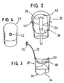
- the eardrum 20 is tightly connected to one in the embodiment shown according to the figures, two-part housing, specifically it is connected to a transmission part 22.
- This is essentially tubular. It has a substantially cylindrical area, which in figure 2 is shown below and an expanding from this Area that essentially runs on a conical surface. The diameter the cylindrical area is about 8 mm, the widening The area has corresponding dimensions of approximately 11 mm.
- FIG. 1 shows that the eardrum 20 is in one plane runs at an angle of 35 ° to a longitudinal axis 23 of the transmission part 22. Due to the inclination of the eardrum 20, the eardrum 20 a larger area than the normal ear.
- a second ossicle part 24 is permanently attached on the inside of the eardrum 20, preferably in the center of the area.
- An embodiment is a commercially available Richards ossicle replacement GmbH used. He has a ball joint near the eardrum 20, underneath there is a hollow shaft to hold one more to be discussed first part of the ossicle.
- the second ossicle part 24 runs below the ball joint centered on the central axis of the transmission part 22nd
- a coupling part 28 also belongs to the housing slightly smaller than the transmission part 22 and together with this trained, the two parts simply, tightly and permanently connected can be, especially by plugging in the longitudinal direction and Glue.
- the coupling part 28 is essentially cylindrical Diameter is also about 6 mm. It has a free end area 30, which has a course which corresponds to the respective individual relief of the The timpani wall of a wearer of the middle ear prosthesis is reproduced as precisely as possible is. The resulting individual course is special shown in Figure 3.
- the patent application "Device for mechanical scanning and recording the course of the timpani wall of a middle ear "from the same applicant and from the same filing date referenced, the disclosure content of this application becomes the subject made the disclosure of the present application.
- the free end region 30 is accordingly designed to be precise the timpani wall 32 rests, as can be seen from FIG. 1. To this A hermetically sealed closure is possible at this point, it low-viscosity fastening and sealing material can be used to the connection between the free end region 30 and the tympanic wall 32 to realize.
- a holding device 34 for the first ossicle part 26 provided in the coupling part 28 .
- the latter is designed as a thin gold wire that through a very small, artificially created opening 36 in a stapes footplate 38 extends straight through and thus with its lower, protrudes into the inner ear 40.
- the holding device 34 is a substantially diagonal Wire on which the first ossicle part 26 is or can be fixed is.
- the middle ear prosthesis is for the connection of the two ossicle parts 24, 26 and also for severing the holding device 34 requires access to the interior.
- Other Constructions without such access are possible.
- a window 42 through a cover plate 44 can be closed. It is shown in Figure 4.
- suitable mechanical holding means are provided around the cover plate 44 precise and also close to the transmission part 22 and the coupling part 28 to be able to determine.
- mandrels 46 are in the exemplary embodiment shown provided for fixing the cover plate 44, on the coupling part 28 a groove 48 for receiving the cover plate 44 through a projection educated.
- the coupling part 28 also preferably has in its upper area a recess 50, which is also used as a lower window recess referred to as.
- the cover plate 44 has a connection 52. It is for a hose 54 is provided, both of which can also be seen in FIG. 1.
- the Hose 54 leads to an inner part 56 of a pressure compensation device.
- This inner part 56 is designed as a can-shaped housing, it has two chambers, namely an outer chamber 58 and an inner chamber 60. Both are hermetically separated from each other by a very flexible membrane 62. In another version, they are through a fine filter, the is also tight against bacteria and microbes, but is permeable to air, separated from each other. Hollow fiber filters in particular come here as fine filters in question.
- the outer chamber 58 with an outer part is connected via a further hose 64 66 connected. It is anchored in a bone 76 and partially from accessible from outside, see skin 78. A construction is used here, as it is similar to so-called bone-conductive hearing aids.
- the outer part 66 has a recess 68 into which a filter 70 is inserted. This is preferably interchangeable.
- the filter 70 prevents water, Coarse dirt etc. can get into the hose 64.
- the barrier against Germs and the like are replaced by membrane 62 or that in their place pedaling fine filter reached.
- the material for the parts 22, 26, 28 and 44 and 56, 66 comes in particular Titanium into consideration.
- a Housing with an artificial eardrum 20 inserted into the housing corresponds to the first embodiment.
- a ferromagnetic core 82 in particular a core made of a Ferrite material is arranged.
- a coil 84 connected to the housing is applied outside the core 82.
- the second ossicle part 24 is made of a plastic or a other, non-conductive material. Form coil 84 and core 82 together an electrodynamic drive.
- the coil 84 is over a Lead 86 and optionally with the interposition of an implanted Amplifier 88 connected to a secondary coil 90 of a transformer.
- the secondary coil 90 is located below the skin 78 while the associated primary coil 92 is located outside the skin 78.
- the primary coil 92 is connected to the output of a hearing aid 94.
- the device installed in or receives the hearing aid 94 associated microphone sound information. They are in the hearing aid 94 strengthened and, if necessary, processed.
- the amplified signals are fed to the primary coil 92. From there they are transferred to the secondary coil 90 and thus transferred to the coil 84.
- transformer 90 To improve power transmission within transformer 90, 92 it is advisable to reduce the sound information to a implement high frequency for example of one megahertz. This happens Similar to the carrier frequency technology in telephone systems or in a corresponding one Wise.
- the movement of the Transfer the eardrum 20 to the two ossicular parts 24, 26 there are So two motion drives before.
- the ossicle parts 24, 26 through the eardrum 20 and thus directly through the eardrum 20 reaching sound moves, on the other hand by the above electrodynamic drive.
- the electrodynamic drive can only for certain frequency ranges, for example only the high frequency range, support the movement.
- hearing loss is preferred, which is only in certain frequency ranges is present, balanced.
- the electrodynamic drive can also be active in the entire frequency range.
- the housing is now only in one piece, it exists only from the coupling part 28 in which the window 42 is provided which is covered by the cover plate 44. Instead of an eardrum 20, the housing is firmly closed at the end region that the free end region 30 is opposite. So the housing is essentially cup-shaped. The closure at the end area can be used as a window instead of drawn window 42 serve.
- first ossicle part 26 Only a first ossicle part 26 is also provided, a second ossicle part eliminated.
- the first part of the ossicle is over a part running across it piezoelectric element 96 with the inner wall of the coupling part 28 connected.
- a bracket 98 is provided here.
- the piezoelectric Element 96 has the shape of an elongated plate, here as a double plate is executed. With appropriate electrical stimulation, it leads movements in the longitudinal direction of the first ossicle part 26. It's about that Lead 86 connected to the secondary coil 90 of a transformer.
- the transmission and connection with a hearing aid 94 takes place as in Exemplary embodiment according to FIG. 5.
Landscapes
- Health & Medical Sciences (AREA)
- Otolaryngology (AREA)
- Pulmonology (AREA)
- Cardiology (AREA)
- Oral & Maxillofacial Surgery (AREA)
- Transplantation (AREA)
- Engineering & Computer Science (AREA)
- Biomedical Technology (AREA)
- Heart & Thoracic Surgery (AREA)
- Vascular Medicine (AREA)
- Life Sciences & Earth Sciences (AREA)
- Animal Behavior & Ethology (AREA)
- General Health & Medical Sciences (AREA)
- Public Health (AREA)
- Veterinary Medicine (AREA)
- Prostheses (AREA)
Description
- FIG. 1:
- eine schnittbildliche Darstellung einer Mittelohrprothese mit angesetzter Druckausgleichvorrichtung,
- FIG. 2:
- eine perspektivische Darstellung eines Übertragungsteils mit Blick auf und durch ein Arbeitsfenster,
- FIG. 3:
- eine der Darstellung gemäß Figur 2 entsprechende Darstellung eines Ankopplungsteils,
- FIG. 4:
- eine Draufsicht auf eine Abdeckplatte,
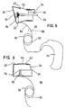
- FIG. 5:
- eine schnittbildliche Darstellung eines Gehäuses in ähnlicher Ansicht wie Figur 1, jedoch nunmehr mit zusätzlich einem elektrodynamischen Antrieb und mit einem über ein Übertragungsglied angeschlossenen externen Verstärker und
- FIG. 6:
- eine Darstellung ähnlich Figur 5, jedoch ohne Verstärker und nunmehr ohne Trommelfell, der Antrieb erfolgt ausschließlich piezoelektrisch.
Claims (10)
- Mittelohrprothese mit einem rohrförmigen Gehäuse, das ein Ankopplungsteil (28) aufweist, dadurch gekennzeichnet, dassdas Ankopplungsteil (28) einen freien Endbereich (30) aufweist, der ausgebildet ist für eine Anlage an der medialen Paukenwand (32) eines Ohrs,das Gehäuse eine in seinem Innenraum befindliche Halteeinrichtung (34) für ein durch eine kleine, künstlich geschaffene Öffnung (36) in einer Stapes-Fußplatte (38) ragendes oder auf dieser Fußplatte aufsetzendes Ossikelteil (26) aufweist,das Gehäuse mit einem Fenster (42) versehen ist, durch das die Halteeinrichtung (34) zugänglich ist undein Abdeckteil (44) für das Fenster (42) vorgesehen ist
- Mittelohrprothese nach Anspruch 1, dadurch gekennzeichnet, dass der freie Endbereich des Ankopplungsteils (28) einen Verlauf hat, der dem jeweiligen individuellen Relief eines Trägers der Mittelohrprothese möglichst genau nachgebildet ist.
- Mittelohrprothese nach Anspruch 1, dadurch gekennzeichnet, dass ein vorzugsweise künstliches Trommelfell (20) vorgesehen ist, das mit dem Gehäuse verbunden ist, dass ein zweites Ossikelteil (24) vorgesehen ist, das mit der Innenfläche des Trommelfells (20) verbunden ist und dass das erste Ossikelteil (26) und das zweite Ossikelteil (24) Mittel für ihre Verbindung aufweisen.
- Mittelohrprothese nach Anspruch 3, dadurch gekennzeichnet, dass das Trommelfell (20) in einem Winkel von 85° bis 40°, vorzugsweise 53°, zur Achse des Übertragungsteil (22) verläuft, insbesondere, dass das Trommelfell (20) einen elliptischen Zuschnitt hat.
- Mittelohrprothese nach Anspruch 1, dadurch gekennzeichnet, dass ein elektrischer Antrieb, insbesondere ein elektrodynamischer oder piezoelektrischer Antrieb vorgesehen ist, der im Gehäuse angeordnet ist und mit dem ersten Ossikelteil (26) bewegungsverbunden ist.
- Mittelohrprothese nach Anspruch 1, dadurch gekennzeichnet, dass am Gehäuse Verbindungsmittel (72, 74) für die mechanische Befestigung des Gehäuses an einem Knochen, insbesondere am Felsenbein des Trägers der Mittelohrprothese, vorgesehen sind.
- Mittelohrprothese nach Anspruch 1, dadurch gekennzeichnet, dass das erste Ossikelteil (26) mit der Halteeinrichtung (34) lösbar verbunden ist.
- Mittelohrprothese nach Anspruch 1, dadurch gekennzeichnet, dass bei dichtem Abschluß am freien Endbereich (30) des Ankopplungsteils (28), insbesondere beim Einsatz an der Paukenwand (32) eines Ohrs, der Innenraum des Gehäuses keimdicht, vorzugsweise luftdicht abgeschlossen ist.
- Mittelohrprothese nach Anspruch 1, dadurch gekennzeichnet, dass der Innenraum des Gehäuses über einen Schlauch (54) mit einer Druckausgleichsvorrichtung verbunden ist.
- Mittelohrprothese nach Anspruch 1, dadurch gekennzeichnet, dass das Gehäuse aus dem Ankopplungsteil (28) und einem Übertragungsteil (22) zusammengesetzt ist.
Applications Claiming Priority (3)
| Application Number | Priority Date | Filing Date | Title |
|---|---|---|---|
| DE19700813 | 1997-01-13 | ||
| DE19700813A DE19700813A1 (de) | 1997-01-13 | 1997-01-13 | Mittelohrprothese |
| PCT/DE1998/000073 WO1998030175A1 (de) | 1997-01-13 | 1998-01-10 | Mittelohrprothese |
Publications (2)
| Publication Number | Publication Date |
|---|---|
| EP1017337A1 EP1017337A1 (de) | 2000-07-12 |
| EP1017337B1 true EP1017337B1 (de) | 2003-05-07 |
Family
ID=7817217
Family Applications (1)
| Application Number | Title | Priority Date | Filing Date |
|---|---|---|---|
| EP98902948A Expired - Lifetime EP1017337B1 (de) | 1997-01-13 | 1998-01-10 | Mittelohrprothese |
Country Status (8)
| Country | Link |
|---|---|
| US (1) | US6241767B1 (de) |
| EP (1) | EP1017337B1 (de) |
| JP (1) | JP2001507964A (de) |
| AT (1) | ATE239428T1 (de) |
| AU (1) | AU734619B2 (de) |
| CA (1) | CA2277864A1 (de) |
| DE (2) | DE19700813A1 (de) |
| WO (1) | WO1998030175A1 (de) |
Families Citing this family (34)
| Publication number | Priority date | Publication date | Assignee | Title |
|---|---|---|---|---|
| US7025785B1 (en) | 2003-12-30 | 2006-04-11 | University Of South Florida | Incus replacement prosthesis |
| US7867160B2 (en) | 2004-10-12 | 2011-01-11 | Earlens Corporation | Systems and methods for photo-mechanical hearing transduction |
| US7668325B2 (en) | 2005-05-03 | 2010-02-23 | Earlens Corporation | Hearing system having an open chamber for housing components and reducing the occlusion effect |
| US8295523B2 (en) | 2007-10-04 | 2012-10-23 | SoundBeam LLC | Energy delivery and microphone placement methods for improved comfort in an open canal hearing aid |
| JP4599563B2 (ja) * | 2005-11-04 | 2010-12-15 | 国立大学法人 岡山大学 | 外耳道再建用成形品及びその製造方法 |
| GB2449114A (en) | 2007-05-11 | 2008-11-12 | Sentient Medical Ltd | Middle ear implant with piezoelectric actuator acting on stapes footplate |
| WO2009049320A1 (en) | 2007-10-12 | 2009-04-16 | Earlens Corporation | Multifunction system and method for integrated hearing and communiction with noise cancellation and feedback management |
| WO2009155358A1 (en) | 2008-06-17 | 2009-12-23 | Earlens Corporation | Optical electro-mechanical hearing devices with separate power and signal components |
| US8396239B2 (en) | 2008-06-17 | 2013-03-12 | Earlens Corporation | Optical electro-mechanical hearing devices with combined power and signal architectures |
| WO2009155361A1 (en) | 2008-06-17 | 2009-12-23 | Earlens Corporation | Optical electro-mechanical hearing devices with combined power and signal architectures |
| DK3509324T3 (da) | 2008-09-22 | 2023-10-02 | Earlens Corp | Balancerede armaturindretninger og fremgangsmåder til at høre |
| DK2438768T3 (en) | 2009-06-05 | 2016-06-06 | Earlens Corp | Optically coupled acoustically mellemøreimplantatindretning |
| US9544700B2 (en) | 2009-06-15 | 2017-01-10 | Earlens Corporation | Optically coupled active ossicular replacement prosthesis |
| US8401214B2 (en) | 2009-06-18 | 2013-03-19 | Earlens Corporation | Eardrum implantable devices for hearing systems and methods |
| CN102640435B (zh) | 2009-06-18 | 2016-11-16 | 伊尔莱茵斯公司 | 光学耦合的耳蜗植入系统及方法 |
| CN102598714A (zh) * | 2009-06-22 | 2012-07-18 | 音束有限责任公司 | 圆窗耦合的听力系统和方法 |
| WO2011005479A2 (en) | 2009-06-22 | 2011-01-13 | SoundBeam LLC | Optically coupled bone conduction systems and methods |
| GB0910906D0 (en) * | 2009-06-24 | 2009-08-05 | Sentient Medical Ltd | Coupling apparatus |
| US8715154B2 (en) | 2009-06-24 | 2014-05-06 | Earlens Corporation | Optically coupled cochlear actuator systems and methods |
| WO2010151636A2 (en) | 2009-06-24 | 2010-12-29 | SoundBeam LLC | Optical cochlear stimulation devices and methods |
| WO2012088187A2 (en) | 2010-12-20 | 2012-06-28 | SoundBeam LLC | Anatomically customized ear canal hearing apparatus |
| KR101519724B1 (ko) | 2013-09-09 | 2015-05-12 | 박정환 | 소리 전달과정 모식장치 |
| US10034103B2 (en) | 2014-03-18 | 2018-07-24 | Earlens Corporation | High fidelity and reduced feedback contact hearing apparatus and methods |
| EP3169396B1 (de) | 2014-07-14 | 2021-04-21 | Earlens Corporation | Gleitende vorspannung und spitzenunterdrückung für optische hörgeräte |
| US9924276B2 (en) | 2014-11-26 | 2018-03-20 | Earlens Corporation | Adjustable venting for hearing instruments |
| EP3355801B1 (de) | 2015-10-02 | 2021-05-19 | Earlens Corporation | Angepasste gehörgangvorrichtung zur arzneimittelabgabe |
| US10492010B2 (en) | 2015-12-30 | 2019-11-26 | Earlens Corporations | Damping in contact hearing systems |
| US11350226B2 (en) | 2015-12-30 | 2022-05-31 | Earlens Corporation | Charging protocol for rechargeable hearing systems |
| US10306381B2 (en) | 2015-12-30 | 2019-05-28 | Earlens Corporation | Charging protocol for rechargable hearing systems |
| US20180077504A1 (en) | 2016-09-09 | 2018-03-15 | Earlens Corporation | Contact hearing systems, apparatus and methods |
| WO2018093733A1 (en) | 2016-11-15 | 2018-05-24 | Earlens Corporation | Improved impression procedure |
| WO2019173470A1 (en) | 2018-03-07 | 2019-09-12 | Earlens Corporation | Contact hearing device and retention structure materials |
| WO2019199680A1 (en) | 2018-04-09 | 2019-10-17 | Earlens Corporation | Dynamic filter |
| JP7579807B2 (ja) * | 2019-04-30 | 2024-11-08 | オトネクサス メディカル テクノロジーズ, インコーポレイテッド | 鼓膜をシミュレートするためのシステムおよび方法 |
Family Cites Families (10)
| Publication number | Priority date | Publication date | Assignee | Title |
|---|---|---|---|---|
| US2191832A (en) * | 1939-02-13 | 1940-02-27 | Pohlman Augustus Grote | Auditory apparatus |
| US3712962A (en) * | 1971-04-05 | 1973-01-23 | J Epley | Implantable piezoelectric hearing aid |
| NL7612657A (nl) * | 1976-11-15 | 1978-05-17 | Grote Johannes J | Kunstmiddenoor en een werkwijze voor het vervaardigen hiervan. |
| DE2905183C3 (de) | 1979-02-10 | 1987-12-03 | Friedrichsfeld GmbH Keramik- und Kunststoffwerke, 6800 Mannheim | Einstückige Mittelohrprothese |
| DE2937842C3 (de) | 1979-09-19 | 1988-09-08 | Friedrichsfeld GmbH Keramik- und Kunststoffwerke, 6800 Mannheim | Einstückige Mittelohrprothese |
| US4676796A (en) | 1985-05-24 | 1987-06-30 | University Of Florida | Middle ear prosthesis |
| DE3707161A1 (de) | 1987-03-06 | 1988-09-15 | Fleischer Gerald | Ohrprothese |
| US4957507A (en) * | 1987-12-14 | 1990-09-18 | Edmundas Lenkauskas | Wire spring prosthesis for ossicular reconstruction |
| IT1248737B (it) * | 1990-06-07 | 1995-01-26 | Franco Beoni | Protesi di orecchio medio |
| DE4407847A1 (de) * | 1993-03-10 | 1994-09-22 | Fleischer Gerald | Mittelohr-Prothese |
-
1997
- 1997-01-13 DE DE19700813A patent/DE19700813A1/de not_active Withdrawn
-
1998
- 1998-01-10 EP EP98902948A patent/EP1017337B1/de not_active Expired - Lifetime
- 1998-01-10 US US09/341,791 patent/US6241767B1/en not_active Expired - Fee Related
- 1998-01-10 AT AT98902948T patent/ATE239428T1/de not_active IP Right Cessation
- 1998-01-10 CA CA002277864A patent/CA2277864A1/en not_active Abandoned
- 1998-01-10 JP JP53046498A patent/JP2001507964A/ja not_active Ceased
- 1998-01-10 DE DE59808296T patent/DE59808296D1/de not_active Expired - Fee Related
- 1998-01-10 WO PCT/DE1998/000073 patent/WO1998030175A1/de not_active Ceased
- 1998-01-10 AU AU59814/98A patent/AU734619B2/en not_active Ceased
Also Published As
| Publication number | Publication date |
|---|---|
| JP2001507964A (ja) | 2001-06-19 |
| EP1017337A1 (de) | 2000-07-12 |
| DE59808296D1 (de) | 2003-06-12 |
| CA2277864A1 (en) | 1998-07-16 |
| ATE239428T1 (de) | 2003-05-15 |
| AU5981498A (en) | 1998-08-03 |
| AU734619B2 (en) | 2001-06-21 |
| US6241767B1 (en) | 2001-06-05 |
| WO1998030175A1 (de) | 1998-07-16 |
| DE19700813A1 (de) | 1998-07-16 |
Similar Documents
| Publication | Publication Date | Title |
|---|---|---|
| EP1017337B1 (de) | Mittelohrprothese | |
| EP1067820B1 (de) | Anordnung zum mechanischen Ankoppeln eines Treibers an eine Ankoppelstelle der Ossikelkette | |
| DE19935029C2 (de) | Implantierbare Anordnung zum mechanischen Ankoppeln eines Treiberteils an eine Ankoppelstelle | |
| DE19948375B4 (de) | Anordnung zum mechanischen Ankoppeln eines Treibers an eine Ankoppelstelle der Ossikelkette | |
| EP0812577B1 (de) | Implantierbares Positionier- und Fixiersystem für aktorische und sensorische Implantate | |
| DE69024408T2 (de) | Einrichtung zur Regulierung des Druckes im äusseren Ohrkanal und Einrichtung zur Unterdrückung von Tinnitus | |
| EP1042991B1 (de) | Implantierbares Positionier- und Fixiersystem für aktorische und sensorische Implantate | |
| EP1345471B1 (de) | Otoplastik für Hinter-dem-Ohr(HdO)-Hörgeräte | |
| DE69618466T2 (de) | Stüzelement zur implantation in knochengewebe | |
| DE19948336C2 (de) | Anordnung zum Ankoppeln eines Treibers an eine Ankoppelstelle der Ossikelkette | |
| DE10047388C1 (de) | Mindestens teilweise implantierbares Hörsystem | |
| EP0901779A2 (de) | Anordnung zum Einstellen und Fixieren der Relativlage zweier Elemente eines aktiven oder passiven Hör-Implantats | |
| EP1173044A2 (de) | System zur Rehabilitation einer Hörstörung | |
| EP1191815A2 (de) | Mindestens teilimplantierbares Hörsystem mit direkter mechanischer Stimulation eines lymphatischen Raums des Innenohres | |
| EP1179969A2 (de) | Mindestens teilweise implantierbares Hörsystem | |
| EP1054573A2 (de) | Vorrichtung zum mechanischen Ankoppeln eines in einer Mastoidhöhle implantierbaren elektromechanischen Hörgerätewandlers | |
| EP0281047A1 (de) | Mittelohr-Prothese | |
| DE60015724T2 (de) | Mittelohrimplantat | |
| EP0544677B1 (de) | Elektromagnetisches mittelohr-hörhilfsgerät | |
| DE102009051057B4 (de) | Implantierbarer Sensor-Aktor-Wandlerbaustein für die apparative Hörrehabilitation im Mittelohr | |
| EP0951261B1 (de) | Druckausgleichvorrichtung als prothetischer ersatz für eine eustachische röhre | |
| DE102015117272B4 (de) | Knochenleitungs-Hörgerät und Head-Set mit einem derartigen Knochenleitungs-Hörgerät | |
| DE19718223A1 (de) | Tinnitus-Masker | |
| DE102007059748A1 (de) | Positionierungsvorrichtung für aktive Innenohrimplantate | |
| DE29901585U1 (de) | Mittelohrimplantat |
Legal Events
| Date | Code | Title | Description |
|---|---|---|---|
| PUAI | Public reference made under article 153(3) epc to a published international application that has entered the european phase |
Free format text: ORIGINAL CODE: 0009012 |
|
| 17P | Request for examination filed |
Effective date: 19990813 |
|
| AK | Designated contracting states |
Kind code of ref document: A1 Designated state(s): AT BE CH DE FR GB IT LI NL SE |
|
| GRAH | Despatch of communication of intention to grant a patent |
Free format text: ORIGINAL CODE: EPIDOS IGRA |
|
| GRAH | Despatch of communication of intention to grant a patent |
Free format text: ORIGINAL CODE: EPIDOS IGRA |
|
| GRAA | (expected) grant |
Free format text: ORIGINAL CODE: 0009210 |
|
| AK | Designated contracting states |
Designated state(s): AT BE CH DE FR GB IT LI NL SE |
|
| PG25 | Lapsed in a contracting state [announced via postgrant information from national office to epo] |
Ref country code: NL Free format text: LAPSE BECAUSE OF FAILURE TO SUBMIT A TRANSLATION OF THE DESCRIPTION OR TO PAY THE FEE WITHIN THE PRESCRIBED TIME-LIMIT Effective date: 20030507 Ref country code: IT Free format text: LAPSE BECAUSE OF FAILURE TO SUBMIT A TRANSLATION OF THE DESCRIPTION OR TO PAY THE FEE WITHIN THE PRESCRIBED TIME-LIMIT;WARNING: LAPSES OF ITALIAN PATENTS WITH EFFECTIVE DATE BEFORE 2007 MAY HAVE OCCURRED AT ANY TIME BEFORE 2007. THE CORRECT EFFECTIVE DATE MAY BE DIFFERENT FROM THE ONE RECORDED. Effective date: 20030507 Ref country code: GB Free format text: LAPSE BECAUSE OF FAILURE TO SUBMIT A TRANSLATION OF THE DESCRIPTION OR TO PAY THE FEE WITHIN THE PRESCRIBED TIME-LIMIT Effective date: 20030507 |
|
| REG | Reference to a national code |
Ref country code: GB Ref legal event code: FG4D Free format text: NOT ENGLISH |
|
| REG | Reference to a national code |
Ref country code: CH Ref legal event code: EP |
|
| REF | Corresponds to: |
Ref document number: 59808296 Country of ref document: DE Date of ref document: 20030612 Kind code of ref document: P |
|
| PG25 | Lapsed in a contracting state [announced via postgrant information from national office to epo] |
Ref country code: SE Free format text: LAPSE BECAUSE OF FAILURE TO SUBMIT A TRANSLATION OF THE DESCRIPTION OR TO PAY THE FEE WITHIN THE PRESCRIBED TIME-LIMIT Effective date: 20030807 |
|
| NLV1 | Nl: lapsed or annulled due to failure to fulfill the requirements of art. 29p and 29m of the patents act | ||
| GBT | Gb: translation of ep patent filed (gb section 77(6)(a)/1977) |
Effective date: 20031021 |
|
| REG | Reference to a national code |
Ref country code: FR Ref legal event code: RN |
|
| PG25 | Lapsed in a contracting state [announced via postgrant information from national office to epo] |
Ref country code: AT Free format text: LAPSE BECAUSE OF NON-PAYMENT OF DUE FEES Effective date: 20040110 |
|
| PG25 | Lapsed in a contracting state [announced via postgrant information from national office to epo] |
Ref country code: LI Free format text: LAPSE BECAUSE OF NON-PAYMENT OF DUE FEES Effective date: 20040131 Ref country code: CH Free format text: LAPSE BECAUSE OF NON-PAYMENT OF DUE FEES Effective date: 20040131 Ref country code: BE Free format text: LAPSE BECAUSE OF NON-PAYMENT OF DUE FEES Effective date: 20040131 |
|
| PLBE | No opposition filed within time limit |
Free format text: ORIGINAL CODE: 0009261 |
|
| STAA | Information on the status of an ep patent application or granted ep patent |
Free format text: STATUS: NO OPPOSITION FILED WITHIN TIME LIMIT |
|
| REG | Reference to a national code |
Ref country code: FR Ref legal event code: FC |
|
| 26N | No opposition filed |
Effective date: 20040210 |
|
| EN | Fr: translation not filed | ||
| PG25 | Lapsed in a contracting state [announced via postgrant information from national office to epo] |
Ref country code: FR Free format text: LAPSE BECAUSE OF FAILURE TO SUBMIT A TRANSLATION OF THE DESCRIPTION OR TO PAY THE FEE WITHIN THE PRESCRIBED TIME-LIMIT Effective date: 20040514 |
|
| ET | Fr: translation filed | ||
| BERE | Be: lapsed |
Owner name: *STENNERT EBERHARD Effective date: 20040131 |
|
| REG | Reference to a national code |
Ref country code: CH Ref legal event code: PL |
|
| REG | Reference to a national code |
Ref country code: GB Ref legal event code: 732E |
|
| REG | Reference to a national code |
Ref country code: FR Ref legal event code: TP |
|
| PGFP | Annual fee paid to national office [announced via postgrant information from national office to epo] |
Ref country code: GB Payment date: 20070102 Year of fee payment: 10 Ref country code: DE Payment date: 20070102 Year of fee payment: 10 |
|
| PGFP | Annual fee paid to national office [announced via postgrant information from national office to epo] |
Ref country code: FR Payment date: 20070102 Year of fee payment: 10 |
|
| GBPC | Gb: european patent ceased through non-payment of renewal fee |
Effective date: 20080110 |
|
| PG25 | Lapsed in a contracting state [announced via postgrant information from national office to epo] |
Ref country code: DE Free format text: LAPSE BECAUSE OF NON-PAYMENT OF DUE FEES Effective date: 20080801 |
|
| REG | Reference to a national code |
Ref country code: FR Ref legal event code: ST Effective date: 20081029 |
|
| PG25 | Lapsed in a contracting state [announced via postgrant information from national office to epo] |
Ref country code: GB Free format text: LAPSE BECAUSE OF FAILURE TO SUBMIT A TRANSLATION OF THE DESCRIPTION OR TO PAY THE FEE WITHIN THE PRESCRIBED TIME-LIMIT Effective date: 20080110 |
|
| PG25 | Lapsed in a contracting state [announced via postgrant information from national office to epo] |
Ref country code: FR Free format text: LAPSE BECAUSE OF FAILURE TO SUBMIT A TRANSLATION OF THE DESCRIPTION OR TO PAY THE FEE WITHIN THE PRESCRIBED TIME-LIMIT Effective date: 20080131 |