EP1017433B1 - Systeme de pompe a sang a limitation de debit - Google Patents
Systeme de pompe a sang a limitation de debit Download PDFInfo
- Publication number
- EP1017433B1 EP1017433B1 EP98920865.7A EP98920865A EP1017433B1 EP 1017433 B1 EP1017433 B1 EP 1017433B1 EP 98920865 A EP98920865 A EP 98920865A EP 1017433 B1 EP1017433 B1 EP 1017433B1
- Authority
- EP
- European Patent Office
- Prior art keywords
- pump
- flow
- impeller
- pressure
- pumping system
- Prior art date
- Legal status (The legal status is an assumption and is not a legal conclusion. Google has not performed a legal analysis and makes no representation as to the accuracy of the status listed.)
- Expired - Lifetime
Links
Images



Classifications
-
- A—HUMAN NECESSITIES
- A61—MEDICAL OR VETERINARY SCIENCE; HYGIENE
- A61M—DEVICES FOR INTRODUCING MEDIA INTO, OR ONTO, THE BODY; DEVICES FOR TRANSDUCING BODY MEDIA OR FOR TAKING MEDIA FROM THE BODY; DEVICES FOR PRODUCING OR ENDING SLEEP OR STUPOR
- A61M60/00—Blood pumps; Devices for mechanical circulatory actuation; Balloon pumps for circulatory assistance
- A61M60/40—Details relating to driving
- A61M60/403—Details relating to driving for non-positive displacement blood pumps
- A61M60/422—Details relating to driving for non-positive displacement blood pumps the force acting on the blood contacting member being electromagnetic, e.g. using canned motor pumps
-
- A—HUMAN NECESSITIES
- A61—MEDICAL OR VETERINARY SCIENCE; HYGIENE
- A61M—DEVICES FOR INTRODUCING MEDIA INTO, OR ONTO, THE BODY; DEVICES FOR TRANSDUCING BODY MEDIA OR FOR TAKING MEDIA FROM THE BODY; DEVICES FOR PRODUCING OR ENDING SLEEP OR STUPOR
- A61M60/00—Blood pumps; Devices for mechanical circulatory actuation; Balloon pumps for circulatory assistance
- A61M60/10—Location thereof with respect to the patient's body
- A61M60/122—Implantable pumps or pumping devices, i.e. the blood being pumped inside the patient's body
- A61M60/165—Implantable pumps or pumping devices, i.e. the blood being pumped inside the patient's body implantable in, on, or around the heart
- A61M60/178—Implantable pumps or pumping devices, i.e. the blood being pumped inside the patient's body implantable in, on, or around the heart drawing blood from a ventricle and returning the blood to the arterial system via a cannula external to the ventricle, e.g. left or right ventricular assist devices
-
- A—HUMAN NECESSITIES
- A61—MEDICAL OR VETERINARY SCIENCE; HYGIENE
- A61M—DEVICES FOR INTRODUCING MEDIA INTO, OR ONTO, THE BODY; DEVICES FOR TRANSDUCING BODY MEDIA OR FOR TAKING MEDIA FROM THE BODY; DEVICES FOR PRODUCING OR ENDING SLEEP OR STUPOR
- A61M60/00—Blood pumps; Devices for mechanical circulatory actuation; Balloon pumps for circulatory assistance
- A61M60/20—Type thereof
- A61M60/205—Non-positive displacement blood pumps
- A61M60/216—Non-positive displacement blood pumps including a rotating member acting on the blood, e.g. impeller
- A61M60/226—Non-positive displacement blood pumps including a rotating member acting on the blood, e.g. impeller the blood flow through the rotating member having mainly radial components
- A61M60/232—Centrifugal pumps
-
- A—HUMAN NECESSITIES
- A61—MEDICAL OR VETERINARY SCIENCE; HYGIENE
- A61M—DEVICES FOR INTRODUCING MEDIA INTO, OR ONTO, THE BODY; DEVICES FOR TRANSDUCING BODY MEDIA OR FOR TAKING MEDIA FROM THE BODY; DEVICES FOR PRODUCING OR ENDING SLEEP OR STUPOR
- A61M60/00—Blood pumps; Devices for mechanical circulatory actuation; Balloon pumps for circulatory assistance
- A61M60/40—Details relating to driving
- A61M60/403—Details relating to driving for non-positive displacement blood pumps
- A61M60/419—Details relating to driving for non-positive displacement blood pumps the force acting on the blood contacting member being permanent magnetic, e.g. from a rotating magnetic coupling between driving and driven magnets
-
- A—HUMAN NECESSITIES
- A61—MEDICAL OR VETERINARY SCIENCE; HYGIENE
- A61M—DEVICES FOR INTRODUCING MEDIA INTO, OR ONTO, THE BODY; DEVICES FOR TRANSDUCING BODY MEDIA OR FOR TAKING MEDIA FROM THE BODY; DEVICES FOR PRODUCING OR ENDING SLEEP OR STUPOR
- A61M60/00—Blood pumps; Devices for mechanical circulatory actuation; Balloon pumps for circulatory assistance
- A61M60/50—Details relating to control
- A61M60/508—Electronic control means, e.g. for feedback regulation
- A61M60/538—Regulation using real-time blood pump operational parameter data, e.g. motor current
- A61M60/546—Regulation using real-time blood pump operational parameter data, e.g. motor current of blood flow, e.g. by adapting rotor speed
-
- A—HUMAN NECESSITIES
- A61—MEDICAL OR VETERINARY SCIENCE; HYGIENE
- A61M—DEVICES FOR INTRODUCING MEDIA INTO, OR ONTO, THE BODY; DEVICES FOR TRANSDUCING BODY MEDIA OR FOR TAKING MEDIA FROM THE BODY; DEVICES FOR PRODUCING OR ENDING SLEEP OR STUPOR
- A61M60/00—Blood pumps; Devices for mechanical circulatory actuation; Balloon pumps for circulatory assistance
- A61M60/80—Constructional details other than related to driving
- A61M60/802—Constructional details other than related to driving of non-positive displacement blood pumps
- A61M60/804—Impellers
- A61M60/806—Vanes or blades
-
- A—HUMAN NECESSITIES
- A61—MEDICAL OR VETERINARY SCIENCE; HYGIENE
- A61M—DEVICES FOR INTRODUCING MEDIA INTO, OR ONTO, THE BODY; DEVICES FOR TRANSDUCING BODY MEDIA OR FOR TAKING MEDIA FROM THE BODY; DEVICES FOR PRODUCING OR ENDING SLEEP OR STUPOR
- A61M60/00—Blood pumps; Devices for mechanical circulatory actuation; Balloon pumps for circulatory assistance
- A61M60/80—Constructional details other than related to driving
- A61M60/855—Constructional details other than related to driving of implantable pumps or pumping devices
- A61M60/871—Energy supply devices; Converters therefor
- A61M60/873—Energy supply devices; Converters therefor specially adapted for wireless or transcutaneous energy transfer [TET], e.g. inductive charging
-
- A—HUMAN NECESSITIES
- A61—MEDICAL OR VETERINARY SCIENCE; HYGIENE
- A61M—DEVICES FOR INTRODUCING MEDIA INTO, OR ONTO, THE BODY; DEVICES FOR TRANSDUCING BODY MEDIA OR FOR TAKING MEDIA FROM THE BODY; DEVICES FOR PRODUCING OR ENDING SLEEP OR STUPOR
- A61M2205/00—General characteristics of the apparatus
- A61M2205/33—Controlling, regulating or measuring
- A61M2205/3331—Pressure; Flow
- A61M2205/3334—Measuring or controlling the flow rate
-
- A—HUMAN NECESSITIES
- A61—MEDICAL OR VETERINARY SCIENCE; HYGIENE
- A61M—DEVICES FOR INTRODUCING MEDIA INTO, OR ONTO, THE BODY; DEVICES FOR TRANSDUCING BODY MEDIA OR FOR TAKING MEDIA FROM THE BODY; DEVICES FOR PRODUCING OR ENDING SLEEP OR STUPOR
- A61M2205/00—General characteristics of the apparatus
- A61M2205/82—Internal energy supply devices
- A61M2205/8237—Charging means
- A61M2205/8243—Charging means by induction
-
- A—HUMAN NECESSITIES
- A61—MEDICAL OR VETERINARY SCIENCE; HYGIENE
- A61M—DEVICES FOR INTRODUCING MEDIA INTO, OR ONTO, THE BODY; DEVICES FOR TRANSDUCING BODY MEDIA OR FOR TAKING MEDIA FROM THE BODY; DEVICES FOR PRODUCING OR ENDING SLEEP OR STUPOR
- A61M60/00—Blood pumps; Devices for mechanical circulatory actuation; Balloon pumps for circulatory assistance
- A61M60/10—Location thereof with respect to the patient's body
- A61M60/122—Implantable pumps or pumping devices, i.e. the blood being pumped inside the patient's body
- A61M60/126—Implantable pumps or pumping devices, i.e. the blood being pumped inside the patient's body implantable via, into, inside, in line, branching on, or around a blood vessel
- A61M60/148—Implantable pumps or pumping devices, i.e. the blood being pumped inside the patient's body implantable via, into, inside, in line, branching on, or around a blood vessel in line with a blood vessel using resection or like techniques, e.g. permanent endovascular heart assist devices
-
- A—HUMAN NECESSITIES
- A61—MEDICAL OR VETERINARY SCIENCE; HYGIENE
- A61M—DEVICES FOR INTRODUCING MEDIA INTO, OR ONTO, THE BODY; DEVICES FOR TRANSDUCING BODY MEDIA OR FOR TAKING MEDIA FROM THE BODY; DEVICES FOR PRODUCING OR ENDING SLEEP OR STUPOR
- A61M60/00—Blood pumps; Devices for mechanical circulatory actuation; Balloon pumps for circulatory assistance
- A61M60/80—Constructional details other than related to driving
- A61M60/855—Constructional details other than related to driving of implantable pumps or pumping devices
- A61M60/89—Valves
- A61M60/898—Valves the blood pump being a membrane blood pump and the membrane acting as inlet valve
Definitions
- the present invention relates to the art of pumping devices and cardiac prosthesis. More particularly, the present invention relates to motor-driven rotodynamic pumps for use as blood pumps in the human body and to control systems and techniques for such blood pumps.
- the peripheral vascular resistance and venous "tone" are controlled by the body according to the needs of the body's organs. Blood vessels constrict (vasoconstriction) and expand (vasodilation) in response to neural impulses associated with blood demand required by the body's organs. This action results in pressure and flow variations within the circulatory system.
- the natural heart is the servant of the circulatory system and the amount of blood pumped is dependent on the requirements of the body. That is, the cardiac output (the volume of blood delivered by the heart within a given time period) is equal to the venous return (the volume of blood returning to the heart within that same time period).
- the human heart is characterized by intrinsic control that responds to changes in demand for blood flow by the circulatory system. Illustrative of this characteristic is the fact that extrinsic control implements are not necessary when a human heart is transplanted and no direct neural connection is required for the transplanted heart to assume the cardiac function in the host body.
- Rotodynamic pumps typically operate or are controlled to maintain a defined pressure difference between the pump inlet and outlet.
- pump controllers do this by maintaining a set impeller speed.
- the performance characteristics of a pump are often expressed by a performance curve which depicts the relationship between the pressure differential across the pump and the pump flow for a given pump operating speed.
- rotodynamic blood pumps as cardiac prosthesis presents unique problems with regard to the interaction between the pump and the human circulatory system.
- conventional rotodynamic pumps are not as apt to respond correctly to changes in pressure and flow induced by the human circulatory system. This is due in part to the fact that, unlike the natural human heart, rotodynamic pumps have no inherent sensitivity to inlet pressure (preload) or outlet pressure (afterload).
- preload inlet pressure
- outlet pressure afterload
- a five or ten mm-Hg preload pressure change has a different physiologic significance than an equal amount of afterload change.
- an inappropriately designed and/or controlled rotodynamic pump may urge flow through the system until the inlet pressure falls to a correspondingly low and perhaps dangerous level, where upstream vascular structures may collapse from lack of blood pressure.
- the outlet pressure becomes high, the inlet pressure might rise a similar amount, and, in extreme cases, the direction of flow might even reverse.
- the change which is compensatory from the pump's point of view, is potentially maladaptive relative to the needs of the physiologic system being supported.
- the degree of maladaptivity of the pump is an inherent result, in part, of the nature of the performance curve associated with known pump designs.
- the pump comprises a housing equipped with inlet and outlet fluid passages in communication with a pumping chamber.
- An impeller is received within the chamber for propelling the fluid from the inlet to the outlet.
- the impeller is coupled to a motor or other prime mover.
- the amount of fluid flow moved from pump inlet to pump outlet is proportional to the pressure differential maintained across the ports by the system being supported by the pump.
- the pumping system is configured to provide a steep, pressure/flow performance curve in the vicinity of the operating set point such that a change in flow is relatively small compared to the change in pressure; that is, the constant of proportionality ⁇ Q/ ⁇ P is small.
- the pump configuration is such that flow through the pump is limited in the presence of large pressure differentials across the pump, thereby preventing excess flow which might damage the physiologic system.
- the outlet fluid passage includes a flow restrictor, so configured as to contribute to the steepness of the pressure/flow curve of the pumping system.
- the resistance of the outflow conduit connecting the pump to the physiologic system is configured to partially insulate the pump outlet from the effects of pressure changes in the receiving end of the physiologic system. This results in the flow output of the pump system remaining closer to the mean set point over the full range of circulatory pressures.
- the motor and its energy supply are controlled so that a decrease in load represented by falling flow results in an increase in the rotational speed of the impeller.
- This increases the pressure capability of the pump, improving its ability to deliver and control flow.
- An increase in flow has an exactly opposite effect.
- a switch permits the set point for the flow to be selected to suit the needs of different patients, or one patient during different phases of recovery.
- a major benefit of the invention is the ability of the pumping system to maintain flow in a narrow range, safe and satisfactory for the served system, without the use of external sensors and control loops. Another benefit is the potential to shift the mean set point of flow by simple and reliable means. Other benefits and advantages for the subject invention will become apparent to those skilled in the art upon a reading and understanding of the specification.
- FIGURE 1 shows block diagram of a blood pumping system according to the present invention.
- the human physiologic system is represented by block 12 and interfaces with pump 14 via flow receiving point 20 and flow delivery point 18.
- flow delivery point 18 may be a cannulation of the atrium or ventricle of the natural heart.
- Inflow conduit 22 may be a fluid carrying duct connecting the cannulation point to the inlet port of the pump.
- Outflow conduit 24 is another fluid carrying duct that connects pump outlet port to the flow receiving point 20. With a blood pump system, this point would usually be an anastomosis to a major artery.
- the function of the physiological control system 12 is well-known and a detailed discussion thereof is not necessary for an understanding of the present invention. It is sufficient to note that the physiological control system 12 results in pressure and flow variations at the inlet and outlet of the pump which may occur independently of one another.
- Energy input regulator 28 is a means to control the energy input to the prime mover of the pump, so as to facilitate control of pump 14.
- the prime mover is preferably an electric motor, and the regulator controls the voltage, frequency, or current of electricity supplied to the motor.
- prime movers such as hydraulic or pneumatic motors, or thermal systems, which have parameters analogous to electric voltage, frequency, and current, could be adapted as prime movers of this system.
- Energy transmission system 26 serves to conduct the power to energy input regulator 28 from the principal energy supply 16.
- Energy transmission system 26 may be a simple cable or conduit, or an electrical transformer-like transcutaneous transmission system.
- Storage battery 30, permits continuous power to energy input regulator 28 during transient interruption of the energy transmission system, and may include recharging provisions.
- Energy transmission system 26, principal energy supply 16 and battery 30 may comprise implements that are well-known in the art and a detailed discussion thereof is not necessary for an understanding of the present invention.
- FIGURE 2 depicts performance curves corresponding to three pump operating speeds.
- Curve 40 represents a nominal operating speed performance curve at which the pumping system is characterized by a maximum output pressure rise or "shut off" pressure 41 corresponding to a zero flow condition.
- the pumping system is configured to provide a performance curve which increases in steepness as flow increases, with a very steep slope S through the nominal operating point 42.
- this slope -- the change in flow rate divided by the change in pressure differential -- is on the order of about -3% or less (liters-per-minute/mm-Hg) such that, at the nominal operating set point of the pump, a change in pressure of about 50 mm-Hg between the pump inlet and outlet produces a change in flow of no more than 1 liter-per-minute.
- the configuration of the pumping system limits the ability of the pumping system to pass additional flow, hence preventing a significant increase in flow despite the change in applied pressure differential. In the case of an increased applied pressure, as flow drops, an opposite change in impeller characteristics would compensate for the effect of the external pressure, again holding the flow change within a limited band.
- maximum operating speed performance curve 50 banding the nominal rotational speed 40 are maximum operating speed performance curve 50 and minimum operating speed performance curve 51.
- a maximum expected imposed pressure rise 52 extrapolated to the low tolerance speed curve 51, yields a minimum flow 53.
- the nominal pressure 54 and nominal rpm 40 yield a nominal flow 55.
- Minimum pressure 56 and maximum rpm 50 cooperate to produce maximum flow 57.
- the pumping system is configured such that the flow excursions around the nominal operating point 42 are never so high, or low, as to cause damage to the system.
- the steepness of the performance curve therefore operates to reduce the flow increase or decrease associated with a given change in the pressure differential across the pumping system.
- the absolute values of these flows will be application dependent.
- the acceptable nominal and limit flows would depend on the size, sex, and age of the patient and what, if any, flow was still produced by the damaged natural heart. As an example, in a given human, a natural heart limited to an output of 2.5 liters/minute would result in severe impairment, and a poor quality of life.
- a ventricle assist device providing 4 liters/minute additional flow would result in a normal resting cardiac output. If the applied pressure rose, and assist device flow fell to 3 liters/minute, life would be maintained until treatment could be obtained, even if the natural heart fails completely; with some residual ventricular function, the patient could be quite comfortable with the summed flows. If pressure fell, and the pump flow increased to 6 liters/minute, the patient would not be seriously over pumped. If available filling flow had not increased, the assist device might divert some flow that otherwise would have gone through the natural aortic valve, but the blood in any case would reach the systemic circulation.
- Pump 14 includes a housing 100 which comprises two portions, impeller housing portion 102 and motor housing portion 104.
- a housing cover 106 is also provided.
- Housing 100 may be constructed from any biocompatible material, such as titanium.
- Housing cover 106 is secured to housing 100 using conventional fasteners (not shown) and a resilient seal 108 is provided therebetween.
- Housing cover 106 includes a generally hollow cylindrical axial extension 110 which houses stator 116 of motor 112 and includes a conical tip 111.
- Stator 116 includes a ferrous stack 118 and suitable conductors (not shown) for carrying current thereto.
- Stator 116 is secured within axial extension 110 by a threaded fastener 126 which also secures motor cover 124 in sealing engagement with housing 100 via O-ring 125.
- Motor 112 also includes an annular rotor 114 which is concentric with axial extension 110 and includes permanent magnet 120 therein. Rotor 114 constitutes a driver 122 for impeller 137 and is secured to the base 138 of impeller 137.
- Impeller housing portion 102 of housing 100 defines inlet 130 which communicates with impeller chamber 132 and annular chamber 134 situated around the outer periphery of impeller 137.
- Pump outlet 136 is a generally cylindrical passage which communicates with annular chamber 134.
- Impeller 137 which will be described below in more detail with reference to FIGURES 4A-4C , is configured to fit around conical tip 111 of axial extension 110.
- Impeller chamber 132 of housing 100 is shaped complementarily to the blades of impeller 137 to define flow passages from inlet 130 to annular chamber 134. In operation, rotation of impeller 137 imparts centrifugal force to the blood, thereby conveying it from inlet 130 outward into annular chamber 134 and pump outlet 136.
- impeller 137 comprises an annular base 138 which includes a circular recess 140 and impeller base perimeter 142. Extending from base 138 and fixed thereto are main impeller blades 144 and splitter blades 146, which extend between main blades 144 in alternating fashion. Splitter blades 146 give more guidance to the flow at the outer diameter of the impeller where the spacing between main blades 144 is relatively large, and also reduce the net flow area. As a result, the flow angle of blood better follows the blade angle, enhancing pump performance.
- FIGURE 4A which is a front view of impeller 137
- the impeller main blades 144 and splitter blades 146 are flat, with no curvature, and are provided with a tapered or curved outer edge 148.
- Tapered or curved outer edge 148 provides smooth velocity transitions and prevents separated blade wakes as impeller 137 rotates in the direction of arrow A. It will be appreciated, however, that curved blade designs may be suitable for some applications of the invention, provided that the desired performance characteristics of the pumping system as exemplified in FIGURE 2 are achieved.
- Main blades 144 and splitter blades 146 also include rounded inner edges 150 to preserve the integrity of the blood.
- Main blades 144 and splitter blades 146 are disposed at an angle THETA to the diameter of the base 138. Applicants have found that suitable results are obtained if THETA is between 35 and 75 degrees.
- the inner edges 150 of main blades 126 are angled with respect to the axis of the impeller. These angled edges 150 permit impeller 137 to accommodate conical tip 111 ( FIGURE 3 ) of axial extension 110. While the present embodiment has been described as a radial flow pump, it will be appreciated by anyone with reasonable skill in the art that similar performance goals could be met with mixed flow or axial flow pump configurations.
- FIGURE 5 illustrates flow restrictor in the form of an outflow conduit 24 which is suitable for use in a pumping system according to the present invention.
- Conduit 24 is provided with a pump connection end 60 and a flow receiving point end 61.
- the internal diameter 63 of the conduit is selected to be small, yet large enough to prevent flow velocities or patterns that may damage the blood.
- the length from inlet 60 to outlet 61 is selected such that, in combination with diameter 63, a specific resistance to flow can be obtained.
- FIGURE 6 An alternate approach to obtaining a useful resistance value is schematically shown in FIGURE 6 .
- This approach incorporates a device known as a Starling resistor.
- Flow enters tube 70 having a flaccid section 71.
- the flaccid section is surrounded by a case 72, which houses a fluid subjected to reference pressure P ref .
- Pressure P upstream is essentially the pressure at the pump outlet port. It is known that for this arrangement, the back pressure resisting flow in tube 70 will be the reference pressure P ref .
- the downstream pressure P downstream will be equal to the reference pressure P ref subtracted from the upstream pressure P upstream .
- the combination of a Starling resistor with an appropriate reference pressure P ref may be used to provide or enhance the flow-limiting characteristics of the pumping system as described above.
- FIGURE 7 illustrates a spring-loaded pressure reservoir suitable for providing the reference pressure P ref for the Starling resistor described above.
- the device comprises a spring 80 and bellows 82 which are secured to a piston 81.
- Reference pressure P ref will be equal to the force provided by spring 80 divided by the area of piston 81.
- a Starling resistor such as that illustrated in FIGURE 6 can be used on the pump inflow conduit 22 ( FIGURE 1 ) to prevent overpumping.
- the pressure P upstream would be the filling pressure upstream of the flow delivery point 18 ( FIGURE 1 ).
- Pressure P downstream would essentially be the pump inlet pressure.
- the reference pressure P ref would be selected to represent some safe minimum pressure level for pressure P upstream , perhaps -5.0 mmHg. If the pumping action resulted in the pressure P upstream falling below pressure P ref , the Starling resistor would collapse and flow would cease until pressure P upstream rose above pressure P ref .
- an over-pumping or under-pumping condition may be sensed according to the present invention by incorporating a deforming cross-section in the inflow or outflow conduit.
- a proximity switch 89 such as a magnetically operated reed switch, could be situated on the flaccid tube section 71 and used to sense under-pumping or over-pumping. Magnet 90 acts on the contact of switch 91. If the "flaccid" section 71 collapses or is expanded beyond predetermined limits, the switch 89 produces a signal to pump energy input regulator 28 which may be programmed or otherwise configured to alter the pump speed as appropriate.
- the electronics in pump energy input regulator 28 may include a time delay, or a positional hysteresis in the switch opening and closing, to ensure stability of operation by preventing hair-triggering between pump speed control values.
- FIGURE 9 A further modification to control technique for the energy input regulator 28 is illustrated in FIGURE 9 .
- a subcutaneous switch 160 such as a magnetically triggered reed switch, which permits the operator to modify the control characteristics of the pump from one rpm, current, or flow control algorithm to another.
- switch 160 is connected to the pump energy input regulator 28 by wires 161.
- the switch 160 is located subcutaneously in a patient and independent of other system components. Magnet 162 is brought into the vicinity of switch 160 by the patient or doctor to select between predetermined control configurations.
- flow may be limited to an acceptable range by algorithmic control of the power of the pump motor. It is known that the flow and the power corresponding to a given pump speed have a quantifiable relationship. By regulating the energy input to the pump motor according to a desired specific value, a more nearly constant pump flow may be obtained. If the inlet to outlet pressure difference falls, the tendency of the impeller in an uncontrolled pump would be to increase flow, resulting in an accompanying increased current demand by the motor. However, with power limited, the motor will slow or will operated within a predefined flow range. This will decrease the pump pressure capability and maintain pump flow within acceptable limits.
- Motor power may be controlled according to an algorithm that relies on the known relationships between pump flow and power in rotodynamic pump operation.
- the speed (rpm) and power of the motor are readily measured within the energy regulator-motor system by well known means. Therefore, by calibration of the system to determine the constants C1 and C2 and therefore the functional relationship between flow, rpm, and power, it is possible to control pump speed and power to hold a nearly constant flow, without ever measuring flow or pressure directly.
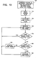
- FIGURE 10 is a flow chart for a control algorithm suitable for accomplishing pump control according to the present invention.
- the system is calibrated to determine the relationship between flow, speed and power. This may be accomplished by measuring these three parameters to determine the value of constants C1 and C2 in equations (1) - (4) above. Once determined, these constant values are stored for use in by the algorithm.
- the desired pump flow is input.
- pump power and speed are determined and used to determine a calculated value of pump outlet flow at 176.
- this value is compared to the desired pump flow value. If the pump outlet flow is equal to or within a predetermined tolerance of the desired flow, the algorithm returns to 174 where new measurements are made of pump power and speed. If Qoutput is not within a predetermined tolerance of Qdesired, the algorithm branches to 180 to determine whether the pump speed should be increased (184) or decreased (182). After the appropriate adjustment to motor speed is made, the algorithm returns to 174 to again measure pump power and speed.
- motor current rather than power, can be controlled, resulting in flow/pressure pressure relationship at constant current 200, as compared to the flow/pressure relationship at constant speed 201, for the same or a similar impeller.
- flow-limiting characteristics in accordance with the present invention may be achieved by appropriate modifications to the pump geometry itself, by implements such as flow restrictors or controllers added to the pumping system external of the pump, or by a combination of the two. Moreover, flow-limiting characteristics may be incorporated into the control system for the pump.
- the invention has been described with reference to the preferred embodiments. Obviously, modifications and alterations will occur to others upon the reading and understanding of the specification. It is our intention to include all such modifications and alterations insofar as they come within the scope of the appended claims.
Landscapes
- Health & Medical Sciences (AREA)
- Engineering & Computer Science (AREA)
- Heart & Thoracic Surgery (AREA)
- Cardiology (AREA)
- Life Sciences & Earth Sciences (AREA)
- Anesthesiology (AREA)
- Biomedical Technology (AREA)
- Hematology (AREA)
- Mechanical Engineering (AREA)
- Animal Behavior & Ethology (AREA)
- General Health & Medical Sciences (AREA)
- Public Health (AREA)
- Veterinary Medicine (AREA)
- Computer Networks & Wireless Communication (AREA)
- External Artificial Organs (AREA)
- Structures Of Non-Positive Displacement Pumps (AREA)
Claims (15)
- Pompe rotodynamique (14) comprenant :(a) un carter (100) qui définit une chambre, ainsi qu'une admission (130) et une évacuation (136) en communication fluidique avec ladite chambre (132/134) ;(b) une turbine (137) disposée à l'intérieur de la chambre (132) afin d'inciter le liquide à aller de l'admission (130) vers l'évacuation (136) ;(c) un couvercle de carter (106) ; et(d) un moteur (112) incluant un rotor annulaire (114) ;la turbine (137) comprend une base annulaire (138) qui inclut un renfoncement circulaire (140) ;
le couvercle de carter (106) inclut une extension axiale cylindrique creuse (110) et une extrémité conique (111), dans lequel l'extension axiale (110) loge un stator (116) du moteur (112) ;
le rotor annulaire (114) est concentrique par rapport à l'extension axiale (110), inclut un aimant permanent (120) dans celui-ci, et est fixé sur la base (138) de la turbine (137) et constitue un entraînement (122) pour la turbine (137) ; et
caractérisée en ce que
la turbine (137) étant configurée pour offrir une courbe de performances à forte pente de sorte qu'un débit de liquide dans la pompe (14) soit maintenu dans des limites définies sur une large plage de pressions différentielles appliquée à la pompe (14) et la courbe de performances (40) de la pompe (14) présente un changement de débit ne dépassant pas 1 litre par minute pour un changement de pression de 50 mm-Hg entre l'admission de pompe (130) et l'évacuation de pompe (136). - Pompe (14) selon la revendication 1, dans laquelle la courbe de performances (40) est linéaire en passant par un point de consigne de fonctionnement nominal (42) de la pompe (14).
- Pompe (14) selon la revendication 1, dans laquelle la turbine (137) comprend une pluralité d'aubes principales (144) et une pluralité d'aubes séparatrices (146), plus courtes que les aubes principales (144), disposées entre les aubes principales (144).
- Pompe (14) selon la revendication 1, dans laquelle la turbine (137) comprend une pluralité d'aubes plates (144/146).
- Système de pompage du sang, qui comprend :(a) une pompe rotodynamique (14) selon la revendication 1 ;(b) un entraînement (122) destiné à transmettre un mouvement de rotation à la turbine (137) ;(c) une source d'alimentation électrique destinée à fournir de l'énergie à l'entraînement (122) ;(d) un régulateur destiné à réguler l'énergie fournie par la source d'alimentation électrique à l'entraînement (122) afin de maintenir un courant constant ; et(e) un moyen de limitation de débit destiné à maintenir le débit dans la pompe (14) dans des limites prédéfinies sur une large plage de pressions différentielles dans toute la pompe (14) ;dans lequel la courbe de performances (40) de la pompe (14) présente un changement de débit ne dépassant pas 1 litre par minute pour un changement de pression de 50 mm-Hg entre l'admission de pompe (130) et l'évacuation de pompe (136) ; et
dans lequel le moyen de limitation de débit comprend une turbine (137) configurée pour offrir une courbe de performances à forte pente (40) de sorte qu'un débit de liquide dans la pompe est maintenu dans des limites définies sur une large plage de pressions différentielles appliquée. - Système de pompage selon la revendication 5, comprenant en outre un moyen de variation du point de consigne nominal (42) de la courbe de performances de sortie de la pompe (40).
- Système de pompage selon la revendication 6, dans lequel ladite turbine (137) inclut une pluralité d'aubes principales (144) et une pluralité d'aubes séparatrices (146), plus courtes que les aubes principales (144), disposées entre les aubes principales (144).
- Système de pompage selon la revendication 6, dans lequel ladite turbine (137) comprend une pluralité d'aubes plates (144/146).
- Système de pompage selon la revendication 6, dans lequel le moyen de limitation du débit comprend une résistance de débit en communication avec l'évacuation (136) de la pompe (14).
- Système de pompage selon la revendication 9, dans lequel la résistance de débit possède une valeur de résistance qui varie en fonction du débit.
- Système de pompage selon la revendication 6, le moyen de variation du point de consigne nominal (42) comprend un ordinateur exécutant un algorithme qui commande le point de consigne (42) selon la mesure du nombre de tours par minute ou de la puissance d'entrée de la pompe.
- Système de pompage de liquide selon la revendication 6, dans lequel le moyen de limitation du débit comprend un commutateur qui coopère avec un conduit à section transversale variable en communication fluidique avec l'évacuation (136) de la pompe (14), et qui génère un signal destiné au régulateur d'énergie.
- Système de pompage de liquide selon la revendication 14, dans lequel le moyen de limitation de débit est une résistance de débit sur l'admission de pompe (130).
- Système de pompage du sang selon la revendication 6, dans lequel le moyen de limitation du débit comprend un régulateur de puissance destiné à limiter la puissance fournie à l'entraînement de pompe (122).
- Système de pompage du sang selon la revendication 14, dans lequel le moyen de limitation de puissance comprend un régulateur de courant électrique.
Applications Claiming Priority (3)
| Application Number | Priority Date | Filing Date | Title |
|---|---|---|---|
| US93631797A | 1997-09-24 | 1997-09-24 | |
| US936317 | 1997-09-24 | ||
| PCT/US1998/008090 WO1999015212A1 (fr) | 1997-09-24 | 1998-05-12 | Systeme de pompe a sang a limitation de debit |
Publications (3)
| Publication Number | Publication Date |
|---|---|
| EP1017433A1 EP1017433A1 (fr) | 2000-07-12 |
| EP1017433A4 EP1017433A4 (fr) | 2006-06-14 |
| EP1017433B1 true EP1017433B1 (fr) | 2014-03-05 |
Family
ID=25468467
Family Applications (1)
| Application Number | Title | Priority Date | Filing Date |
|---|---|---|---|
| EP98920865.7A Expired - Lifetime EP1017433B1 (fr) | 1997-09-24 | 1998-05-12 | Systeme de pompe a sang a limitation de debit |
Country Status (6)
| Country | Link |
|---|---|
| US (1) | US7435059B2 (fr) |
| EP (1) | EP1017433B1 (fr) |
| JP (1) | JP2001517495A (fr) |
| AU (1) | AU7360798A (fr) |
| CA (1) | CA2304196A1 (fr) |
| WO (1) | WO1999015212A1 (fr) |
Cited By (13)
| Publication number | Priority date | Publication date | Assignee | Title |
|---|---|---|---|---|
| US10722631B2 (en) | 2018-02-01 | 2020-07-28 | Shifamed Holdings, Llc | Intravascular blood pumps and methods of use and manufacture |
| US11185677B2 (en) | 2017-06-07 | 2021-11-30 | Shifamed Holdings, Llc | Intravascular fluid movement devices, systems, and methods of use |
| US11511103B2 (en) | 2017-11-13 | 2022-11-29 | Shifamed Holdings, Llc | Intravascular fluid movement devices, systems, and methods of use |
| US11654275B2 (en) | 2019-07-22 | 2023-05-23 | Shifamed Holdings, Llc | Intravascular blood pumps with struts and methods of use and manufacture |
| US11724089B2 (en) | 2019-09-25 | 2023-08-15 | Shifamed Holdings, Llc | Intravascular blood pump systems and methods of use and control thereof |
| US11964145B2 (en) | 2019-07-12 | 2024-04-23 | Shifamed Holdings, Llc | Intravascular blood pumps and methods of manufacture and use |
| US12102815B2 (en) | 2019-09-25 | 2024-10-01 | Shifamed Holdings, Llc | Catheter blood pumps and collapsible pump housings |
| US12121713B2 (en) | 2019-09-25 | 2024-10-22 | Shifamed Holdings, Llc | Catheter blood pumps and collapsible blood conduits |
| US12161857B2 (en) | 2018-07-31 | 2024-12-10 | Shifamed Holdings, Llc | Intravascular blood pumps and methods of use |
| US12220570B2 (en) | 2018-10-05 | 2025-02-11 | Shifamed Holdings, Llc | Intravascular blood pumps and methods of use |
| US12409310B2 (en) | 2019-12-11 | 2025-09-09 | Shifamed Holdings, Llc | Descending aorta and vena cava blood pumps |
| US12465748B2 (en) | 2019-08-07 | 2025-11-11 | Supira Medical, Inc. | Catheter blood pumps and collapsible pump housings |
| US12599758B2 (en) | 2019-12-19 | 2026-04-14 | Shifamed Holdings, Llc | Intravascular blood pumps, motors, and fluid control |
Families Citing this family (94)
| Publication number | Priority date | Publication date | Assignee | Title |
|---|---|---|---|---|
| AUPP995999A0 (en) * | 1999-04-23 | 1999-05-20 | University Of Technology, Sydney | Non-contact estimation and control system |
| US20050196293A1 (en) * | 1999-04-23 | 2005-09-08 | Ayre Peter J. | Rotary blood pump and control system therefor |
| EP1267959B1 (fr) | 2000-03-27 | 2005-06-15 | The Cleveland Clinic Foundation | Roue secondaire de systeme d'assistance ventriculaire |
| DE10060275A1 (de) * | 2000-12-05 | 2002-06-13 | Impella Cardiotech Ag | Verfahren zum Kalibrieren eines Drucksensors oder eines Flussensors an einer Rotationspumpe |
| DE10164898B4 (de) * | 2001-04-30 | 2010-09-23 | Berlin Heart Gmbh | Verfahren zur Regelung einer Unterstützungspumpe für Fluidfördersysteme mit pulsatilem Druck |
| US7273446B2 (en) * | 2003-10-31 | 2007-09-25 | Spence Paul A | Methods, devices and systems for counterpulsation of blood flow to and from the circulatory system |
| DE102004028361B3 (de) * | 2004-06-11 | 2005-12-01 | Erbe Elektromedizin Gmbh | Spüleinrichtung und Verfahren zum Betrieb einer Spüleinrichtung |
| DE102005003632A1 (de) | 2005-01-20 | 2006-08-17 | Fraunhofer-Gesellschaft zur Förderung der angewandten Forschung e.V. | Katheter für die transvaskuläre Implantation von Herzklappenprothesen |
| JP4769937B2 (ja) * | 2005-08-10 | 2011-09-07 | 国立大学法人 東京医科歯科大学 | 遠心ポンプの流量及び揚程測定装置、及び、拍動する循環系の循環状態評価装置 |
| US20070065690A1 (en) * | 2005-09-22 | 2007-03-22 | Sascha Schaefer | Coolant flow estimation by an electrical driven pump |
| US20070213813A1 (en) | 2005-12-22 | 2007-09-13 | Symetis Sa | Stent-valves for valve replacement and associated methods and systems for surgery |
| NL1031687C2 (nl) * | 2006-04-25 | 2007-10-26 | Ihc Holland Ie Bv | Centrifugaalpomp, alsmede rotor. |
| US8210829B2 (en) * | 2006-04-26 | 2012-07-03 | The Cleveland Clinic Foundation | Two-stage rotodynamic blood pump with axially movable rotor assembly for adjusting hydraulic performance characteristics |
| US9162019B2 (en) | 2006-04-26 | 2015-10-20 | The Cleveland Clinic Foundation | Two-stage rotodynamic blood pump |
| US7704054B2 (en) * | 2006-04-26 | 2010-04-27 | The Cleveland Clinic Foundation | Two-stage rotodynamic blood pump |
| US7896915B2 (en) | 2007-04-13 | 2011-03-01 | Jenavalve Technology, Inc. | Medical device for treating a heart valve insufficiency |
| WO2011104269A1 (fr) | 2008-02-26 | 2011-09-01 | Jenavalve Technology Inc. | Stent pour le positionnement et l'ancrage d'une prothèse valvulaire dans un site d'implantation dans le cœur d'un patient |
| US9044318B2 (en) | 2008-02-26 | 2015-06-02 | Jenavalve Technology Gmbh | Stent for the positioning and anchoring of a valvular prosthesis |
| US8657874B2 (en) * | 2009-01-07 | 2014-02-25 | Cleveland Clinic Foundation | Method for physiologic control of a continuous flow total artificial heart |
| US8900177B2 (en) * | 2009-03-13 | 2014-12-02 | Stanley Batiste | Self adjusting venous equalizing graft |
| DE102009026592B4 (de) | 2009-05-29 | 2014-08-28 | Sorin Group Deutschland Gmbh | Vorrichtung zur Festlegung des venösen Zuflusses zu einem Blutreservoir eines extrakorporalen Blutkreislaufs |
| DE102009027195A1 (de) * | 2009-06-25 | 2010-12-30 | Sorin Group Deutschland Gmbh | Vorrichtung zur Förderung von Blut in einem extrakorporalen Kreislauf |
| US10856978B2 (en) | 2010-05-20 | 2020-12-08 | Jenavalve Technology, Inc. | Catheter system |
| CN103002833B (zh) | 2010-05-25 | 2016-05-11 | 耶拿阀门科技公司 | 人工心脏瓣及包括人工心脏瓣和支架的经导管输送的内假体 |
| JP5898190B2 (ja) | 2010-06-22 | 2016-04-06 | ソラテック コーポレーション | 流体送達システム及び流体送達システムを監視するための方法 |
| US9089635B2 (en) * | 2010-06-22 | 2015-07-28 | Thoratec Corporation | Apparatus and method for modifying pressure-flow characteristics of a pump |
| AU2011299232A1 (en) | 2010-09-07 | 2013-05-02 | Paul A. Spence | Cannula systems and methods |
| US9775936B2 (en) | 2010-10-18 | 2017-10-03 | WorldHeart Corp. | Blood pump with separate mixed-flow and axial-flow impeller stages, components therefor and related methods |
| EP2545948B1 (fr) | 2011-07-12 | 2014-04-16 | Sorin Group Italia S.r.l. | Réservoir de sang à double chambre |
| CA2858067C (fr) * | 2011-12-03 | 2020-07-21 | Indiana University Research And Technology Corporation | Dispositif et procede d'assistance de propulseur de liquide visqueux cavopulmonaire |
| US8905729B2 (en) * | 2011-12-30 | 2014-12-09 | Peopleflo Manufacturing, Inc. | Rotodynamic pump with electro-magnet coupling inside the impeller |
| US8905728B2 (en) * | 2011-12-30 | 2014-12-09 | Peopleflo Manufacturing, Inc. | Rotodynamic pump with permanent magnet coupling inside the impeller |
| EP3159023B1 (fr) | 2012-03-05 | 2017-11-29 | Tc1 Llc | Methode de calibrage de pompes medicales implantables |
| US9585991B2 (en) | 2012-10-16 | 2017-03-07 | Heartware, Inc. | Devices, systems, and methods for facilitating flow from the heart to a blood pump |
| US10111994B2 (en) | 2013-05-14 | 2018-10-30 | Heartware, Inc. | Blood pump with separate mixed-flow and axial-flow impeller stages and multi-stage stators |
| WO2015028209A1 (fr) | 2013-08-30 | 2015-03-05 | Jenavalve Technology Gmbh | Cadre radialement repliable pour valvule prothétique et procédé de fabrication dudit cadre |
| WO2015085094A1 (fr) | 2013-12-04 | 2015-06-11 | Heartware, Inc. | Appareil et procédés de coupe d'une paroi auriculaire |
| US10077777B2 (en) | 2014-05-09 | 2018-09-18 | The Cleveland Clinic Foundation | Artificial heart system implementing suction recognition and avoidance methods |
| US10458833B2 (en) | 2014-05-16 | 2019-10-29 | Sorin Group Italia S.R.L. | Blood reservoir with fluid volume measurement based on pressure sensor |
| US10030664B2 (en) | 2014-06-17 | 2018-07-24 | Ch Biomedical (Usa) Inc. | Centrifugal blood pump impeller and flow path |
| JP5839212B1 (ja) | 2014-08-20 | 2016-01-06 | 泉工医科工業株式会社 | 血液循環システム |
| US11992594B2 (en) | 2014-08-20 | 2024-05-28 | Senko Medical Instrument Mfg. Co., Ltd. | Blood circulation system |
| KR101655592B1 (ko) * | 2014-12-04 | 2016-09-08 | 현대자동차주식회사 | 차량의 냉각 제어 방법 |
| WO2016150806A1 (fr) | 2015-03-20 | 2016-09-29 | Jenavalve Technology, Inc. | Système de pose de prothèse de valvule cardiaque et procédé pour la pose d'une prothèse de valvule cardiaque avec une gaine d'introduction |
| CN107530168B (zh) | 2015-05-01 | 2020-06-09 | 耶拿阀门科技股份有限公司 | 在心脏瓣膜替换中具有降低的起搏器比例的装置和方法 |
| CN108778358B (zh) | 2016-01-06 | 2021-11-23 | 毕瓦克公司 | 心脏泵 |
| CN109475419B (zh) | 2016-05-13 | 2021-11-09 | 耶拿阀门科技股份有限公司 | 用于通过引导鞘和装载系统来递送心脏瓣膜假体的心脏瓣膜假体递送系统和方法 |
| EP3287154B1 (fr) * | 2016-08-23 | 2019-10-09 | Abiomed Europe GmbH | Dispositif d'assistance ventriculaire |
| DK3515523T3 (da) | 2016-09-19 | 2021-05-17 | Abiomed Inc | Kardiovaskulart hjælpesystem som kvantificerer hjertefunktion og fremmer hjerterestitution |
| EP3336344A1 (fr) * | 2016-12-19 | 2018-06-20 | E.ON Sverige AB | Contrôleur de débit |
| CN110392557A (zh) | 2017-01-27 | 2019-10-29 | 耶拿阀门科技股份有限公司 | 心脏瓣膜模拟 |
| CN110709114B (zh) | 2017-04-05 | 2023-10-31 | 毕瓦克公司 | 心脏泵驱动器和轴承 |
| US9977433B1 (en) | 2017-05-05 | 2018-05-22 | Hayward Industries, Inc. | Automatic pool cleaner traction correction |
| CN115814262B (zh) | 2017-06-09 | 2025-09-16 | 阿比奥梅德公司 | 用于调节血液泵支持的对心脏参数的确定 |
| DE102018201030B4 (de) | 2018-01-24 | 2025-10-16 | Kardion Gmbh | Magnetkuppelelement mit magnetischer Lagerungsfunktion |
| DE102018207575A1 (de) | 2018-05-16 | 2019-11-21 | Kardion Gmbh | Magnetische Stirndreh-Kupplung zur Übertragung von Drehmomenten |
| DE102018207611A1 (de) | 2018-05-16 | 2019-11-21 | Kardion Gmbh | Rotorlagerungssystem |
| DE102018207594A1 (de) | 2018-05-16 | 2019-11-21 | Kardion Gmbh | Rotor, Magnetkupplungsvorrichtung, Elektromotor für ein Herzunterstützungssystem, Pumpeneinheit für ein Herzunterstützungssystem sowie Verfahren zum Herstellen eines Rotors |
| DE102018208538A1 (de) | 2018-05-30 | 2019-12-05 | Kardion Gmbh | Intravasale Blutpumpe und Verfahren zur Herstellung von elektrischen Leiterbahnen |
| DE102018208549A1 (de) | 2018-05-30 | 2019-12-05 | Kardion Gmbh | Elektronikmodul für ein Herzunterstützungssystem und Verfahren zum Herstellen eines Elektronikmoduls für ein Herzunterstützungssystem |
| DE102018208550A1 (de) | 2018-05-30 | 2019-12-05 | Kardion Gmbh | Leitungsvorrichtung zum Leiten eines Blutstroms für ein Herzunterstützungssystem, Herzunterstützungssystem und Verfahren zum Herstellen einer Leitungsvorrichtung |
| DE102018208541A1 (de) | 2018-05-30 | 2019-12-05 | Kardion Gmbh | Axialpumpe für ein Herzunterstützungssystem und Verfahren zum Herstellen einer Axialpumpe für ein Herzunterstützungssystem |
| DE102018208539A1 (de) | 2018-05-30 | 2019-12-05 | Kardion Gmbh | Motorgehäusemodul zum Abdichten eines Motorraums eines Motors eines Herzunterstützungssystems und Herzunterstützungssystem und Verfahren zum Montieren eines Herzunterstützungssystems |
| DE102018208870A1 (de) | 2018-06-06 | 2019-12-12 | Kardion Gmbh | Verfahren zur Bestimmung eines Fluid-Volumenstroms durch ein implantiertes, vaskuläres Unterstützungssystem |
| DE102018208913A1 (de) | 2018-06-06 | 2019-12-12 | Kardion Gmbh | Verfahren zum Betreiben eines implantierten, ventrikulären Unterstützungssystems |
| DE102018208899A1 (de) | 2018-06-06 | 2019-12-12 | Kardion Gmbh | Verfahren zum Ermitteln der Schallgeschwindigkeit in einem Fluid im Bereich eines implantierten, vaskulären Unterstützungssystems |
| DE102018208879A1 (de) | 2018-06-06 | 2020-01-30 | Kardion Gmbh | Verfahren zur Bestimmung eines Fluid-Gesamtvolumenstroms im Bereich eines implantierten, vaskuläres Unterstützungssystems |
| DE102018208862A1 (de) | 2018-06-06 | 2019-12-12 | Kardion Gmbh | Implantierbares, vaskuläres Unterstützungssystem |
| DE102018208929A1 (de) | 2018-06-06 | 2019-12-12 | Kardion Gmbh | Verfahren zur Bestimmung einer Strömungsgeschwindigkeit eines durch ein implantiertes, vaskuläres Unterstützungssystem strömenden Fluids |
| DE102018208892A1 (de) | 2018-06-06 | 2019-12-12 | Kardion Gmbh | Sensorkopfvorrichtung für ein minimalinvasives Herzunterstützungssystem und Verfahren zum Herstellen einer Sensorkopfvorrichtung für ein Herzunterstützungssystem |
| DE102018208931A1 (de) | 2018-06-06 | 2019-12-12 | Kardion Gmbh | Vorrichtung zum Bestimmen eines Herzzeitvolumens für ein Herzunterstützungssystem, Herzunterstützungssystem und Verfahren zum Bestimmen eines Herzzeitvolumens |
| DE102018208945A1 (de) | 2018-06-06 | 2019-12-12 | Kardion Gmbh | Analysevorrichtung und Verfahren zum Analysieren einer Viskosität eines Fluids |
| DE102018208936A1 (de) | 2018-06-06 | 2019-12-12 | Kardion Gmbh | Bestimmvorrichtung und Verfahren zum Bestimmen einer Viskosität eines Fluids |
| DE102018208933A1 (de) | 2018-06-06 | 2019-12-12 | Kardion Gmbh | Verfahren zur Bestimmung einer Strömungsgeschwindigkeit eines durch ein implantiertes, vaskuläres Unterstützungssystem strömenden Fluids |
| ES3008910T3 (en) | 2018-06-19 | 2025-03-25 | Abiomed Inc | Systems for system identification |
| DE102018210076A1 (de) | 2018-06-21 | 2019-12-24 | Kardion Gmbh | Verfahren und Vorrichtung zum Erkennen eines Verschleißzustands eines Herzunterstützungssystems, Verfahren und Vorrichtung zum Betreiben eines Herzunterstützungssystems und Herzunterstützungssystem |
| DE102018210058A1 (de) | 2018-06-21 | 2019-12-24 | Kardion Gmbh | Statorschaufelvorrichtung zur Strömungsführung eines aus einer Austrittsöffnung eines Herzunterstützungssystems ausströmenden Fluids, Herzunterstützungssystem mit Statorschaufelvorrichtung, Verfahren zum Betreiben einer Statorschaufelvorrichtung und Herstellverfahren |
| DE102018211297A1 (de) | 2018-07-09 | 2020-01-09 | Kardion Gmbh | Herzunterstützungssystem und Verfahren zur Überwachung der Integrität einer Haltestruktur eines Herzunterstützungssystems |
| DE102018211327A1 (de) | 2018-07-10 | 2020-01-16 | Kardion Gmbh | Laufrad für ein implantierbares, vaskuläres Unterstützungssystem |
| DE102018211328A1 (de) | 2018-07-10 | 2020-01-16 | Kardion Gmbh | Laufradgehäuse für ein implantierbares, vaskuläres Unterstützungssystem |
| DE102018212153A1 (de) | 2018-07-20 | 2020-01-23 | Kardion Gmbh | Zulaufleitung für eine Pumpeneinheit eines Herzunterstützungssystems, Herzunterstützungssystem und Verfahren zum Herstellen einer Zulaufleitung für eine Pumpeneinheit eines Herzunterstützungssystems |
| US10960118B2 (en) | 2018-07-31 | 2021-03-30 | Abiomed, Inc. | Systems and methods for controlling a heart pump to minimize myocardial oxygen consumption |
| EP3833410B1 (fr) | 2018-08-07 | 2025-10-08 | Kardion GmbH | Dispositif de support destiné à un dispositif d'assistance ventriculaire et procédé destiné à rincer un espace dans un dispositif de support pour un dispositif d'assistance ventriculaire |
| DE102018213350A1 (de) | 2018-08-08 | 2020-02-13 | Kardion Gmbh | Vorrichtung und Verfahren zur Überwachung eines Gesundheitszustands des Patienten |
| DE102020102474A1 (de) | 2020-01-31 | 2021-08-05 | Kardion Gmbh | Pumpe zum Fördern eines Fluids und Verfahren zum Herstellen einer Pumpe |
| CN113952610A (zh) * | 2020-07-02 | 2022-01-21 | 中国医学科学院阜外医院 | 一种磁悬浮血泵装置 |
| AU2021340802A1 (en) | 2020-09-14 | 2023-05-18 | Kardion Gmbh | Cardiovascular support pump having an impeller with a variable flow area |
| AU2021383931A1 (en) | 2020-11-20 | 2023-07-06 | Kardion Gmbh | Mechanical circulatory support system with guidewire aid |
| CN112999510B (zh) * | 2021-02-24 | 2025-08-22 | 苏州大学 | 一种离心泵 |
| US12502524B2 (en) | 2021-12-03 | 2025-12-23 | Kardion Gmbh | Cardiac pump with optical fiber for laser doppler |
| CN114668967B (zh) * | 2022-03-14 | 2023-09-12 | 心擎医疗(苏州)股份有限公司 | 高水力学性能的离心式磁悬浮血泵 |
| CN115274164B (zh) * | 2022-06-28 | 2025-07-22 | 华能核能技术研究院有限公司 | 阻流器 |
| CN120152682A (zh) | 2022-11-09 | 2025-06-13 | 耶拿阀门科技公司 | 用于顺序地部署可扩张植入物的导管系统 |
| EP4713073A1 (fr) | 2023-05-16 | 2026-03-25 | Bivacor Inc. | Calcul de paramètre d'une pompe d'assistance circulatoire |
Citations (1)
| Publication number | Priority date | Publication date | Assignee | Title |
|---|---|---|---|---|
| US5324177A (en) * | 1989-05-08 | 1994-06-28 | The Cleveland Clinic Foundation | Sealless rotodynamic pump with radially offset rotor |
Family Cites Families (21)
| Publication number | Priority date | Publication date | Assignee | Title |
|---|---|---|---|---|
| US3007416A (en) * | 1958-08-13 | 1961-11-07 | Gen Dynamics Corp | Pump for cellular fluid such as blood and the like |
| BE664205A (fr) * | 1964-05-20 | |||
| US4135253A (en) * | 1976-11-30 | 1979-01-23 | Medtronic, Inc. | Centrifugal blood pump for cardiac assist |
| US4247263A (en) * | 1976-12-06 | 1981-01-27 | Chandler Evans Inc. | Pump assembly incorporating vane pump and impeller |
| DE2737677C2 (de) * | 1977-08-20 | 1984-05-10 | M.A.N. Maschinenfabrik Augsburg-Nürnberg AG, 4200 Oberhausen | Einrichtung zur Fördermengenregelung von Verdichtern |
| US4589822A (en) * | 1984-07-09 | 1986-05-20 | Mici Limited Partnership Iv | Centrifugal blood pump with impeller |
| US4643641A (en) * | 1984-09-10 | 1987-02-17 | Mici Limited Partnership Iv | Method and apparatus for sterilization of a centrifugal pump |
| JPH0321257A (ja) * | 1989-01-31 | 1991-01-30 | Aisin Seiki Co Ltd | 血液ポンプの駆動装置 |
| US5017103A (en) * | 1989-03-06 | 1991-05-21 | St. Jude Medical, Inc. | Centrifugal blood pump and magnetic coupling |
| US5049134A (en) * | 1989-05-08 | 1991-09-17 | The Cleveland Clinic Foundation | Sealless heart pump |
| US5147186A (en) * | 1989-08-04 | 1992-09-15 | Bio Medicus, Inc. | Blood pump drive system |
| US5098256A (en) * | 1989-11-21 | 1992-03-24 | The Cleveland Clinic Foundation | Viscous seal blood pump |
| US5118264A (en) * | 1990-01-11 | 1992-06-02 | The Cleveland Clinic Foundation | Purge flow control in rotary blood pumps |
| US5145333A (en) * | 1990-03-01 | 1992-09-08 | The Cleveland Clinic Foundation | Fluid motor driven blood pump |
| EP0452827B1 (fr) * | 1990-04-16 | 1995-08-02 | Nikkiso Co., Ltd. | Pompe de sang et appareil pour faire circuler le sang extracorporellement |
| DE4015331A1 (de) * | 1990-05-12 | 1991-11-14 | Klein Schanzlin & Becker Ag | Einschaufelrad fuer kreiselpumpen |
| JP2931432B2 (ja) * | 1991-04-30 | 1999-08-09 | 大平洋機工 株式会社 | ウオータポンプまたは汎用ポンプの羽根車 |
| US5307288A (en) * | 1991-06-07 | 1994-04-26 | Haines Lawrence A | Unitary fluid flow production and control system |
| US5399074A (en) * | 1992-09-04 | 1995-03-21 | Kyocera Corporation | Motor driven sealless blood pump |
| EP0659444B1 (fr) * | 1993-12-20 | 1999-05-26 | Stöckert Instrumente GmbH | Appareil de pompage de sang |
| US5447414A (en) * | 1994-05-27 | 1995-09-05 | Emerson Electric Co. | Constant air flow control apparatus and method |
-
1998
- 1998-05-12 WO PCT/US1998/008090 patent/WO1999015212A1/fr not_active Ceased
- 1998-05-12 JP JP2000512579A patent/JP2001517495A/ja active Pending
- 1998-05-12 AU AU73607/98A patent/AU7360798A/en not_active Abandoned
- 1998-05-12 CA CA002304196A patent/CA2304196A1/fr not_active Abandoned
- 1998-05-12 EP EP98920865.7A patent/EP1017433B1/fr not_active Expired - Lifetime
-
2003
- 2003-03-03 US US10/378,444 patent/US7435059B2/en not_active Expired - Fee Related
Patent Citations (1)
| Publication number | Priority date | Publication date | Assignee | Title |
|---|---|---|---|---|
| US5324177A (en) * | 1989-05-08 | 1994-06-28 | The Cleveland Clinic Foundation | Sealless rotodynamic pump with radially offset rotor |
Cited By (16)
| Publication number | Priority date | Publication date | Assignee | Title |
|---|---|---|---|---|
| US11185677B2 (en) | 2017-06-07 | 2021-11-30 | Shifamed Holdings, Llc | Intravascular fluid movement devices, systems, and methods of use |
| US11717670B2 (en) | 2017-06-07 | 2023-08-08 | Shifamed Holdings, LLP | Intravascular fluid movement devices, systems, and methods of use |
| US11511103B2 (en) | 2017-11-13 | 2022-11-29 | Shifamed Holdings, Llc | Intravascular fluid movement devices, systems, and methods of use |
| US12076545B2 (en) | 2018-02-01 | 2024-09-03 | Shifamed Holdings, Llc | Intravascular blood pumps and methods of use and manufacture |
| US11229784B2 (en) | 2018-02-01 | 2022-01-25 | Shifamed Holdings, Llc | Intravascular blood pumps and methods of use and manufacture |
| US10722631B2 (en) | 2018-02-01 | 2020-07-28 | Shifamed Holdings, Llc | Intravascular blood pumps and methods of use and manufacture |
| US12161857B2 (en) | 2018-07-31 | 2024-12-10 | Shifamed Holdings, Llc | Intravascular blood pumps and methods of use |
| US12220570B2 (en) | 2018-10-05 | 2025-02-11 | Shifamed Holdings, Llc | Intravascular blood pumps and methods of use |
| US11964145B2 (en) | 2019-07-12 | 2024-04-23 | Shifamed Holdings, Llc | Intravascular blood pumps and methods of manufacture and use |
| US11654275B2 (en) | 2019-07-22 | 2023-05-23 | Shifamed Holdings, Llc | Intravascular blood pumps with struts and methods of use and manufacture |
| US12465748B2 (en) | 2019-08-07 | 2025-11-11 | Supira Medical, Inc. | Catheter blood pumps and collapsible pump housings |
| US12102815B2 (en) | 2019-09-25 | 2024-10-01 | Shifamed Holdings, Llc | Catheter blood pumps and collapsible pump housings |
| US12121713B2 (en) | 2019-09-25 | 2024-10-22 | Shifamed Holdings, Llc | Catheter blood pumps and collapsible blood conduits |
| US11724089B2 (en) | 2019-09-25 | 2023-08-15 | Shifamed Holdings, Llc | Intravascular blood pump systems and methods of use and control thereof |
| US12409310B2 (en) | 2019-12-11 | 2025-09-09 | Shifamed Holdings, Llc | Descending aorta and vena cava blood pumps |
| US12599758B2 (en) | 2019-12-19 | 2026-04-14 | Shifamed Holdings, Llc | Intravascular blood pumps, motors, and fluid control |
Also Published As
| Publication number | Publication date |
|---|---|
| WO1999015212A1 (fr) | 1999-04-01 |
| AU7360798A (en) | 1999-04-12 |
| US7435059B2 (en) | 2008-10-14 |
| EP1017433A1 (fr) | 2000-07-12 |
| CA2304196A1 (fr) | 1999-04-01 |
| EP1017433A4 (fr) | 2006-06-14 |
| JP2001517495A (ja) | 2001-10-09 |
| US20030139643A1 (en) | 2003-07-24 |
Similar Documents
| Publication | Publication Date | Title |
|---|---|---|
| EP1017433B1 (fr) | Systeme de pompe a sang a limitation de debit | |
| US8657875B2 (en) | Method and apparatus for pumping blood | |
| US20240261564A1 (en) | Adaptive Speed Control Algorithms and Controllers for Optimizing Flow in Ventricular Assist Devices | |
| JP4179634B2 (ja) | 心内血液ポンプ | |
| US8096935B2 (en) | Pulsatile control system for a rotary blood pump | |
| EP2585128B1 (fr) | Appareil et procédé permettant de modifier les caractéristiques de pression et de débit d'une pompe | |
| US10688232B2 (en) | Pump preload index/indicator | |
| US6176822B1 (en) | Intracardiac blood pump | |
| US11045639B2 (en) | Ventricular assist device with pulse augmentation and automatic regurgitant flow shutoff | |
| JP4741489B2 (ja) | 血圧検出装置およびシステム | |
| EP3131596B1 (fr) | Procédés et systèmes pour commander une pompe pour le sang | |
| US20140288354A1 (en) | Fluid transport apparatus | |
| WO2003071932A2 (fr) | Systeme d'assistance cardiaque permanente | |
| AU2006202429B2 (en) | Flow controlled blood pump system | |
| WO2025137296A1 (fr) | Utilisation d'un capteur de pression ventriculaire gauche pour la mesure de la pression auriculaire gauche et aortique | |
| AU2004257347B2 (en) | Blood pressure detecting device and system |
Legal Events
| Date | Code | Title | Description |
|---|---|---|---|
| PUAI | Public reference made under article 153(3) epc to a published international application that has entered the european phase |
Free format text: ORIGINAL CODE: 0009012 |
|
| 17P | Request for examination filed |
Effective date: 20000322 |
|
| AK | Designated contracting states |
Kind code of ref document: A1 Designated state(s): AT DE FR GB |
|
| A4 | Supplementary search report drawn up and despatched |
Effective date: 20060403 |
|
| RA4 | Supplementary search report drawn up and despatched (corrected) |
Effective date: 20060403 |
|
| 17Q | First examination report despatched |
Effective date: 20071122 |
|
| GRAP | Despatch of communication of intention to grant a patent |
Free format text: ORIGINAL CODE: EPIDOSNIGR1 |
|
| INTG | Intention to grant announced |
Effective date: 20131004 |
|
| GRAS | Grant fee paid |
Free format text: ORIGINAL CODE: EPIDOSNIGR3 |
|
| GRAA | (expected) grant |
Free format text: ORIGINAL CODE: 0009210 |
|
| AK | Designated contracting states |
Kind code of ref document: B1 Designated state(s): AT DE FR GB |
|
| REG | Reference to a national code |
Ref country code: GB Ref legal event code: FG4D |
|
| REG | Reference to a national code |
Ref country code: AT Ref legal event code: REF Ref document number: 654408 Country of ref document: AT Kind code of ref document: T Effective date: 20140315 |
|
| REG | Reference to a national code |
Ref country code: DE Ref legal event code: R096 Ref document number: 69843212 Country of ref document: DE Effective date: 20140410 |
|
| REG | Reference to a national code |
Ref country code: DE Ref legal event code: R097 Ref document number: 69843212 Country of ref document: DE |
|
| PLBE | No opposition filed within time limit |
Free format text: ORIGINAL CODE: 0009261 |
|
| STAA | Information on the status of an ep patent application or granted ep patent |
Free format text: STATUS: NO OPPOSITION FILED WITHIN TIME LIMIT |
|
| 26N | No opposition filed |
Effective date: 20141208 |
|
| REG | Reference to a national code |
Ref country code: DE Ref legal event code: R097 Ref document number: 69843212 Country of ref document: DE Effective date: 20141208 |
|
| REG | Reference to a national code |
Ref country code: FR Ref legal event code: PLFP Year of fee payment: 19 |
|
| REG | Reference to a national code |
Ref country code: FR Ref legal event code: PLFP Year of fee payment: 20 |
|
| PGFP | Annual fee paid to national office [announced via postgrant information from national office to epo] |
Ref country code: FR Payment date: 20170525 Year of fee payment: 20 Ref country code: DE Payment date: 20170530 Year of fee payment: 20 Ref country code: GB Payment date: 20170530 Year of fee payment: 20 |
|
| PGFP | Annual fee paid to national office [announced via postgrant information from national office to epo] |
Ref country code: AT Payment date: 20170420 Year of fee payment: 20 |
|
| REG | Reference to a national code |
Ref country code: DE Ref legal event code: R071 Ref document number: 69843212 Country of ref document: DE |
|
| REG | Reference to a national code |
Ref country code: GB Ref legal event code: PE20 Expiry date: 20180511 |
|
| REG | Reference to a national code |
Ref country code: AT Ref legal event code: MK07 Ref document number: 654408 Country of ref document: AT Kind code of ref document: T Effective date: 20180512 |
|
| PG25 | Lapsed in a contracting state [announced via postgrant information from national office to epo] |
Ref country code: GB Free format text: LAPSE BECAUSE OF EXPIRATION OF PROTECTION Effective date: 20180511 |