EP1017500B1 - Broyeur - Google Patents
Broyeur Download PDFInfo
- Publication number
- EP1017500B1 EP1017500B1 EP98939437A EP98939437A EP1017500B1 EP 1017500 B1 EP1017500 B1 EP 1017500B1 EP 98939437 A EP98939437 A EP 98939437A EP 98939437 A EP98939437 A EP 98939437A EP 1017500 B1 EP1017500 B1 EP 1017500B1
- Authority
- EP
- European Patent Office
- Prior art keywords
- container
- particulate material
- layer
- zones
- shearing
- Prior art date
- Legal status (The legal status is an assumption and is not a legal conclusion. Google has not performed a legal analysis and makes no representation as to the accuracy of the status listed.)
- Expired - Lifetime
Links
- 238000000227 grinding Methods 0.000 title claims description 23
- 239000011236 particulate material Substances 0.000 claims description 37
- 238000010008 shearing Methods 0.000 claims description 28
- 238000000034 method Methods 0.000 claims description 14
- 230000001939 inductive effect Effects 0.000 claims description 10
- 230000000717 retained effect Effects 0.000 claims description 10
- 230000005484 gravity Effects 0.000 claims description 7
- 239000002245 particle Substances 0.000 description 23
- 239000007787 solid Substances 0.000 description 7
- 239000000463 material Substances 0.000 description 5
- 239000002002 slurry Substances 0.000 description 5
- 238000005299 abrasion Methods 0.000 description 4
- 239000000843 powder Substances 0.000 description 3
- 238000005549 size reduction Methods 0.000 description 3
- 230000009471 action Effects 0.000 description 2
- 230000008901 benefit Effects 0.000 description 2
- 239000000498 cooling water Substances 0.000 description 2
- 239000010419 fine particle Substances 0.000 description 2
- 230000001965 increasing effect Effects 0.000 description 2
- 230000007246 mechanism Effects 0.000 description 2
- 230000009467 reduction Effects 0.000 description 2
- 239000000919 ceramic Substances 0.000 description 1
- 238000010276 construction Methods 0.000 description 1
- 238000001816 cooling Methods 0.000 description 1
- 230000001419 dependent effect Effects 0.000 description 1
- 239000003814 drug Substances 0.000 description 1
- 230000000694 effects Effects 0.000 description 1
- 238000005516 engineering process Methods 0.000 description 1
- 230000009969 flowable effect Effects 0.000 description 1
- 229910052500 inorganic mineral Inorganic materials 0.000 description 1
- 230000005012 migration Effects 0.000 description 1
- 238000013508 migration Methods 0.000 description 1
- 239000011707 mineral Substances 0.000 description 1
- 239000000203 mixture Substances 0.000 description 1
- 238000012856 packing Methods 0.000 description 1
- 230000001737 promoting effect Effects 0.000 description 1
- 238000000926 separation method Methods 0.000 description 1
- 238000003756 stirring Methods 0.000 description 1
Images


Classifications
-
- B—PERFORMING OPERATIONS; TRANSPORTING
- B02—CRUSHING, PULVERISING, OR DISINTEGRATING; PREPARATORY TREATMENT OF GRAIN FOR MILLING
- B02C—CRUSHING, PULVERISING, OR DISINTEGRATING IN GENERAL; MILLING GRAIN
- B02C17/00—Disintegrating by tumbling mills, i.e. mills having a container charged with the material to be disintegrated with or without special disintegrating members such as pebbles or balls
- B02C17/002—Disintegrating by tumbling mills, i.e. mills having a container charged with the material to be disintegrated with or without special disintegrating members such as pebbles or balls with rotary cutting or beating elements
-
- B—PERFORMING OPERATIONS; TRANSPORTING
- B02—CRUSHING, PULVERISING, OR DISINTEGRATING; PREPARATORY TREATMENT OF GRAIN FOR MILLING
- B02C—CRUSHING, PULVERISING, OR DISINTEGRATING IN GENERAL; MILLING GRAIN
- B02C19/00—Other disintegrating devices or methods
- B02C19/11—High-speed drum mills
Definitions
- the invention relates to a rotary grinding mill for size reduction of particles such as ceramics, minerals and pharmaceuticals.
- Prior art rotary mills include a cylindrical drum rotated about a generally horizontal axis.
- the rotating drum is fed with particulate material such as a slurry or powder, the rotation of the drum being at one half to three quarters of the "critical speed" (i.e. the minimum speed at which material at the inner surface of the drum travels right around in contact with the mill).
- critical speed i.e. the minimum speed at which material at the inner surface of the drum travels right around in contact with the mill.
- stirred mills In conventional rotary mills, the energy requirements of the mill increases steeply with increasing fineness of grind. For applications where a fine grind is required, the use of stirred mills, in which a body of the particulate material is stirred to create shearing of particles and numerous low energy impacts, may be used to ameliorate this problem to some extent.
- the present application of stirred mills is constrained by reduction ratio boundaries imposed by both upper feed size limits and energy transfer inefficiencies at ultra fine sizes.
- FR-A-2631253 discloses a grinding mill in which both the drum and an internal rotating member are first rotated at or above critical speed to coat the inner surface of the drum side wall with the product to be ground. The speed of the rotating member is then increased by 50% to momentarily dislodge from the drum wall the grinding media and the larger particles in the product being ground.
- the present invention aims to provide an alternative grinding mill construction and method which overcome some or all of the limitations of the prior art.
- the invention in one form, provides a method of grinding particulate material, including feeding the particulate material to a container having an inner surface, rotating the container at a sufficiently high speed for the particulate material to form a layer retained against the inner surface throughout such rotation, and contacting the layer with shear inducing means to induce shear in said layer, characterised by rotating the container at a speed sufficient for at least one substantially solidified zone to be present within said layer of particulate material such that said at least one zone co-operates with the shear inducing means to enhance the shear induced thereby in said layer.
- the minimum rotational speed at which the particulate material rotates around in contact with the container is known as the "critical speed”. That term is used herein with reference to both vertical and non-vertical mills as referring to the minimum rotational speed at which the particulate material forms a layer retained against the container inner surface throughout its rotation.
- the container is rotated to induce a force of at least one hundred times gravity on the particulate material layer.
- the shearing means induces stirred zones in the particulate material layer, preferably creating alternate solidified and stirred zones.
- the shearing means preferably includes radial members extending into the particulate material layer to create the stirred zones, and is preferably non-rotary.
- a further aspect of the invention provides a grinding mill for particulate material, including a rotary container having an inner surface, feed means for feeding the particulate material to the container, means rotating the container at sufficiently high speed that the particulate material forms a layer retained against the inner surface throughout its rotation, and shear inducing means contacting said layer so as to induce shearing in said layer, said shearing means including one or more radial members extending into the particulate layer, characterised in that said shearing means is non-rotational.
- the container is rotated at least ten times, most preferably at least one hundred times, critical speed.
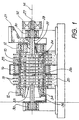
- the mill shown in Fig. 1 has a cylindrical outer drum 10 mounted on bearings 12 for rotation about its central axis 14, driven by means of drum drive pulley 16 attached to its outer surface.
- the drum outer surface also carries cooling fins 18 which pass through a cooling water trough 20 below the drum.
- a feed of flowable particulate material for example a slurry or powder, is introduced to one end of the drum from a feed hopper 21 via feed inlet 22 and is flung outwards to form a layer 23 against the inner surface of the drum.
- the drum is rotated sufficiently above critical speed that the entire mill charge, and any grinding media, travels right around in contact with the drum rather than the sub-critical tumbling operation of prior art mills.
- the drum is preferably rotated at least three times critical speed, most preferably at least ten times, so that the mill charge layer is at high pressure, compressed by the high centrifugal force.
- the magnitude of the compressive forces applied can be varied by varying the speed of rotation of the outer drum.
- the charge layer is mobilised by disc or finger projections 24 of the counterrotating shear inducing member 26 inside the drum, mounted on a central shaft 28 supported in bearings 30. This shaft is rotated by means of a shaft drive pulley 32.
- a cooling water passage 26 extends through shaft 28.
- the shaft is rotated rapidly in the opposite direction to drum 10.
- the shaft may be rotated in the same direction as the drum but at a differential speed. This latter arrangement eliminates a 'dead' locus within the charge layer at which the rotational "G" force is zero, and reduces energy requirements of the mill.
- the particles in the charge layer are subjected to intense interparticle and/or particle to media shear stresses generated by the stirring action of the projections 24 rotating through the compressed charge layer.
- the high pressure due to rotation of the charge layer enhances energy transfer from the projections to the charge, thus transferring a relatively large proportion of the available input energy directly to the particles as fracture promoting stress.
- the shearing of the compressed solids layer causes both shearing and abrasion fracture of the particles, with sufficient energy to cause localised stressing and fracture applied simultaneously to a large proportion of the total particle population within the mill.
- the net result is a high distribution of very fine particles, with the capacity to sustain effective fracture by this mechanism at high particle population expansion rates within the mill.
- particles may also fracture due to compressive force of the media and sold particle bulk pressure, due to the exaggerated "gravitational" force within the mill.
- the magnitude of this compressive force and the particle/particle and particle/media packing densities may be varied. It is believed that some fracture by shatter and attritioning of particle surfaces resulting from higher velocity impacts also occurs, but to a lesser degree than abrasion fracture.
- the discharge end 33 of the mill drum 10 has an annular retaining plate 34 extending radially inwards from the drum inner surface.
- the greater centrifugal force acting on the heavy media particles causes the media to be retained within the mill radially outwards of the retaining plate 34 and therefore kept within the mill while the fine product is displaced by the incoming feed and passes radially inwards of the retaining plate and into a discharge launder 36.
- Figs. 3 and 4 illustrate a vertical mill constructed in accordance with a second embodiment, including non-rotating shear members.
- the rotating drum 40 of the mill is mounted on a vertical rotational axis 42, supported on frame 44 by bearings 46, and is rotated at high speed via the drum drive pulley 48.
- the mill is charged initially with a mix of grinding media, fed from media hopper 50 via ball valve 52, and a feed powder or slurry fed through feed port 54.
- the charge passes down stationary feed tube 55 into the drum.
- Feed impellers 56 attached to the rotating drum impart rotary motion to the charge, which forms a highly compressed layer retained against the drum inner surface.
- the shear inducing member inside the drum is stationary, consisting of one or more radial discs 58 attached to a fixed shaft 60.
- the discs have apertures 62 in the region of the inner free surface 63 of the charge layer to allow axial movement of fine ground material through the mill to the discharge end. If fingers or other projections are used instead of discs 58, the apertures 62 are not required.
- feed port 54 Alter the initial charge is introduced, no further grinding media is added but a continuous stream of feed is fed via feed port 54.
- the mill is adapted to receive feed slurries of high solids content, for example 50-90% solids, typically 55-75%, depending on the feed material and the size reduction required.
- the grinding media and larger particles in the charge layer will tend not to move axially through the mill due the high compressive forces on the charge. Instead radial migration of particles occurs, wherein larger particles introduced in the feed slurry migrate radially outwards through the charge due to the high centrifugal force and are subject to grinding and fracturing by the efficient mechanisms discussed above with reference to Fig. 1. As the particle size reduces, the smaller particles migrate radially inwards until they reach the inner free surface of the charge layer, which equates to a zero (gauge) pressure locus.
- the fine particles reaching the free surface may then move axially through the mill, through apertures 62 in the discs, pass radially inwards of the discharge ring 64 and into discharge launder 66.
- a scraper blade 68 may be affixed to stationary shaft 60 to keep the material flowing freely through the discharge ring.
- zones in the charge away from the shearing discs 58 pack solid and rotate at one with the rotating drum.
- This can be used to advantage by spacing the shearing discs apart by a sufficient distance to create solid ⁇ dead' zones of charge between successive discs and adjacent the end faces of the rotating drum.
- These dead zones 70 shown by the darker shading in Fig. 3, effectively act as solid discs extending inwards from the inner wall of the drum, parallel to and rotating at high speed relative to the discs. This creates an extremely high shear rate in the stirred charge regions 72 (shown in lighter shading in Fig. 3) adjacent the discs, while protecting the end surfaces of the drum against excessive wear.
- the minimum disc spacing required to create this stirred zone/dead zone phenomenon will vary dependent on the rotational speed and charge material used, but in cases of extremely high G force and high solids content may be as little as 50mm.
- the embodiment of Figs. 2 and 3 has the advantage of lower power requirement as it is not necessary to drive the shear-inducing member.
- the power requirement of the mill may be further reduced by reducing the length of the grinding chamber and employing only a single shearing disc.
Landscapes
- Engineering & Computer Science (AREA)
- Food Science & Technology (AREA)
- Crushing And Grinding (AREA)
- Disintegrating Or Milling (AREA)
- Polishing Bodies And Polishing Tools (AREA)
- Processing Of Solid Wastes (AREA)
- Crushing And Pulverization Processes (AREA)
- Food-Manufacturing Devices (AREA)
Claims (18)
- Procédé de broyage d'un matériau particulaire, comprenant l'amenée du matériau particulaire vers un conteneur (10, 40) comprenant une surface intérieure, la rotation du conteneur à une vitesse suffisamment élevée pour que le matériau particulaire forme une couche (23) maintenue contre la surface intérieure tout au long d'une telle rotation, et la mise en contact de la couche avec des moyens entraînant un cisaillement (26, 24, 58) pour entraîner un cisaillement dans ladite couche, caractérisé en ce que l'on effectue une rotation du conteneur (10, 40) à une vitesse suffisante pour qu'au moins une zone sensiblement solidifiée soit présente dans ladite couche de matériau particulaire de façon à ce que ladite zone coopère avec les moyens entraînant un cisaillement (26, 24, 58) afin d'améliorer le cisaillement ainsi entraîné dans ladite couche (23).
- Procédé selon la revendication 1, dans lequel le conteneur est tourné à une vitesse suffisante pour appliquer une force d'au moins cent fois la gravité à la couche de matériau particulaire.
- Procédé selon la revendication 2, dans lequel les moyens de cisaillement créent une ou plusieurs zones agitées (72) dans la couche de matériau particulaire, lesdites zones agitées étant situées entre les moyens de cisaillement et les zones solidifiées.
- Procédé selon la revendication 3, dans lequel une pluralité de moyens de cisaillement sont espacés axialement le long dudit conteneur afin de créer des zones en alternance solidifiées et agitées.
- Procédé selon la revendication 3 ou 4, dans lequel les moyens de cisaillement comprennent des éléments radiaux (24, 58) s'étendant dans la couche de matériau particulaire pour créer lesdites une ou plusieurs zones agitées.
- Procédé selon l'une quelconque des revendications 1 à 5, dans lequel lesdits moyens de cisaillement ne sont pas rotatifs.
- Broyeur pour matériau particulaire, comprenant un conteneur rotatif (10, 40) comprenant une surface intérieure, des moyens d'amenée (21, 22, 55) pour amener le matériau particulaire vers le conteneur, des moyens (16, 48) pour faire tourner le conteneur à une vitesse suffisamment élevée telle que le matériau particulaire forme une couche (23) maintenue contre la surface intérieure tout au long d'une telle rotation, et des moyens entraînant un cisaillement (26, 24, 58) entrant en contact avec ladite couche afin d'entraîner un cisaillement dans ladite couche, lesdits moyens de cisaillement comprenant un ou plusieurs éléments radiaux (24, 58) s'étendant dans la couche de matériau particulaire, caractérisé en ce que lesdits moyens de cisaillement sont montés fixés contre la rotation.
- Broyeur selon la revendication 7, dans lequel les moyens (16, 48) faisant tourner le conteneur sont adaptés pour faire tourner le conteneur à au moins dix fois la vitesse minimum à laquelle le matériau particulaire forme une couche maintenue contre la surface intérieure du conteneur tout au long de sa rotation.
- Broyeur selon la revendication 8, dans lequel les moyens (16, 48) faisant tourner le conteneur sont adaptés pour faire tourner le conteneur à une vitesse suffisante pour appliquer une force d'au moins cent fois la gravité à la couche de matériau particulaire.
- Broyeur selon l'une quelconque des revendications 7 à 9, dans lequel les moyens (16, 48) faisant tourner le conteneur sont adaptés pour faire tourner le conteneur à une vitesse suffisante pour entraîner une ou plusieurs zones sensiblement solidifiées (70) dans la couche de matériau particulaire.
- Broyeur selon la revendication 10, dans lequel les moyens de cisaillement (26, 24, 58) sont agencés pour créer une ou plusieurs zones agitées (72) dans la couche de matériau particulaire, lesdites zones agitées étant situées entre les moyens de cisaillement et les zones solidifiées.
- Broyeur selon la revendication 11, comprenant une pluralité de moyens de cisaillement (24, 58) espacés axialement le long dudit conteneur afin de créer des zones en alternance solidifiées et agitées.
- Procédé de broyage d'un matériau particulaire, comprenant l'amenée du matériau particulaire vers un conteneur (10, 40) qui comprend une surface intérieure, la rotation du conteneur à une vitesse suffisamment élevée telle que le matériau particulaire forme une couche (23) maintenue contre la surface intérieure tout au long d'une telle rotation, et la mise en contact de la couche avec des moyens entraînant un cisaillement (26, 24, 58) pour entraîner un cisaillement dans ladite couche, dans lequel lesdits moyens de cisaillement comprennent un ou plusieurs éléments radiaux (24, 58) s'étendant dans la couche de matériau particulaire, caractérisé en ce que lesdits moyens de cisaillement sont montés fixés contre la rotation.
- Procédé selon la revendication 13, dans lequel le conteneur est tourné à au moins dix fois la vitesse minimum à laquelle le matériau particulaire forme une couche maintenue contre la surface intérieure du conteneur tout au long de sa rotation.
- Procédé selon la revendication 14, dans lequel le conteneur est tourné à une vitesse suffisante pour appliquer une force d'au moins cent fois la gravité à la couche de matériau particulaire.
- Procédé selon l'une quelconque des revendications 13 à 15, dans lequel le conteneur est tourné à une vitesse suffisante pour entraîner une ou plusieurs zones sensiblement solidifiées (70) dans la couche de matériau particulaire.
- Procédé selon la revendication 16, dans lequel les moyens de cisaillement créent une ou plusieurs zones agitées (72) dans la couche de matériau particulaire, lesdites zones agitées étant situées entre les moyens de cisaillement et les zones solidifiées.
- Procédé selon la revendication 17, dans lequel une pluralité de moyens de cisaillement (24, 58) sont espacés axialement le long dudit conteneur afin de créer des zones en alternance solidifiées et agitées.
Applications Claiming Priority (5)
| Application Number | Priority Date | Filing Date | Title |
|---|---|---|---|
| AUPO8835A AUPO883597A0 (en) | 1997-08-29 | 1997-08-29 | Grinding mill |
| AUPO883597 | 1997-08-29 | ||
| AUPP3025A AUPP302598A0 (en) | 1998-04-09 | 1998-04-09 | Grinding mill |
| AUPP302598 | 1998-04-09 | ||
| PCT/AU1998/000692 WO1999011377A1 (fr) | 1997-08-29 | 1998-08-28 | Broyeur |
Publications (3)
| Publication Number | Publication Date |
|---|---|
| EP1017500A1 EP1017500A1 (fr) | 2000-07-12 |
| EP1017500A4 EP1017500A4 (fr) | 2000-12-06 |
| EP1017500B1 true EP1017500B1 (fr) | 2006-03-01 |
Family
ID=25645590
Family Applications (1)
| Application Number | Title | Priority Date | Filing Date |
|---|---|---|---|
| EP98939437A Expired - Lifetime EP1017500B1 (fr) | 1997-08-29 | 1998-08-28 | Broyeur |
Country Status (19)
| Country | Link |
|---|---|
| US (2) | US6375101B1 (fr) |
| EP (1) | EP1017500B1 (fr) |
| JP (1) | JP4409759B2 (fr) |
| CN (1) | CN1131113C (fr) |
| AR (1) | AR013455A1 (fr) |
| AT (1) | ATE318654T1 (fr) |
| BR (1) | BR9812279A (fr) |
| CA (1) | CA2302489C (fr) |
| CZ (1) | CZ294705B6 (fr) |
| DE (1) | DE69833661T2 (fr) |
| EA (1) | EA001279B1 (fr) |
| ES (1) | ES2263215T3 (fr) |
| ID (1) | ID23685A (fr) |
| IL (1) | IL134476A0 (fr) |
| NO (1) | NO20001016D0 (fr) |
| NZ (1) | NZ502898A (fr) |
| PL (1) | PL192081B1 (fr) |
| TR (1) | TR200000548T2 (fr) |
| WO (1) | WO1999011377A1 (fr) |
Families Citing this family (13)
| Publication number | Priority date | Publication date | Assignee | Title |
|---|---|---|---|---|
| DE19912594B4 (de) * | 1999-03-20 | 2008-01-31 | Zoz Gmbh | Vorrichtung zur Hochenergie- und/oder Feinstmahlung von Feststoffen |
| US6450428B1 (en) | 1999-05-05 | 2002-09-17 | Lowan (Management) Pty Limited | Feed arrangement for grinding mill incorporating fluid feed |
| DE10011348A1 (de) * | 2000-03-10 | 2001-11-08 | Siemens Axiva Gmbh & Co Kg | Verfahren zum Mahlen von Kunststoffen |
| DE112005001320B4 (de) * | 2004-06-23 | 2013-03-21 | Masataka Tamura | Brechvorrichtung |
| KR100796267B1 (ko) * | 2007-06-12 | 2008-01-21 | 이태종 | 칡 파쇄기 |
| AU2008295440B2 (en) * | 2007-09-06 | 2011-06-16 | Lowan (Management) Pty Limited | Grinding mill and method of grinding |
| IT1399691B1 (it) * | 2010-03-30 | 2013-04-26 | Soremartec Sa | Metodo per la preparazione di un semilavorato dolciario, ad esempio tipo cioccolato o similare |
| IT1399692B1 (it) * | 2010-03-30 | 2013-04-26 | Soremartec Sa | Metodo e impianto per la preparazione di un prodotto granulato |
| US9446361B2 (en) | 2011-10-11 | 2016-09-20 | Modern Process Equipment, Inc. | Method of densifying coffee |
| DE102013103013A1 (de) * | 2013-03-25 | 2014-09-25 | Maschinenfabrik Gustav Eirich Gmbh & Co. Kg | Verfahren zur Erzeugung eines optimierten Granulats |
| AU2014295806B2 (en) * | 2013-07-22 | 2016-05-19 | Imp Technologies Pty Ltd | Adjustable super fine crusher |
| DE202016104557U1 (de) * | 2016-08-19 | 2016-08-29 | Eduard Biernatek | Mühle, insbesondere Kaffeemühle |
| CN113427674B (zh) * | 2021-08-26 | 2021-11-16 | 南通裕荣电子商务有限公司 | 一种光缆废料的破碎回收设备 |
Family Cites Families (9)
| Publication number | Priority date | Publication date | Assignee | Title |
|---|---|---|---|---|
| US3056561A (en) * | 1958-12-13 | 1962-10-02 | Insinooritormisto Engineering | Method and apparatus for grinding material to a fine degree |
| FR1289073A (fr) * | 1961-05-04 | 1962-03-30 | Kloeckner Humboldt Deutz Ag | Broyeur pour le concassage fin de matières naturelles ou synthétiques |
| SU1045926A1 (ru) * | 1982-06-15 | 1983-10-07 | Свердловский Ордена Трудового Красного Знамени Горный Институт Им.В.В.Вахрушева | Мельница |
| DE3437866A1 (de) | 1984-10-16 | 1986-04-17 | Basf Farben + Fasern Ag, 2000 Hamburg | Dispergierverfahren und ruehrwerksmuehle zu seiner durchfuehrung |
| US5158239A (en) | 1984-10-16 | 1992-10-27 | Basf Lacke & Farben Ag | Dispersing process and stirred ball mill for carrying out this process |
| FR2631253B1 (fr) * | 1988-05-16 | 1994-04-08 | Vernijura Sa | Procede de broyage et dispersion d'un produit ou d'un melange et installation pour la mise en oeuvre du procede |
| DE4128074C2 (de) * | 1991-08-23 | 1995-06-29 | Omya Gmbh | Rührwerkskugelmühle |
| DE19614295A1 (de) * | 1995-04-21 | 1996-10-24 | Friedrich Dr Ing Vock | Verfahren und Vorrichtung zum Nassmahlen und Dispergieren von Feststoffpartikeln in Flüssigkeiten |
| US6450428B1 (en) * | 1999-05-05 | 2002-09-17 | Lowan (Management) Pty Limited | Feed arrangement for grinding mill incorporating fluid feed |
-
1998
- 1998-08-28 CN CN98808267A patent/CN1131113C/zh not_active Expired - Fee Related
- 1998-08-28 PL PL338797A patent/PL192081B1/pl not_active IP Right Cessation
- 1998-08-28 AR ARP980104320A patent/AR013455A1/es unknown
- 1998-08-28 AT AT98939437T patent/ATE318654T1/de not_active IP Right Cessation
- 1998-08-28 IL IL13447698A patent/IL134476A0/xx unknown
- 1998-08-28 US US09/486,374 patent/US6375101B1/en not_active Expired - Lifetime
- 1998-08-28 EA EA200000271A patent/EA001279B1/ru not_active IP Right Cessation
- 1998-08-28 CA CA002302489A patent/CA2302489C/fr not_active Expired - Fee Related
- 1998-08-28 ID IDW20000592A patent/ID23685A/id unknown
- 1998-08-28 WO PCT/AU1998/000692 patent/WO1999011377A1/fr not_active Ceased
- 1998-08-28 BR BR9812279-7A patent/BR9812279A/pt not_active IP Right Cessation
- 1998-08-28 NZ NZ502898A patent/NZ502898A/xx unknown
- 1998-08-28 ES ES98939437T patent/ES2263215T3/es not_active Expired - Lifetime
- 1998-08-28 DE DE69833661T patent/DE69833661T2/de not_active Expired - Lifetime
- 1998-08-28 CZ CZ2000561A patent/CZ294705B6/cs not_active IP Right Cessation
- 1998-08-28 JP JP2000508468A patent/JP4409759B2/ja not_active Expired - Fee Related
- 1998-08-28 EP EP98939437A patent/EP1017500B1/fr not_active Expired - Lifetime
- 1998-08-28 TR TR2000/00548T patent/TR200000548T2/xx unknown
-
2000
- 2000-02-29 NO NO20001016A patent/NO20001016D0/no not_active Application Discontinuation
-
2002
- 2002-03-15 US US10/097,299 patent/US6764034B2/en not_active Expired - Fee Related
Also Published As
| Publication number | Publication date |
|---|---|
| CN1131113C (zh) | 2003-12-17 |
| WO1999011377A1 (fr) | 1999-03-11 |
| CA2302489C (fr) | 2008-01-22 |
| JP4409759B2 (ja) | 2010-02-03 |
| EA200000271A1 (ru) | 2000-08-28 |
| ATE318654T1 (de) | 2006-03-15 |
| EA001279B1 (ru) | 2000-12-25 |
| US20020088882A1 (en) | 2002-07-11 |
| CZ2000561A3 (cs) | 2000-11-15 |
| PL192081B1 (pl) | 2006-08-31 |
| EP1017500A4 (fr) | 2000-12-06 |
| ID23685A (id) | 2000-05-11 |
| CZ294705B6 (cs) | 2005-02-16 |
| TR200000548T2 (tr) | 2000-08-21 |
| EP1017500A1 (fr) | 2000-07-12 |
| US6375101B1 (en) | 2002-04-23 |
| NO20001016L (no) | 2000-02-29 |
| NZ502898A (en) | 2000-12-22 |
| ES2263215T3 (es) | 2006-12-01 |
| US6764034B2 (en) | 2004-07-20 |
| AR013455A1 (es) | 2000-12-27 |
| PL338797A1 (en) | 2000-11-20 |
| CN1267239A (zh) | 2000-09-20 |
| DE69833661D1 (de) | 2006-04-27 |
| CA2302489A1 (fr) | 1999-03-11 |
| NO20001016D0 (no) | 2000-02-29 |
| DE69833661T2 (de) | 2006-12-28 |
| BR9812279A (pt) | 2000-07-18 |
| IL134476A0 (en) | 2001-04-30 |
| JP2001514072A (ja) | 2001-09-11 |
Similar Documents
| Publication | Publication Date | Title |
|---|---|---|
| EP1017500B1 (fr) | Broyeur | |
| CN110177623B (zh) | 用于处理高湿度进料的行星辊磨机 | |
| US11396022B2 (en) | Mono roller grinding mill | |
| JPS6287257A (ja) | 環状ギヤツプ型ボ−ルミル | |
| JPH0228377B2 (fr) | ||
| AU732830B2 (en) | Grinding mill | |
| JP2597179B2 (ja) | 遠心流動粉砕装置 | |
| MXPA00001918A (en) | Grinding mill | |
| RU2105608C1 (ru) | Центробежная мельница | |
| JPH0234660B2 (ja) | Enshinryudofunsaisochi | |
| RU2343980C1 (ru) | Способ измельчения сыпучих материалов | |
| JP2594829B2 (ja) | 遠心流動粉砕装置 | |
| WO2022016286A1 (fr) | Système et procédé de broyage de matériau | |
| JPH02100871A (ja) | 遠心流動装置の運転方法 | |
| EA044401B1 (ru) | Одновалковая мельница | |
| JPH0365252A (ja) | 遠心流動粉砕装置 | |
| JPH0679674B2 (ja) | 遠心流動粉砕装置 | |
| JPH0232024B2 (ja) | Enshinryudofunsaisochi | |
| JPH0751586A (ja) | 竪型粉砕機 | |
| JPS62125869A (ja) | 遠心流動粉砕装置 | |
| JPH05337387A (ja) | 遠心流動粉砕装置 | |
| AU3023600A (en) | Feed arrangement for grinding mill incorporating fluid feed | |
| JPH0234659B2 (ja) | Enshinryudofunsaisochi |
Legal Events
| Date | Code | Title | Description |
|---|---|---|---|
| PUAI | Public reference made under article 153(3) epc to a published international application that has entered the european phase |
Free format text: ORIGINAL CODE: 0009012 |
|
| 17P | Request for examination filed |
Effective date: 20000225 |
|
| AK | Designated contracting states |
Kind code of ref document: A1 Designated state(s): AT BE CH CY DE DK ES FI FR GB GR IE IT LI LU MC NL PT SE |
|
| A4 | Supplementary search report drawn up and despatched |
Effective date: 20001026 |
|
| AK | Designated contracting states |
Kind code of ref document: A4 Designated state(s): AT BE CH CY DE DK ES FI FR GB GR IE IT LI LU MC NL PT SE |
|
| 17Q | First examination report despatched |
Effective date: 20011011 |
|
| GRAP | Despatch of communication of intention to grant a patent |
Free format text: ORIGINAL CODE: EPIDOSNIGR1 |
|
| GRAS | Grant fee paid |
Free format text: ORIGINAL CODE: EPIDOSNIGR3 |
|
| GRAL | Information related to payment of fee for publishing/printing deleted |
Free format text: ORIGINAL CODE: EPIDOSDIGR3 |
|
| GRAP | Despatch of communication of intention to grant a patent |
Free format text: ORIGINAL CODE: EPIDOSNIGR1 |
|
| GRAS | Grant fee paid |
Free format text: ORIGINAL CODE: EPIDOSNIGR3 |
|
| GRAA | (expected) grant |
Free format text: ORIGINAL CODE: 0009210 |
|
| RAP1 | Party data changed (applicant data changed or rights of an application transferred) |
Owner name: EDI RAIL PTY LTD |
|
| AK | Designated contracting states |
Kind code of ref document: B1 Designated state(s): AT BE CH CY DE DK ES FI FR GB GR IE IT LI LU MC NL PT SE |
|
| PG25 | Lapsed in a contracting state [announced via postgrant information from national office to epo] |
Ref country code: NL Free format text: LAPSE BECAUSE OF FAILURE TO SUBMIT A TRANSLATION OF THE DESCRIPTION OR TO PAY THE FEE WITHIN THE PRESCRIBED TIME-LIMIT Effective date: 20060301 Ref country code: LI Free format text: LAPSE BECAUSE OF FAILURE TO SUBMIT A TRANSLATION OF THE DESCRIPTION OR TO PAY THE FEE WITHIN THE PRESCRIBED TIME-LIMIT Effective date: 20060301 Ref country code: CH Free format text: LAPSE BECAUSE OF FAILURE TO SUBMIT A TRANSLATION OF THE DESCRIPTION OR TO PAY THE FEE WITHIN THE PRESCRIBED TIME-LIMIT Effective date: 20060301 Ref country code: BE Free format text: LAPSE BECAUSE OF FAILURE TO SUBMIT A TRANSLATION OF THE DESCRIPTION OR TO PAY THE FEE WITHIN THE PRESCRIBED TIME-LIMIT Effective date: 20060301 Ref country code: AT Free format text: LAPSE BECAUSE OF FAILURE TO SUBMIT A TRANSLATION OF THE DESCRIPTION OR TO PAY THE FEE WITHIN THE PRESCRIBED TIME-LIMIT Effective date: 20060301 |
|
| REG | Reference to a national code |
Ref country code: GB Ref legal event code: FG4D |
|
| REG | Reference to a national code |
Ref country code: CH Ref legal event code: EP |
|
| REG | Reference to a national code |
Ref country code: IE Ref legal event code: FG4D |
|
| REF | Corresponds to: |
Ref document number: 69833661 Country of ref document: DE Date of ref document: 20060427 Kind code of ref document: P |
|
| PG25 | Lapsed in a contracting state [announced via postgrant information from national office to epo] |
Ref country code: DK Free format text: LAPSE BECAUSE OF FAILURE TO SUBMIT A TRANSLATION OF THE DESCRIPTION OR TO PAY THE FEE WITHIN THE PRESCRIBED TIME-LIMIT Effective date: 20060601 |
|
| REG | Reference to a national code |
Ref country code: SE Ref legal event code: TRGR |
|
| PG25 | Lapsed in a contracting state [announced via postgrant information from national office to epo] |
Ref country code: PT Free format text: LAPSE BECAUSE OF FAILURE TO SUBMIT A TRANSLATION OF THE DESCRIPTION OR TO PAY THE FEE WITHIN THE PRESCRIBED TIME-LIMIT Effective date: 20060801 |
|
| PG25 | Lapsed in a contracting state [announced via postgrant information from national office to epo] |
Ref country code: IE Free format text: LAPSE BECAUSE OF NON-PAYMENT OF DUE FEES Effective date: 20060828 |
|
| PG25 | Lapsed in a contracting state [announced via postgrant information from national office to epo] |
Ref country code: MC Free format text: LAPSE BECAUSE OF NON-PAYMENT OF DUE FEES Effective date: 20060831 |
|
| NLV1 | Nl: lapsed or annulled due to failure to fulfill the requirements of art. 29p and 29m of the patents act | ||
| REG | Reference to a national code |
Ref country code: CH Ref legal event code: PL |
|
| ET | Fr: translation filed | ||
| REG | Reference to a national code |
Ref country code: ES Ref legal event code: FG2A Ref document number: 2263215 Country of ref document: ES Kind code of ref document: T3 |
|
| PLBE | No opposition filed within time limit |
Free format text: ORIGINAL CODE: 0009261 |
|
| STAA | Information on the status of an ep patent application or granted ep patent |
Free format text: STATUS: NO OPPOSITION FILED WITHIN TIME LIMIT |
|
| 26N | No opposition filed |
Effective date: 20061204 |
|
| PG25 | Lapsed in a contracting state [announced via postgrant information from national office to epo] |
Ref country code: GR Free format text: LAPSE BECAUSE OF FAILURE TO SUBMIT A TRANSLATION OF THE DESCRIPTION OR TO PAY THE FEE WITHIN THE PRESCRIBED TIME-LIMIT Effective date: 20060602 |
|
| PG25 | Lapsed in a contracting state [announced via postgrant information from national office to epo] |
Ref country code: LU Free format text: LAPSE BECAUSE OF NON-PAYMENT OF DUE FEES Effective date: 20060828 |
|
| PG25 | Lapsed in a contracting state [announced via postgrant information from national office to epo] |
Ref country code: CY Free format text: LAPSE BECAUSE OF FAILURE TO SUBMIT A TRANSLATION OF THE DESCRIPTION OR TO PAY THE FEE WITHIN THE PRESCRIBED TIME-LIMIT Effective date: 20060301 |
|
| PGFP | Annual fee paid to national office [announced via postgrant information from national office to epo] |
Ref country code: SE Payment date: 20110824 Year of fee payment: 14 Ref country code: GB Payment date: 20110715 Year of fee payment: 14 |
|
| PGFP | Annual fee paid to national office [announced via postgrant information from national office to epo] |
Ref country code: IT Payment date: 20110725 Year of fee payment: 14 |
|
| REG | Reference to a national code |
Ref country code: SE Ref legal event code: EUG |
|
| GBPC | Gb: european patent ceased through non-payment of renewal fee |
Effective date: 20120828 |
|
| PG25 | Lapsed in a contracting state [announced via postgrant information from national office to epo] |
Ref country code: SE Free format text: LAPSE BECAUSE OF NON-PAYMENT OF DUE FEES Effective date: 20120829 |
|
| PG25 | Lapsed in a contracting state [announced via postgrant information from national office to epo] |
Ref country code: IT Free format text: LAPSE BECAUSE OF NON-PAYMENT OF DUE FEES Effective date: 20120828 |
|
| PG25 | Lapsed in a contracting state [announced via postgrant information from national office to epo] |
Ref country code: GB Free format text: LAPSE BECAUSE OF NON-PAYMENT OF DUE FEES Effective date: 20120828 |
|
| PGFP | Annual fee paid to national office [announced via postgrant information from national office to epo] |
Ref country code: FI Payment date: 20130819 Year of fee payment: 16 Ref country code: ES Payment date: 20130726 Year of fee payment: 16 |
|
| PGFP | Annual fee paid to national office [announced via postgrant information from national office to epo] |
Ref country code: FR Payment date: 20130828 Year of fee payment: 16 |
|
| PGFP | Annual fee paid to national office [announced via postgrant information from national office to epo] |
Ref country code: DE Payment date: 20131031 Year of fee payment: 16 |
|
| REG | Reference to a national code |
Ref country code: DE Ref legal event code: R119 Ref document number: 69833661 Country of ref document: DE |
|
| PG25 | Lapsed in a contracting state [announced via postgrant information from national office to epo] |
Ref country code: FI Free format text: LAPSE BECAUSE OF NON-PAYMENT OF DUE FEES Effective date: 20140828 |
|
| REG | Reference to a national code |
Ref country code: FR Ref legal event code: ST Effective date: 20150430 |
|
| REG | Reference to a national code |
Ref country code: DE Ref legal event code: R119 Ref document number: 69833661 Country of ref document: DE Effective date: 20150303 |
|
| PG25 | Lapsed in a contracting state [announced via postgrant information from national office to epo] |
Ref country code: DE Free format text: LAPSE BECAUSE OF NON-PAYMENT OF DUE FEES Effective date: 20150303 |
|
| PG25 | Lapsed in a contracting state [announced via postgrant information from national office to epo] |
Ref country code: FR Free format text: LAPSE BECAUSE OF NON-PAYMENT OF DUE FEES Effective date: 20140901 |
|
| REG | Reference to a national code |
Ref country code: ES Ref legal event code: FD2A Effective date: 20150925 |
|
| PG25 | Lapsed in a contracting state [announced via postgrant information from national office to epo] |
Ref country code: ES Free format text: LAPSE BECAUSE OF NON-PAYMENT OF DUE FEES Effective date: 20140829 |