EP1017525B1 - Schneideinsatzhalter und schlüssel für schneideinsatzhalter - Google Patents
Schneideinsatzhalter und schlüssel für schneideinsatzhalter Download PDFInfo
- Publication number
- EP1017525B1 EP1017525B1 EP98939849A EP98939849A EP1017525B1 EP 1017525 B1 EP1017525 B1 EP 1017525B1 EP 98939849 A EP98939849 A EP 98939849A EP 98939849 A EP98939849 A EP 98939849A EP 1017525 B1 EP1017525 B1 EP 1017525B1
- Authority
- EP
- European Patent Office
- Prior art keywords
- seat
- key
- projection
- shaft
- stud
- Prior art date
- Legal status (The legal status is an assumption and is not a legal conclusion. Google has not performed a legal analysis and makes no representation as to the accuracy of the status listed.)
- Expired - Lifetime
Links
- 238000005452 bending Methods 0.000 claims description 6
- 230000000694 effects Effects 0.000 claims description 2
- 238000004519 manufacturing process Methods 0.000 description 2
- 230000001464 adherent effect Effects 0.000 description 1
- 230000001419 dependent effect Effects 0.000 description 1
- 238000006073 displacement reaction Methods 0.000 description 1
- 239000011800 void material Substances 0.000 description 1
Images


Classifications
-
- B—PERFORMING OPERATIONS; TRANSPORTING
- B23—MACHINE TOOLS; METAL-WORKING NOT OTHERWISE PROVIDED FOR
- B23B—TURNING; BORING
- B23B27/00—Tools for turning or boring machines; Tools of a similar kind in general; Accessories therefor
- B23B27/04—Cutting-off tools
-
- B—PERFORMING OPERATIONS; TRANSPORTING
- B23—MACHINE TOOLS; METAL-WORKING NOT OTHERWISE PROVIDED FOR
- B23B—TURNING; BORING
- B23B2205/00—Fixation of cutting inserts in holders
- B23B2205/02—Fixation using an elastically deformable clamping member
-
- B—PERFORMING OPERATIONS; TRANSPORTING
- B23—MACHINE TOOLS; METAL-WORKING NOT OTHERWISE PROVIDED FOR
- B23B—TURNING; BORING
- B23B2260/00—Details of constructional elements
- B23B2260/078—Hand tools used to operate chucks or to assemble, adjust or disassemble tools or equipment used for turning, boring or drilling
- B23B2260/0785—Hand tools used to operate chucks or to assemble, adjust or disassemble tools or equipment used for turning, boring or drilling for unclamping cutting inserts
-
- Y—GENERAL TAGGING OF NEW TECHNOLOGICAL DEVELOPMENTS; GENERAL TAGGING OF CROSS-SECTIONAL TECHNOLOGIES SPANNING OVER SEVERAL SECTIONS OF THE IPC; TECHNICAL SUBJECTS COVERED BY FORMER USPC CROSS-REFERENCE ART COLLECTIONS [XRACs] AND DIGESTS
- Y10—TECHNICAL SUBJECTS COVERED BY FORMER USPC
- Y10T—TECHNICAL SUBJECTS COVERED BY FORMER US CLASSIFICATION
- Y10T407/00—Cutters, for shaping
- Y10T407/22—Cutters, for shaping including holder having seat for inserted tool
- Y10T407/2272—Cutters, for shaping including holder having seat for inserted tool with separate means to fasten tool to holder
- Y10T407/2282—Cutters, for shaping including holder having seat for inserted tool with separate means to fasten tool to holder including tool holding clamp and clamp actuator
-
- Y—GENERAL TAGGING OF NEW TECHNOLOGICAL DEVELOPMENTS; GENERAL TAGGING OF CROSS-SECTIONAL TECHNOLOGIES SPANNING OVER SEVERAL SECTIONS OF THE IPC; TECHNICAL SUBJECTS COVERED BY FORMER USPC CROSS-REFERENCE ART COLLECTIONS [XRACs] AND DIGESTS
- Y10—TECHNICAL SUBJECTS COVERED BY FORMER USPC
- Y10T—TECHNICAL SUBJECTS COVERED BY FORMER US CLASSIFICATION
- Y10T407/00—Cutters, for shaping
- Y10T407/22—Cutters, for shaping including holder having seat for inserted tool
- Y10T407/2272—Cutters, for shaping including holder having seat for inserted tool with separate means to fasten tool to holder
- Y10T407/2282—Cutters, for shaping including holder having seat for inserted tool with separate means to fasten tool to holder including tool holding clamp and clamp actuator
- Y10T407/2286—Resiliently biased clamp jaw
-
- Y—GENERAL TAGGING OF NEW TECHNOLOGICAL DEVELOPMENTS; GENERAL TAGGING OF CROSS-SECTIONAL TECHNOLOGIES SPANNING OVER SEVERAL SECTIONS OF THE IPC; TECHNICAL SUBJECTS COVERED BY FORMER USPC CROSS-REFERENCE ART COLLECTIONS [XRACs] AND DIGESTS
- Y10—TECHNICAL SUBJECTS COVERED BY FORMER USPC
- Y10T—TECHNICAL SUBJECTS COVERED BY FORMER US CLASSIFICATION
- Y10T407/00—Cutters, for shaping
- Y10T407/22—Cutters, for shaping including holder having seat for inserted tool
- Y10T407/2272—Cutters, for shaping including holder having seat for inserted tool with separate means to fasten tool to holder
- Y10T407/2282—Cutters, for shaping including holder having seat for inserted tool with separate means to fasten tool to holder including tool holding clamp and clamp actuator
- Y10T407/2286—Resiliently biased clamp jaw
- Y10T407/2288—Integral with holder
Definitions
- this invention relates to an insert holder of the type comprising a blade-shaped body having a slot adapted to receive a cutting insert, said slot being defined by an elastically flexible arm arranged to resiliently clamp the cutting insert in the slot, two seats, which open laterally, being provided in said insert holder one in the clamping arm (4) and the other located in the body (1), said seats to receive two spaced-apart projections of a key, said projections having the function of bending the clamping arm outwards and widening the slot in connection with the mounting or dismounting of the cutting insert, more precisely by turning the key around a fulcrum defined by one of the seats and a projection of the key engaging said seat at the same time as the other projection engages the other seat.
- the invention also relates to a key for such insert holders.
- Insert holders and keys of the type generally defined above are previously known in two different embodiments in EP 0 654 316.
- an insert holder is shown having one of its seats recessed in the flexible clamping arm while the other seat is recessed in the body itself, more precisely in a point below the slot intended for the cutting insert.
- two types of keys are suggested, the first one being shown in figure 3 and having the shape of a plate with two separated legs upon which projections in the shape of studs are provided, and between said projections there is a wedge body that by the aid of a screw mechanism may increase or decrease the distance between the legs and consequently the distance between said studs.
- the presence of a screw mechanism also constitutes a latent risk for functional incompetence, e.g. by damaging or fouling of the threads of the mechanism.
- a key of the type generally defined above is previously known from US 4,588,333 wherein the key comprises a shaft having two axially, spaced-apart projections but this key is designed to operate directly against a rear surface of a cutting insert forcing it out of the supporting slot.
- a serious disadvantage with this solution is that the repeated mounting and dismounting of the cutting insert causes rapid wear of the contact surfaces of the slot which in turn means a tool holder incapable of providing adequate clamping and positioning of the insert.
- the clamping arm returns to its starting position as soon as the key is released.
- Another disadvantage is that a large manual force is required to bend the clamping arm outwards since the distance between the studs is small.
- a serious disadvantage is also that the bending outwards of the clamping arm takes place in an uncontrolled way. If the operator applies an excessive force upon the clamping arm, said arm may be plastically deformed and thus unusable.
- a primary object of the invention is to create an insert holder and a key in combination with each other guarantee a predictable deflection or bending of the clamping arm while using a reasonable manual force simultaneously as the key should be structurally simple and cheap to manufacture.
- a further object is to create an insert holder and a key which makes it possible to automatically maintain the key in a condition where the clamping arm is kept deflected, i.e. without applying a manual force to the key.
- FIGS. 4 and 5 illustrating an insert holder having the shape of or comprising a blade-shaped body 1, an outwardly opening slot or recess 2 being provided in said body 1, said slot or recess 2 being adapted to receive a cutting insert 3.
- the slot 2 is defined by, on one hand, a lower and forward portion of the body 1, and on the other hand, by an elastically flexible arm 4 having the function of clamping the cutting insert 3 in the slot 2.
- an abutment surface 5 against which the cutting insert abuts when mounted.
- two different seats 6, 7 are provided, which may either be designed as through holes or as recesses having a limited depth and opening only at one side of the body.
- One of the seats 6 is cylindrical and in the disclosed embodiment located in the clamping arm 4.
- the other seat 7 is located in the area below the slot 5, said other seat 7, in accordance with the present invention, having an oblong shape.
- the seat 7 is arched in shape and extends between opposite ends designated by 8, 8', which are located at different distances from the seat 6. More specifically, the seat or the notch is limited by a lower arc-shaped surface 9 that at the end 8' is converted into a shallow recess 10.
- the notch 7 is located in such a way that the radial distance from the bottom of said recess 10 is somewhat smaller than the radial distance between the seat 6 and the bottom surface 9 at the end 8.
- the difference in distance or radius indicated by the designation S in figure 4, may in practice constitute fractions of a millimetre.
- the difference in distance S may be within the interval 0,2 - 1,0 mm, preferably 0,3 - 0,7 mm.
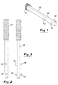
- FIG. 1 illustrating two alternative embodiments of a lever key according to the invention.
- said key comprises a handle member 11 and a shaft 12 having at least a pair of axially spaced projections 13, 14.
- the shaft in the first case, has a rectangular cross-section, i.e. the shaft is flat, while the shaft according to figures 2 and 3 is cylindrical.
- the first projection 13 on the shaft 12 has the shape of a cylindrical stud whose diameter is only a little smaller than the diameter of the cylindrical seat 6. This means that the stud 13 projects at a right angle from the shaft 12.
- the cross-section of the stud may be oval or elliptic, more precisely in such a way that the major axis of the ellipse is oriented perpendicular to the longitudinal axis of the shaft.
- the distance between the two studs 13 and 14 should on one hand be larger than 1/10 of the entire length of the shaft and on the other hand smaller than 1/3 of the entire length of the shaft. Per se both the length of the shaft as well as the distance between the studs may vary depending on which type of insert holder that is to be treated. However, the length of the shaft should be in the range of 100-200 mm and the distance between the studs may be within the range of 20-60 mm.
- opposite pairs of projections are provided on the shaft 12.
- an oval stud 14' At the side of the shaft that is opposite to the cylindrical stud 13 there is an oval stud 14' and in an analogous way there is a cylindrical stud 13' at the side of the shaft that is opposite to the oval stud 14.
- FIG 5 is shown how the key is attached to the insert holder 1, more precisely with the cylindrical stud 13' mounted in the cylindrical seat 6 and the oval stud 14' engaging the arc-shaped notch 7.
- the key is oriented downwards from the insert holder.
- said key may be oriented in such a way that the stud 13 at the opposite side of the shaft engages the cylindrical seat 6 and the oval stud 14 engages the notch 7. From the starting position shown in figure 5 the key shaft is brought to turn counter-clockwise around the fulcrum defined by the seat 6 and the stud 13'.
- the projection 14' is moved from one end 8 of the notch 7 to the opposite end 8', whereby the stud glides along the bottom surface 9. Due to the fact that the notch is so oriented relative to the seat 6 that the radial distance to the seat 6 is shortened successively in direction towards the end 8', the elastically flexible clamping arm 4 will successively bend outwards far enough to allow the insert 3 to be removed from the slot 2.
- the stud 14' reaches the end position at the end 8' of the notch it will be positioned in the recess 10, this arrangement guaranteeing that the key is automatically maintained in its inner end position. In other words the operator does not need to apply any force upon the key to keep the clamping arm 4 bent outwards.
- the radial distance between the seat 6 and the recess 10 is somewhat larger than the corresponding distance from the bottom surface 7 in the absolute vicinity of the recess. Nevertheless the radial distance between the recess and the seat 6 is obviously smaller than the corresponding radial distance at the opposite end 8 of the notch.
- FIG 6 an alternative embodiment of the insert holder is shown, the oblong seat or notch 7 in its bottom surface having a central bowl-like shoulder surface 10' located at a radial distance from the seat 6, said distance being at least somewhat smaller than the corresponding radial distance at the opposite ends of the notch.
- the key may thus be turned inwards from either one of the two opposite ends of the notch and effect bending outwards of the clamping arm when the stud reaches the shoulder surface 10'.
- figures 7 and 8 are shown examples of straight notches, the notch according to figure 7 including a recess at one end thereof, while the notch according to figure 8 is void of a special, position-maintaining recess.
- the geometric shape of the oblong seat may be varied in many ways.
- said seat generally has an oblong shape and that the radial distance between on one hand the fulcrum defined by a cylindrical seat and a first projection and on the other hand the surface of the seat abutting the second projection is shortened when the second projection is displaced along a running surface of the seat.
Landscapes
- Engineering & Computer Science (AREA)
- Mechanical Engineering (AREA)
- Clamps And Clips (AREA)
- Supports Or Holders For Household Use (AREA)
- Surgical Instruments (AREA)
- Cutting Tools, Boring Holders, And Turrets (AREA)
Claims (6)
- Einsatzhalter mit einem blattförmigen Körper (1) mit einem Schlitz (2) zur Aufnahme eines Schneideinsatzes (3), wobei dieser Schlitz (2) durch einen elastisch flexiblen Arm (4) begrenzt ist, der so angeordnet ist, daß er den Schneideinsatz in dem Schlitz elastisch festklemmt, zwei Sitzen (6, 7), die seitlich offen sind und einer in dem Einsatzhalter in dem Klemmarm (4) und der andere in dem Körper (1) vorgesehen ist, wobei diese Sitze so angeordnet sind, daß sie zwei voneinander beabstandete Vorsprünge (13, 14; 13', 14') eines Schlüssels aufnehmen und wobei die Vorsprünge die Funktion haben, den Klemmarm nach außen zu biegen und den Schlitz in Verbindung mit dem Befestigen oder Lösen des Schneidaufsatzes aufweiten, genauer durch Drehen des Schlüssels um einen Drehpunkt, der durch einen der Sitze (6) definiert ist, und ein Vorsprung (13, 13') des Schlüssels in den Sitz (6) eingreift, während gleichzeitig der andere Vorsprung (14, 14') in den anderen Sitz (7) eingreift, dadurch gekennzeichnet, daß dieser andere Sitz (7) eine längliche Form hat, um ein Auswärtsbiegen des Klemmarms (4) durch Verschieben des anderen Vorsprungs (14, 14') des Schlüssels von einem Punkt in einem bestimmten Abstand von dem ersten Sitz (6) zu einem anderen Punkt in einem kürzeren Abstand von dem ersten Sitz (6) zu bewirken.
- Einsatzhalter nach Anspruch 1, dadurch gekennzeichnet, daß der längliche Sitz (7) eine Vertiefung (10) an einem Punkt in einem kürzeren Abstand von dem ersten Sitz (6) hat, wobei der andere Vorsprung (14, 14') in dieser Vertiefung (10) gehalten wird, wenn der Schaft (12) des Schlüssels zu einer aktiven Stellung gedreht wird, wo der Klemmarm nach außen gebogen wird.
- Einsatzhalter nach Anspruch 1 oder 2, dadurch gekennzeichnet, daß der längliche Sitz (7) in dem Körper (1) eingelassen ist, während der den Drehpunkt definierende Sitz (6) in dem Klemmarm (4) eingelassen ist.
- Einsatzhalter nach einem der vorausgehenden Ansprüche, dadurch gekennzeichnet, daß der längliche Sitz (7) seine beiden entgegengesetzten Enden in unterschiedlichen Abständen von dem Sitz hat, der als Drehpunkt dient.
- Schlüssel zur Verwendung, um einen Schneideinsatz in einem Schlitz in einem Einsatzhalter der Art befestigen und/oder daraus lösen zu können, der einen blattförmigen Körper (1) einschließt, der Schlüssel einen Schaft (12) mit zwei axial voneinander beabstandeten Vorsprüngen (13, 14; 13', 14') hat, ein erster Vorsprung (13', 14) nahe einem freien Ende des Schaftes angeordnet ist und ein zweiter Vorsprung (13, 14') axial von dem ersten Vorsprung beabstandet ist und der Abstand zwischen den Vorsprüngen größer als 1/10 und kleiner als 1/3 der Gesamtlänge des Schaftes ist, dadurch gekennzeichnet, daß der Vorsprung (13, 13'), der dazu bestimmt ist, als der Drehpunkt zu wirken, die Form eines zylindrischen Ansatzes hat, während der andere Vorsprung (14, 14') die Form eines Ansatzes mit einem ovalen Querschnitt hat.
- Schlüssel nach Anspruch 5, dadurch gekennzeichnet, daß entgegengesetzte Paare von Vorsprüngen an dem Schaft vorgesehen sind, nämlich an einer Seite ein Paar in der Form eines zylindrischen Ansatzes (13') am nächsten dem freien Ende des Schaftes und eines ovalen Ansatzes (14') in einem Abstand von dem zylindrischen Ansatz (13') und an der anderen Seite ein Paar in der Form eines ovalen Ansatzes (14) am nächsten dem freien Ende des Schaftes und eines zylindrischen Ansatzes (13) in einem Abstand von dem ovalen Ansatz (14).
Applications Claiming Priority (3)
| Application Number | Priority Date | Filing Date | Title |
|---|---|---|---|
| SE9703433 | 1997-09-24 | ||
| SE9703433A SE512592C2 (sv) | 1997-09-24 | 1997-09-24 | Skärhållare jämte nyckel för skärhållare |
| PCT/SE1998/001508 WO1999015296A1 (en) | 1997-09-24 | 1998-08-24 | Insert holder and key for insert holders |
Publications (2)
| Publication Number | Publication Date |
|---|---|
| EP1017525A1 EP1017525A1 (de) | 2000-07-12 |
| EP1017525B1 true EP1017525B1 (de) | 2002-11-27 |
Family
ID=20408344
Family Applications (1)
| Application Number | Title | Priority Date | Filing Date |
|---|---|---|---|
| EP98939849A Expired - Lifetime EP1017525B1 (de) | 1997-09-24 | 1998-08-24 | Schneideinsatzhalter und schlüssel für schneideinsatzhalter |
Country Status (4)
| Country | Link |
|---|---|
| EP (1) | EP1017525B1 (de) |
| JP (1) | JP2001517555A (de) |
| DE (1) | DE69809780T2 (de) |
| SE (1) | SE512592C2 (de) |
Families Citing this family (3)
| Publication number | Priority date | Publication date | Assignee | Title |
|---|---|---|---|---|
| US8647029B2 (en) * | 2012-01-03 | 2014-02-11 | Iscar, Ltd. | Cutting tool and method for extracting cutting insert therefrom |
| US9120239B2 (en) * | 2013-02-21 | 2015-09-01 | Iscar, Ltd. | Cutting tool and cutting insert having insert key recesses for extracting and mounting therein |
| KR102393688B1 (ko) * | 2016-09-06 | 2022-05-04 | 이스카 엘티디. | 분리용 인서트 어댑터 |
Citations (1)
| Publication number | Priority date | Publication date | Assignee | Title |
|---|---|---|---|---|
| US4588333A (en) * | 1984-02-20 | 1986-05-13 | Seco Tools Ab | Chip cutting tool |
-
1997
- 1997-09-24 SE SE9703433A patent/SE512592C2/sv not_active IP Right Cessation
-
1998
- 1998-08-24 JP JP2000512652A patent/JP2001517555A/ja active Pending
- 1998-08-24 DE DE69809780T patent/DE69809780T2/de not_active Expired - Fee Related
- 1998-08-24 EP EP98939849A patent/EP1017525B1/de not_active Expired - Lifetime
Patent Citations (1)
| Publication number | Priority date | Publication date | Assignee | Title |
|---|---|---|---|---|
| US4588333A (en) * | 1984-02-20 | 1986-05-13 | Seco Tools Ab | Chip cutting tool |
Also Published As
| Publication number | Publication date |
|---|---|
| SE9703433D0 (sv) | 1997-09-24 |
| SE9703433L (sv) | 1999-03-25 |
| JP2001517555A (ja) | 2001-10-09 |
| DE69809780D1 (de) | 2003-01-09 |
| DE69809780T2 (de) | 2003-07-17 |
| SE512592C2 (sv) | 2000-04-10 |
| EP1017525A1 (de) | 2000-07-12 |
Similar Documents
| Publication | Publication Date | Title |
|---|---|---|
| KR100626926B1 (ko) | 절삭 인서트 클램핑 기구 | |
| KR101330482B1 (ko) | 인서트 탈착식 공구 | |
| US7780380B2 (en) | Insert-indexable tool | |
| US5987758A (en) | Quick-change blade clamp | |
| JP4176862B2 (ja) | 切削加工差込み工具用クランプ装置 | |
| RU2149080C1 (ru) | Пластина отрезная или канавочная | |
| WO1999015296A1 (en) | Insert holder and key for insert holders | |
| US5516241A (en) | Holder blade | |
| JPH0392206A (ja) | スローアウエイチップのクランプ機構 | |
| KR950008006A (ko) | 절삭 공구 | |
| JPH10506851A (ja) | ドリル刃先部を有するドリル | |
| EP1328366A1 (de) | Drehendes werkzeug mit ersetzbarem schneidteil | |
| KR19990006862A (ko) | 축방향으로 조절 가능한 밀링 공구 | |
| KR20000048383A (ko) | 절삭 공구 조립체 | |
| KR950701716A (ko) | 셀프보오링 고정구(self-boring fastener) | |
| EP1314503A1 (de) | Werkzeug zur spanabhebenden Bearbeitung | |
| US6814526B2 (en) | Insert holder for parting and grooving operations | |
| EP1017525B1 (de) | Schneideinsatzhalter und schlüssel für schneideinsatzhalter | |
| JPH032604B2 (de) | ||
| KR20010023806A (ko) | 칩제거 가공용 공구 | |
| JPH11320248A (ja) | 切り屑を除去する機械加工用工具 | |
| EP0027491A1 (de) | Nutloser Halter für Loch-Wendeplatten | |
| KR100694270B1 (ko) | 손상된 나사선을 수리하기 위한 공구 | |
| EP0582633B1 (de) | Werkzeug für die bearbeitung schwerzugänglichen räumen, beispielsweise für innendrehen | |
| EP1007254B2 (de) | Schlüssel für blattförmige schneideinsatzhalter |
Legal Events
| Date | Code | Title | Description |
|---|---|---|---|
| PUAI | Public reference made under article 153(3) epc to a published international application that has entered the european phase |
Free format text: ORIGINAL CODE: 0009012 |
|
| 17P | Request for examination filed |
Effective date: 20000315 |
|
| AK | Designated contracting states |
Kind code of ref document: A1 Designated state(s): DE FR GB IT SE |
|
| 17Q | First examination report despatched |
Effective date: 20011023 |
|
| GRAG | Despatch of communication of intention to grant |
Free format text: ORIGINAL CODE: EPIDOS AGRA |
|
| GRAG | Despatch of communication of intention to grant |
Free format text: ORIGINAL CODE: EPIDOS AGRA |
|
| GRAH | Despatch of communication of intention to grant a patent |
Free format text: ORIGINAL CODE: EPIDOS IGRA |
|
| GRAH | Despatch of communication of intention to grant a patent |
Free format text: ORIGINAL CODE: EPIDOS IGRA |
|
| GRAA | (expected) grant |
Free format text: ORIGINAL CODE: 0009210 |
|
| AK | Designated contracting states |
Kind code of ref document: B1 Designated state(s): DE FR GB IT SE |
|
| PG25 | Lapsed in a contracting state [announced via postgrant information from national office to epo] |
Ref country code: IT Free format text: LAPSE BECAUSE OF FAILURE TO SUBMIT A TRANSLATION OF THE DESCRIPTION OR TO PAY THE FEE WITHIN THE PRE;WARNING: LAPSES OF ITALIAN PATENTS WITH EFFECTIVE DATE BEFORE 2007 MAY HAVE OCCURRED AT ANY TIME BEFORE 2007. THE CORRECT EFFECTIVE DATE MAY BE DIFFERENT FROM THE ONE RECORDED.SCRIBED TIME-LIMIT Effective date: 20021127 |
|
| REG | Reference to a national code |
Ref country code: GB Ref legal event code: FG4D |
|
| REF | Corresponds to: |
Ref document number: 69809780 Country of ref document: DE Date of ref document: 20030109 |
|
| PG25 | Lapsed in a contracting state [announced via postgrant information from national office to epo] |
Ref country code: SE Free format text: LAPSE BECAUSE OF FAILURE TO SUBMIT A TRANSLATION OF THE DESCRIPTION OR TO PAY THE FEE WITHIN THE PRESCRIBED TIME-LIMIT Effective date: 20030227 |
|
| ET | Fr: translation filed | ||
| PGFP | Annual fee paid to national office [announced via postgrant information from national office to epo] |
Ref country code: FR Payment date: 20030808 Year of fee payment: 6 |
|
| PGFP | Annual fee paid to national office [announced via postgrant information from national office to epo] |
Ref country code: GB Payment date: 20030820 Year of fee payment: 6 |
|
| PGFP | Annual fee paid to national office [announced via postgrant information from national office to epo] |
Ref country code: DE Payment date: 20030904 Year of fee payment: 6 |
|
| PLBE | No opposition filed within time limit |
Free format text: ORIGINAL CODE: 0009261 |
|
| STAA | Information on the status of an ep patent application or granted ep patent |
Free format text: STATUS: NO OPPOSITION FILED WITHIN TIME LIMIT |
|
| 26N | No opposition filed |
Effective date: 20030828 |
|
| PG25 | Lapsed in a contracting state [announced via postgrant information from national office to epo] |
Ref country code: GB Free format text: LAPSE BECAUSE OF NON-PAYMENT OF DUE FEES Effective date: 20040824 |
|
| PG25 | Lapsed in a contracting state [announced via postgrant information from national office to epo] |
Ref country code: DE Free format text: LAPSE BECAUSE OF NON-PAYMENT OF DUE FEES Effective date: 20050301 |
|
| GBPC | Gb: european patent ceased through non-payment of renewal fee |
Effective date: 20040824 |
|
| PG25 | Lapsed in a contracting state [announced via postgrant information from national office to epo] |
Ref country code: FR Free format text: LAPSE BECAUSE OF NON-PAYMENT OF DUE FEES Effective date: 20050429 |
|
| REG | Reference to a national code |
Ref country code: FR Ref legal event code: ST |