EP1017562B1 - Matiere a bouclettes, son procede de fabrication et son utilisation dans des produits - Google Patents
Matiere a bouclettes, son procede de fabrication et son utilisation dans des produits Download PDFInfo
- Publication number
- EP1017562B1 EP1017562B1 EP19980950607 EP98950607A EP1017562B1 EP 1017562 B1 EP1017562 B1 EP 1017562B1 EP 19980950607 EP19980950607 EP 19980950607 EP 98950607 A EP98950607 A EP 98950607A EP 1017562 B1 EP1017562 B1 EP 1017562B1
- Authority
- EP
- European Patent Office
- Prior art keywords
- web
- loops
- fibers
- loop
- loop fastener
- Prior art date
- Legal status (The legal status is an assumption and is not a legal conclusion. Google has not performed a legal analysis and makes no representation as to the accuracy of the status listed.)
- Expired - Lifetime
Links
- 239000000463 material Substances 0.000 title claims description 90
- 238000004519 manufacturing process Methods 0.000 title description 11
- 239000000835 fiber Substances 0.000 claims abstract description 225
- 239000011230 binding agent Substances 0.000 claims abstract description 70
- 238000000034 method Methods 0.000 claims abstract description 67
- 239000004744 fabric Substances 0.000 claims description 47
- 239000012530 fluid Substances 0.000 claims description 19
- 230000015572 biosynthetic process Effects 0.000 claims description 13
- 238000005755 formation reaction Methods 0.000 claims description 13
- 230000004888 barrier function Effects 0.000 claims description 12
- 239000002689 soil Substances 0.000 claims description 10
- 239000012815 thermoplastic material Substances 0.000 claims description 10
- 230000001154 acute effect Effects 0.000 claims description 9
- 230000000087 stabilizing effect Effects 0.000 claims description 9
- 239000003673 groundwater Substances 0.000 claims description 8
- 229920001169 thermoplastic Polymers 0.000 claims description 8
- 239000004416 thermosoftening plastic Substances 0.000 claims description 8
- 238000001914 filtration Methods 0.000 claims description 7
- 239000004746 geotextile Substances 0.000 claims description 7
- 238000009828 non-uniform distribution Methods 0.000 claims description 6
- 229920006397 acrylic thermoplastic Polymers 0.000 claims description 4
- 239000012141 concentrate Substances 0.000 claims description 4
- 229920003229 poly(methyl methacrylate) Polymers 0.000 claims description 4
- ISXSCDLOGDJUNJ-UHFFFAOYSA-N tert-butyl prop-2-enoate Chemical compound CC(C)(C)OC(=O)C=C ISXSCDLOGDJUNJ-UHFFFAOYSA-N 0.000 claims description 4
- 239000004593 Epoxy Substances 0.000 claims description 3
- WSFSSNUMVMOOMR-UHFFFAOYSA-N Formaldehyde Chemical class O=C WSFSSNUMVMOOMR-UHFFFAOYSA-N 0.000 claims description 3
- 125000003700 epoxy group Chemical group 0.000 claims description 3
- 235000019256 formaldehyde Nutrition 0.000 claims description 3
- 229920000647 polyepoxide Polymers 0.000 claims description 3
- 229920000642 polymer Polymers 0.000 claims description 3
- 238000007711 solidification Methods 0.000 claims description 3
- 230000008023 solidification Effects 0.000 claims description 3
- 150000003673 urethanes Chemical class 0.000 claims description 3
- 229920002554 vinyl polymer Polymers 0.000 claims description 3
- 238000005728 strengthening Methods 0.000 claims description 2
- 239000000047 product Substances 0.000 abstract description 135
- 238000004080 punching Methods 0.000 abstract description 11
- 229920005822 acrylic binder Polymers 0.000 abstract description 4
- 239000007795 chemical reaction product Substances 0.000 abstract 1
- 230000008569 process Effects 0.000 description 19
- 239000000853 adhesive Substances 0.000 description 18
- 230000001070 adhesive effect Effects 0.000 description 18
- 241000239290 Araneae Species 0.000 description 14
- 238000000576 coating method Methods 0.000 description 10
- 238000009960 carding Methods 0.000 description 9
- 239000007788 liquid Substances 0.000 description 9
- 229920003023 plastic Polymers 0.000 description 8
- 239000004033 plastic Substances 0.000 description 8
- -1 polypropylene Polymers 0.000 description 8
- 239000004575 stone Substances 0.000 description 8
- 239000011248 coating agent Substances 0.000 description 7
- 230000035515 penetration Effects 0.000 description 7
- XLYOFNOQVPJJNP-UHFFFAOYSA-N water Substances O XLYOFNOQVPJJNP-UHFFFAOYSA-N 0.000 description 7
- 239000004698 Polyethylene Substances 0.000 description 6
- 230000008901 benefit Effects 0.000 description 6
- 239000006260 foam Substances 0.000 description 6
- 239000012467 final product Substances 0.000 description 5
- 229920000728 polyester Polymers 0.000 description 5
- 229920000573 polyethylene Polymers 0.000 description 5
- 239000000758 substrate Substances 0.000 description 5
- 230000000739 chaotic effect Effects 0.000 description 4
- 230000006870 function Effects 0.000 description 4
- 239000004745 nonwoven fabric Substances 0.000 description 4
- 238000003466 welding Methods 0.000 description 4
- 230000009471 action Effects 0.000 description 3
- 230000008859 change Effects 0.000 description 3
- 230000013011 mating Effects 0.000 description 3
- 239000004677 Nylon Substances 0.000 description 2
- 239000004743 Polypropylene Substances 0.000 description 2
- 239000004820 Pressure-sensitive adhesive Substances 0.000 description 2
- 230000035508 accumulation Effects 0.000 description 2
- 238000009825 accumulation Methods 0.000 description 2
- NIXOWILDQLNWCW-UHFFFAOYSA-N acrylic acid group Chemical group C(C=C)(=O)O NIXOWILDQLNWCW-UHFFFAOYSA-N 0.000 description 2
- 239000000956 alloy Substances 0.000 description 2
- 229910045601 alloy Inorganic materials 0.000 description 2
- 238000004873 anchoring Methods 0.000 description 2
- 238000012512 characterization method Methods 0.000 description 2
- 239000000470 constituent Substances 0.000 description 2
- 238000010276 construction Methods 0.000 description 2
- 229920001577 copolymer Polymers 0.000 description 2
- 229920006240 drawn fiber Polymers 0.000 description 2
- 239000000839 emulsion Substances 0.000 description 2
- 238000009950 felting Methods 0.000 description 2
- 238000010438 heat treatment Methods 0.000 description 2
- 238000003475 lamination Methods 0.000 description 2
- 239000000203 mixture Substances 0.000 description 2
- 229920001778 nylon Polymers 0.000 description 2
- 239000002420 orchard Substances 0.000 description 2
- 230000000149 penetrating effect Effects 0.000 description 2
- 229920001155 polypropylene Polymers 0.000 description 2
- 238000013022 venting Methods 0.000 description 2
- NIXOWILDQLNWCW-UHFFFAOYSA-M Acrylate Chemical compound [O-]C(=O)C=C NIXOWILDQLNWCW-UHFFFAOYSA-M 0.000 description 1
- 235000001674 Agaricus brunnescens Nutrition 0.000 description 1
- 239000004484 Briquette Substances 0.000 description 1
- 229920000742 Cotton Polymers 0.000 description 1
- JOYRKODLDBILNP-UHFFFAOYSA-N Ethyl urethane Chemical compound CCOC(N)=O JOYRKODLDBILNP-UHFFFAOYSA-N 0.000 description 1
- 229910001111 Fine metal Inorganic materials 0.000 description 1
- 239000004952 Polyamide Substances 0.000 description 1
- 206010040880 Skin irritation Diseases 0.000 description 1
- 229920002472 Starch Polymers 0.000 description 1
- 230000004308 accommodation Effects 0.000 description 1
- 230000003213 activating effect Effects 0.000 description 1
- 230000004913 activation Effects 0.000 description 1
- 230000002411 adverse Effects 0.000 description 1
- RREGISFBPQOLTM-UHFFFAOYSA-N alumane;trihydrate Chemical compound O.O.O.[AlH3] RREGISFBPQOLTM-UHFFFAOYSA-N 0.000 description 1
- 230000003466 anti-cipated effect Effects 0.000 description 1
- 229910000410 antimony oxide Inorganic materials 0.000 description 1
- 238000005452 bending Methods 0.000 description 1
- 230000009286 beneficial effect Effects 0.000 description 1
- 230000036772 blood pressure Effects 0.000 description 1
- 238000007664 blowing Methods 0.000 description 1
- 239000003610 charcoal Substances 0.000 description 1
- 238000001816 cooling Methods 0.000 description 1
- 239000006071 cream Substances 0.000 description 1
- 238000004132 cross linking Methods 0.000 description 1
- WHHGLZMJPXIBIX-UHFFFAOYSA-N decabromodiphenyl ether Chemical compound BrC1=C(Br)C(Br)=C(Br)C(Br)=C1OC1=C(Br)C(Br)=C(Br)C(Br)=C1Br WHHGLZMJPXIBIX-UHFFFAOYSA-N 0.000 description 1
- 230000007423 decrease Effects 0.000 description 1
- 238000006073 displacement reaction Methods 0.000 description 1
- 238000009826 distribution Methods 0.000 description 1
- 238000001035 drying Methods 0.000 description 1
- 230000005489 elastic deformation Effects 0.000 description 1
- 239000013536 elastomeric material Substances 0.000 description 1
- 238000011067 equilibration Methods 0.000 description 1
- 238000002474 experimental method Methods 0.000 description 1
- 238000001125 extrusion Methods 0.000 description 1
- 239000002657 fibrous material Substances 0.000 description 1
- 239000003063 flame retardant Substances 0.000 description 1
- 238000005187 foaming Methods 0.000 description 1
- 235000013305 food Nutrition 0.000 description 1
- ZZUFCTLCJUWOSV-UHFFFAOYSA-N furosemide Chemical compound C1=C(Cl)C(S(=O)(=O)N)=CC(C(O)=O)=C1NCC1=CC=CO1 ZZUFCTLCJUWOSV-UHFFFAOYSA-N 0.000 description 1
- 229920001519 homopolymer Polymers 0.000 description 1
- 239000012943 hotmelt Substances 0.000 description 1
- 230000006872 improvement Effects 0.000 description 1
- 230000007794 irritation Effects 0.000 description 1
- 238000005304 joining Methods 0.000 description 1
- 238000011068 loading method Methods 0.000 description 1
- 230000007246 mechanism Effects 0.000 description 1
- 239000000155 melt Substances 0.000 description 1
- 229910052751 metal Inorganic materials 0.000 description 1
- 239000002184 metal Substances 0.000 description 1
- 230000000116 mitigating effect Effects 0.000 description 1
- 238000002156 mixing Methods 0.000 description 1
- VTRUBDSFZJNXHI-UHFFFAOYSA-N oxoantimony Chemical compound [Sb]=O VTRUBDSFZJNXHI-UHFFFAOYSA-N 0.000 description 1
- 238000004806 packaging method and process Methods 0.000 description 1
- 239000012466 permeate Substances 0.000 description 1
- 229920002647 polyamide Polymers 0.000 description 1
- 229920000139 polyethylene terephthalate Polymers 0.000 description 1
- 239000005020 polyethylene terephthalate Substances 0.000 description 1
- 229920000098 polyolefin Polymers 0.000 description 1
- 229920002635 polyurethane Polymers 0.000 description 1
- 239000004814 polyurethane Substances 0.000 description 1
- 229920002689 polyvinyl acetate Polymers 0.000 description 1
- 239000011118 polyvinyl acetate Substances 0.000 description 1
- 239000011148 porous material Substances 0.000 description 1
- 238000002360 preparation method Methods 0.000 description 1
- 238000003825 pressing Methods 0.000 description 1
- 229920005989 resin Polymers 0.000 description 1
- 239000011347 resin Substances 0.000 description 1
- 230000000717 retained effect Effects 0.000 description 1
- 239000004576 sand Substances 0.000 description 1
- 230000037307 sensitive skin Effects 0.000 description 1
- 238000009958 sewing Methods 0.000 description 1
- 239000008257 shaving cream Substances 0.000 description 1
- 230000036556 skin irritation Effects 0.000 description 1
- 231100000475 skin irritation Toxicity 0.000 description 1
- 239000002904 solvent Substances 0.000 description 1
- 230000006641 stabilisation Effects 0.000 description 1
- 238000011105 stabilization Methods 0.000 description 1
- 235000019698 starch Nutrition 0.000 description 1
- 239000008107 starch Substances 0.000 description 1
- 239000007858 starting material Substances 0.000 description 1
- 239000003351 stiffener Substances 0.000 description 1
- BIKXLKXABVUSMH-UHFFFAOYSA-N trizinc;diborate Chemical compound [Zn+2].[Zn+2].[Zn+2].[O-]B([O-])[O-].[O-]B([O-])[O-] BIKXLKXABVUSMH-UHFFFAOYSA-N 0.000 description 1
- 235000013311 vegetables Nutrition 0.000 description 1
- 238000009736 wetting Methods 0.000 description 1
- 210000002268 wool Anatomy 0.000 description 1
- 230000037303 wrinkles Effects 0.000 description 1
Images




Classifications
-
- A—HUMAN NECESSITIES
- A44—HABERDASHERY; JEWELLERY
- A44B—BUTTONS, PINS, BUCKLES, SLIDE FASTENERS, OR THE LIKE
- A44B18/00—Fasteners of the touch-and-close type; Making such fasteners
- A44B18/0003—Fastener constructions
- A44B18/0011—Female or loop elements
-
- B—PERFORMING OPERATIONS; TRANSPORTING
- B32—LAYERED PRODUCTS
- B32B—LAYERED PRODUCTS, i.e. PRODUCTS BUILT-UP OF STRATA OF FLAT OR NON-FLAT, e.g. CELLULAR OR HONEYCOMB, FORM
- B32B3/00—Layered products comprising a layer with external or internal discontinuities or unevennesses, or a layer of non-planar shape; Layered products comprising a layer having particular features of form
- B32B3/02—Layered products comprising a layer with external or internal discontinuities or unevennesses, or a layer of non-planar shape; Layered products comprising a layer having particular features of form characterised by features of form at particular places, e.g. in edge regions
- B32B3/06—Layered products comprising a layer with external or internal discontinuities or unevennesses, or a layer of non-planar shape; Layered products comprising a layer having particular features of form characterised by features of form at particular places, e.g. in edge regions for securing layers together; for attaching the product to another member, e.g. to a support, or to another product, e.g. groove/tongue, interlocking
-
- A—HUMAN NECESSITIES
- A61—MEDICAL OR VETERINARY SCIENCE; HYGIENE
- A61F—FILTERS IMPLANTABLE INTO BLOOD VESSELS; PROSTHESES; DEVICES PROVIDING PATENCY TO, OR PREVENTING COLLAPSING OF, TUBULAR STRUCTURES OF THE BODY, e.g. STENTS; ORTHOPAEDIC, NURSING OR CONTRACEPTIVE DEVICES; FOMENTATION; TREATMENT OR PROTECTION OF EYES OR EARS; BANDAGES, DRESSINGS OR ABSORBENT PADS; FIRST-AID KITS
- A61F13/00—Bandages or dressings; Absorbent pads
- A61F13/15—Absorbent pads, e.g. sanitary towels, swabs or tampons for external or internal application to the body; Supporting or fastening means therefor; Tampon applicators
- A61F13/56—Supporting or fastening means
- A61F13/62—Mechanical fastening means ; Fabric strip fastener elements, e.g. hook and loop
- A61F13/622—Fabric strip fastener elements, e.g. hook and loop
- A61F13/627—Fabric strip fastener elements, e.g. hook and loop characterised by the loop
-
- D—TEXTILES; PAPER
- D04—BRAIDING; LACE-MAKING; KNITTING; TRIMMINGS; NON-WOVEN FABRICS
- D04H—MAKING TEXTILE FABRICS, e.g. FROM FIBRES OR FILAMENTARY MATERIAL; FABRICS MADE BY SUCH PROCESSES OR APPARATUS, e.g. FELTS, NON-WOVEN FABRICS; COTTON-WOOL; WADDING ; NON-WOVEN FABRICS FROM STAPLE FIBRES, FILAMENTS OR YARNS, BONDED WITH AT LEAST ONE WEB-LIKE MATERIAL DURING THEIR CONSOLIDATION
- D04H11/00—Non-woven pile fabrics
-
- Y—GENERAL TAGGING OF NEW TECHNOLOGICAL DEVELOPMENTS; GENERAL TAGGING OF CROSS-SECTIONAL TECHNOLOGIES SPANNING OVER SEVERAL SECTIONS OF THE IPC; TECHNICAL SUBJECTS COVERED BY FORMER USPC CROSS-REFERENCE ART COLLECTIONS [XRACs] AND DIGESTS
- Y10—TECHNICAL SUBJECTS COVERED BY FORMER USPC
- Y10T—TECHNICAL SUBJECTS COVERED BY FORMER US CLASSIFICATION
- Y10T24/00—Buckles, buttons, clasps, etc.
- Y10T24/19—Necktie fastener
- Y10T24/1903—Bands
-
- Y—GENERAL TAGGING OF NEW TECHNOLOGICAL DEVELOPMENTS; GENERAL TAGGING OF CROSS-SECTIONAL TECHNOLOGIES SPANNING OVER SEVERAL SECTIONS OF THE IPC; TECHNICAL SUBJECTS COVERED BY FORMER USPC CROSS-REFERENCE ART COLLECTIONS [XRACs] AND DIGESTS
- Y10—TECHNICAL SUBJECTS COVERED BY FORMER USPC
- Y10T—TECHNICAL SUBJECTS COVERED BY FORMER US CLASSIFICATION
- Y10T24/00—Buckles, buttons, clasps, etc.
- Y10T24/27—Buckles, buttons, clasps, etc. including readily dissociable fastener having numerous, protruding, unitary filaments randomly interlocking with, and simultaneously moving towards, mating structure [e.g., hook-loop type fastener]
-
- Y—GENERAL TAGGING OF NEW TECHNOLOGICAL DEVELOPMENTS; GENERAL TAGGING OF CROSS-SECTIONAL TECHNOLOGIES SPANNING OVER SEVERAL SECTIONS OF THE IPC; TECHNICAL SUBJECTS COVERED BY FORMER USPC CROSS-REFERENCE ART COLLECTIONS [XRACs] AND DIGESTS
- Y10—TECHNICAL SUBJECTS COVERED BY FORMER USPC
- Y10T—TECHNICAL SUBJECTS COVERED BY FORMER US CLASSIFICATION
- Y10T428/00—Stock material or miscellaneous articles
- Y10T428/13—Hollow or container type article [e.g., tube, vase, etc.]
-
- Y—GENERAL TAGGING OF NEW TECHNOLOGICAL DEVELOPMENTS; GENERAL TAGGING OF CROSS-SECTIONAL TECHNOLOGIES SPANNING OVER SEVERAL SECTIONS OF THE IPC; TECHNICAL SUBJECTS COVERED BY FORMER USPC CROSS-REFERENCE ART COLLECTIONS [XRACs] AND DIGESTS
- Y10—TECHNICAL SUBJECTS COVERED BY FORMER USPC
- Y10T—TECHNICAL SUBJECTS COVERED BY FORMER US CLASSIFICATION
- Y10T428/00—Stock material or miscellaneous articles
- Y10T428/23907—Pile or nap type surface or component
- Y10T428/23929—Edge feature or configured or discontinuous surface
-
- Y—GENERAL TAGGING OF NEW TECHNOLOGICAL DEVELOPMENTS; GENERAL TAGGING OF CROSS-SECTIONAL TECHNOLOGIES SPANNING OVER SEVERAL SECTIONS OF THE IPC; TECHNICAL SUBJECTS COVERED BY FORMER USPC CROSS-REFERENCE ART COLLECTIONS [XRACs] AND DIGESTS
- Y10—TECHNICAL SUBJECTS COVERED BY FORMER USPC
- Y10T—TECHNICAL SUBJECTS COVERED BY FORMER US CLASSIFICATION
- Y10T428/00—Stock material or miscellaneous articles
- Y10T428/23907—Pile or nap type surface or component
- Y10T428/23929—Edge feature or configured or discontinuous surface
- Y10T428/23936—Differential pile length or surface
-
- Y—GENERAL TAGGING OF NEW TECHNOLOGICAL DEVELOPMENTS; GENERAL TAGGING OF CROSS-SECTIONAL TECHNOLOGIES SPANNING OVER SEVERAL SECTIONS OF THE IPC; TECHNICAL SUBJECTS COVERED BY FORMER USPC CROSS-REFERENCE ART COLLECTIONS [XRACs] AND DIGESTS
- Y10—TECHNICAL SUBJECTS COVERED BY FORMER USPC
- Y10T—TECHNICAL SUBJECTS COVERED BY FORMER US CLASSIFICATION
- Y10T428/00—Stock material or miscellaneous articles
- Y10T428/23907—Pile or nap type surface or component
- Y10T428/23957—Particular shape or structure of pile
-
- Y—GENERAL TAGGING OF NEW TECHNOLOGICAL DEVELOPMENTS; GENERAL TAGGING OF CROSS-SECTIONAL TECHNOLOGIES SPANNING OVER SEVERAL SECTIONS OF THE IPC; TECHNICAL SUBJECTS COVERED BY FORMER USPC CROSS-REFERENCE ART COLLECTIONS [XRACs] AND DIGESTS
- Y10—TECHNICAL SUBJECTS COVERED BY FORMER USPC
- Y10T—TECHNICAL SUBJECTS COVERED BY FORMER US CLASSIFICATION
- Y10T428/00—Stock material or miscellaneous articles
- Y10T428/24—Structurally defined web or sheet [e.g., overall dimension, etc.]
- Y10T428/24008—Structurally defined web or sheet [e.g., overall dimension, etc.] including fastener for attaching to external surface
-
- Y—GENERAL TAGGING OF NEW TECHNOLOGICAL DEVELOPMENTS; GENERAL TAGGING OF CROSS-SECTIONAL TECHNOLOGIES SPANNING OVER SEVERAL SECTIONS OF THE IPC; TECHNICAL SUBJECTS COVERED BY FORMER USPC CROSS-REFERENCE ART COLLECTIONS [XRACs] AND DIGESTS
- Y10—TECHNICAL SUBJECTS COVERED BY FORMER USPC
- Y10T—TECHNICAL SUBJECTS COVERED BY FORMER US CLASSIFICATION
- Y10T428/00—Stock material or miscellaneous articles
- Y10T428/24—Structurally defined web or sheet [e.g., overall dimension, etc.]
- Y10T428/24008—Structurally defined web or sheet [e.g., overall dimension, etc.] including fastener for attaching to external surface
- Y10T428/24017—Hook or barb
-
- Y—GENERAL TAGGING OF NEW TECHNOLOGICAL DEVELOPMENTS; GENERAL TAGGING OF CROSS-SECTIONAL TECHNOLOGIES SPANNING OVER SEVERAL SECTIONS OF THE IPC; TECHNICAL SUBJECTS COVERED BY FORMER USPC CROSS-REFERENCE ART COLLECTIONS [XRACs] AND DIGESTS
- Y10—TECHNICAL SUBJECTS COVERED BY FORMER USPC
- Y10T—TECHNICAL SUBJECTS COVERED BY FORMER US CLASSIFICATION
- Y10T442/00—Fabric [woven, knitted, or nonwoven textile or cloth, etc.]
- Y10T442/20—Coated or impregnated woven, knit, or nonwoven fabric which is not [a] associated with another preformed layer or fiber layer or, [b] with respect to woven and knit, characterized, respectively, by a particular or differential weave or knit, wherein the coating or impregnation is neither a foamed material nor a free metal or alloy layer
- Y10T442/241—Coating or impregnation improves snag or pull resistance of the fabric
Definitions
- This invention relates to loop material, particularly to material to be engaged with hooking members to form a fastening, to its manufacture and use, and to fasteners comprising such loop material.
- woven and non-woven materials In the production of woven and non-woven materials, it is common to form the material as a continuous web that is subsequently spooled.
- woven and knit loop materials loop-forming filaments or yarns are included in the structure of a fabric to form upstanding loops for engaging hooks.
- hook-and-loop fasteners find broader ranges of application, especially in inexpensive, disposable products, some forms of non-woven materials have been suggested to serve as a loop material to reduce the cost and weight of the loop product while providing adequate closure performance in terms of peel and shear strength. Nevertheless, cost of the loop component has remained a major factor limiting the extent of use of hook and loop fasteners.
- non-woven fabrics constructed with certain structural features are capable of functioning well for their intended purpose as hook-engageable loop fabrics, while providing particular advantage in regard to expense of manufacture and other properties.
- a loop fastener component of a hook-and-loop fastener comprising a non-woven web of entangled fibers having a generally planar web body from at least one face of which fibers in the form of hook-engageable loops extend, is characterized in that the web, including the web body and the loops, has weight less than about 4 ounces per square yard (135 grams per square meter), that the web body comprises a non-uniform distribution of fibers in which fibers are in relatively high concentrations in regions of bases of the hook-engageable loops, and in relatively lower concentrations in regions lying between the bases of the loops, and that a substantial number of fibers in regions of lower concentration are taut in the plane of the web body, and extend in different directions radiating from the bases of the loops.
- the bases of the loops contain taut portions of fibers of the web body trained about loop-forming fibers;
- Taut fibers of the bases contribute to the definition of free-standing formations that extend from the plane of the web body and contain the hook-engageable loops;
- the free-standing formations have elongated trunks from each of which multiple hook-engageable loops extend;
- the relatively high concentrations of fibers at the bases of hook-engageable loops define tightened fiber entanglements
- the combined weight of the web body and the loops is less that about 2 ounces per square yard (68 grams per square meter);
- the loops are disposed across the face of the web body in a relatively random pattern.
- a solidified fluid binder is concentrated at the bases of the loops.
- the binder may be selected from the group consisting of acrylics, urethanes, polyvinyls, formaldehydes, glyoxals and epoxies.
- the solidified fluid binder is configured at the bases of the loops at least partially as a result of capillary flow prior to solidification.
- the solidified fluid binder composes between about 20 and 40 percent (preferably, about one third) of the total weight of the web, including the loops.
- the loop fastener component is combined with a layer of thermoplastic material, such that a second face of the web body, opposite the face from which hook-engageable loops extend, is encapsulated in the layer of thermoplastic material.
- hook elements are integrally molded on a surface of the layer of thermoplastic material.
- Thermoplastic fibers of the web are heat-fused at the bases of hook-engageable loops
- the loop fastener component is formed from a needled non-woven starting batt of given dimension, with the web of the loop fastener component, in its general plane of extent, in a stabilized stretched condition of at least 20 percent (preferably, at least 50 percent and more preferably, at least 100 percent) greater area than the area of the starting batt;
- the web is in a stretched condition of at least 20 percent in at least a first direction in the general plane of extent of the web;
- the web is in a stretched condition of at least 20 percent in each of two orthogonal directions in the general plane of extent of the web.
- the starting batt comprises layers of generally parallel fibers with fibers of some layers oriented at acute angles with respect to fibers of other layers, and, as a result of stretching, the acute angles between fibers of the web body corresponding to different layers of the starting batt are generally greater than corresponding angles in the starting batt, while at least many of the fibers corresponding to each layer remain relatively parallel.
- the layers of a longitudinally extending starting batt extend predominantly transversely across the batt, and, as a result of longitudinal stretching of the starting batt, the acute angles between fibers of the web body corresponding to different layers of the starting batt are generally greater than corresponding angles in the starting batt.
- the loop fastener component has an overall thickness, including the web body and a majority of the loops, of less than about 0.150 inch (4.0 mm), preferably less than about 0.100 inch (2.5 mm);
- the hook-engageable loops extend from associated loop bases within the plane of the web to an average loop height, measured as the perpendicular distance from the web body, of between about 0.020 and 0.060 inch (0.5 and 1.0 mm);
- the web has an overall thickness, including the web body and a majority of the loops, the average loop height being between about 0.5 and 0.8 times the overall thickness of the product;
- the loop fastener component has between about 50 and 1000 tightened fiber entanglements per square inch (8 and 160 per square cm) of web area, from which hook-engageable loops extend;
- the web is generally composed of fibers having a tenacity of at least 2.8 grams per denier (preferably, at least 5.0 grams per denier and more preferably at least 8.0 grams per denier);
- the loops extend from the web body to varied heights to form a multi-level arrangement of hook-engageable loops
- the fibers are of a material selected from the group consisting of polyester, polyurethane, polypropylene polyethylene, nylon, homopolymers, mixtures, copolymers, alloys, or co-extrusions thereof and natural fibers;
- the loop fastener component has a Gurley stiffness of less than about 300 milligrams.
- the loop fastener component includes separated strengthening strands extending at least in one direction within the plane of the web body.
- the invention provides an enclosure comprising a first closure portion having loops, and a second closure portion having hooks constructed to engage the loops of the first closure portion to hold the enclosure in an open or closed position, the enclosure being characterized in that the first closure portion comprises the above-described loop fastener product.
- the first and second closure portions have a combined overall thickness, engaged and at rest, of less than about 0.075 inch (1.9 mm).
- a disposable article of clothing has a fabric and a fastener with hooking elements arranged to engage loops of the fabric to form a releasable fastening to retain the article of clothing on a wearer, the article of clothing being characterized in that the fabric comprises the above-described loop fastener component.
- an air filter characterized in that the filter comprises the above-described loop fastener product arranged to intercept and filter a flow of air.
- the barrier comprises the above-described loop fastener product arranged to intercept and filter a flow of groundwater. In another aspect, the barrier comprises the above-described loop fastener product arranged to stabilize a soil layer boundary.
- a fastener product has a sheet-form polymer base with hooks integrally molded with and extending from one side of the base, and a loop material permanently bonded to and extending over an opposite side of the base.
- the loop material of the product comprises the above-described loop fastener material, with the loops of the loop fastener material adapted to be engaged by the hooks of the product.
- the product may be formed, for instance, by use of the techniques described in U.S. Patent 5,518,795 .
- the invention also provides, in combination, a hook fastener product having hooks extending from a surface thereof, and the above-described loop fastener product, the hooks of the hook fastener product being adapted to engage the loops of the loop fastener product to form a releasable fastening.
- the hook fastener product and the loop fastener product have a combined overall thickness, engaged and at rest, of less than about 0.075 inch (1.9 mm), preferably less than about 0.050 inch (1.9 mm).
- hook-engageable and similar terms used above and throughout this specification, we mean that the loop material defines openings of size adequate to receive the tip or head portion of a male fastener element (such as a hook-shape or mushroom-shape element, for instance) for forming a fastening.
- a male fastener element such as a hook-shape or mushroom-shape element, for instance
- entanglements we mean that the nodes at which a multiplicity of fibers are intertwined in the non-woven web. These entanglements may be relatively loose, as formed directly by a needling process, for instance, or tightened after formation of the entanglements.
- nots we mean entanglements that have been tightened by applying tension to their intertwined fibers in at least one direction in the plane of the web, and remain in an at least partially tightened state.
- stabilized we mean that the web is processed to generally maintain its planar dimensions. In other words, a web “stabilized” in a stretched condition will generally maintain its stretched dimensions and not significantly relax or stretch further under conditions of normal use.
- One way of “stabilizing” the web, for instance, is by solidifying binder at a significant proportion of its entanglements.
- loop fabrics as just described are advantageously produced by employing certain manufacturing techniques and methods.
- An important aspect of the invention is a method of forming a loop fastener component for hook-and-loop fastening from a generally planar non-woven batt of entangled fibers.
- the method is characterized by stretching the batt in at least one direction, thereby producing a stretched web of weight less than about 4 ounces per square yard (135 grams per square meter) and having a generally planar web body with a non-uniform distribution of fibers, with fibers in relatively high concentrations in regions of bases of hook-engageable loops extending from the web body, and in relatively lower concentrations in regions of the web between bases of the loops, with a substantial number of fibers in regions of lower concentration being taut in the plane of the web body, and extending in different directions radiating from the bases of the loops; and thereafter stabilizing the web in its stretched condition.
- the stretching causes taut fibers of the web body to be trained about loop-forming fibers in the bases of the loops;
- the batt is stretched in a manner that the fibers of the bases contribute to the definition of free-standing formations that extend from the plane of the web body and contain the hook-engageable loops;
- the batt is stretched in a manner that the formations comprise elongated trunks from each of which multiple hook-engageable loops extend;
- the batt is stretched in a manner that the relatively high concentrations of fibers at the bases of hook-engageable loops define tightened fiber entanglements;
- the batt is stretched so as to produce a web having a weight, including the loops, of less than about 2 ounces per square yard (68 grams per square meter);
- the loops become disposed across the face of the web body in a relatively random pattern as the batt is stretched.
- the web is stabilized in its stretched condition by solidifying a fluid binder, applied to the web body under conditions that concentrate the binder at the bases of the loops.
- the fluid binder may be selected, for instance, from the group consisting of acrylics, urethanes, polyvinyls, formaldehydes, glyoxals and epoxies.
- fluid binder is applied under conditions enabling the fluid binder to be configured at the bases of the loops, at least partially as a result of capillary flow prior to solidification.
- the fluid binder is applied prior to at least some of the stretching.
- a selected amount of binder is applied, such that the binder composes between about 20 and 40 percent (preferably, about one third) of the total weight of the web, including the loops;
- the batt is provided with fusible thermoplastic fibers embedded therein, the stretched web being stabilized under conditions which cause the fusible thermoplastic fibers to become heat-fused at the bases of hook-engageable loops;
- the web is stabilized in a stretched condition in which the web has, in its general plane of extent, an area at least 20 percent (preferably, at least 50 percent and more preferably, at least 100 percent) greater than the area of the batt prior to stretching;
- the batt is stretched at least 20 percent in a first direction in the general plane of extent of the web body
- the batt is stretched at least 20 percent in each of two generally orthogonal directions in the general plane of extent of the web body;
- the starting batt comprises layers of generally parallel fibers with fibers of some layers oriented at acute angles with respect to fibers of other layers, the product characterized in that, as a result of stretching, the acute angles between fibers of the web body corresponding to different layers of the starting batt are generally greater than corresponding angles in the starting batt, while at least many of the fibers corresponding to each layer remain relatively parallel.
- the layers of a longitudinally extending starting batt extend predominantly transversely across the batt, and the batt is stretched longitudinally under conditions which increase the acute angles between fibers of the web body corresponding to different layers of the starting batt.
- the stretched web is combined with a layer of thermoplastic material, such that a second face of the web body opposite from the face from which hook-engageable loops extend, becomes encapsulated in the layer of thermoplastic material.
- hooks are molded integrally with an exposed surface of the layer of thermoplastic material.
- a method of forming a loop fastener component for hook-and-loop fastening from a generally planar non-woven batt of entangled fibers is characterized by first stretching the batt in at least one direction, thereby producing a stretched web having a generally planar web body with a non-uniform distribution of fibers, with fibers in relatively high concentrations in regions of bases of hook-engageable loops extending from the web body, and in relatively lower concentrations in regions of the web between bases of the loops, with a substantial number of fibers in regions of lower concentration being taut in the plane of the web body, and extending in different directions radiating from the bases of the loops; and then stabilizing the web in its stretched condition.
- the web is stabilized in its stretched condition by solidifying a fluid binder, applied to the web body under conditions that concentrate the binder at the bases of the loops.
- a method for filtering air characterized by arranging the web of the above-described loop fastener product to intercept a flow of air to be filtered.
- a method of filtering groundwater characterized by arranging the web of the above-described loop fastener product to intercept a flow of groundwater to be filtered, and by securing the web in position by engaging the loops of the loop fastener product with a length of hook fastening tape.
- a method of stabilizing soil characterized by arranging the web of the above-described loop fastener product between adjacent layers of soil to be stabilized, and by securing the web in position by engaging the loops of the loop fastener product with a length of hook fastening tape.
- the invention can provide a very inexpensive loop product which can very effectively engage and retain hooks, such as in hook-and-loop fasteners.
- the loop product can be particularly useful in combination with extremely small, inexpensive molded hooks as fasteners for disposable products, such as diapers, medical devices or packaging.
- the loop product of the invention is readily secured in place by lengths of hook fastener tape.
- a molded hook fastener product 10 is shown engaging the loops of a very thin loop product 12.
- the photograph is quite enlarged, as shown by the scale on the left side of the photograph.
- the minor divisions of the scale each represent a length of 1/64th (0.0156) inch (0.40 mm).
- Hook product 10 is of the CFM-29 designation, available from Velcro U.S.A Inc. of Manchester, New Hampshire, U.S.A., and has hooks of only 0.015 inch (0.38 mm) height. Referring also to Figs.
- loop product 12 a feature of the present invention, is very thin (as evidenced by the scale of the photographs and its lack of opacity) and has relatively free fibers forming loops extending from one side of a continuous, tangled mat of fibers.
- scale graduations unless otherwise marked, are in 0.0156 (1/64) inch (0.40 mm) increments.
- a substantial number of the fibers of the mat of loop product 12 are taut (i.e., not slack, regionally straight), extending between knots 18 of the loop product fabric.
- the taut fibers have been straightened by tension applied in at least one direction in the plane of the fabric mat.
- the individual fibers of the mat follow no definite pattern as in a woven product, but extend in various directions within the plane of the fabric mat.
- the loops that extend from the loop product are of the same fibers that comprise the mat but extend beyond the general mass of the mat, out of the plane of the mat, generally from associated knots 18.
- the knot density of the sample shown in the photograph was determined to be approximately 180 knots per square inch by counting the number of visible knots within a given square area.
- the knots themselves are fairly tight, made up of several monofilament fibers, and are interconnected by the taut fibers seen running between them. In between knots, the thin fiber mat is not very dense and is sheer enough to permit images to be readily seen through it.
- the fabric preferably weighs less than about 2 ounces per square yard (68 grams per square meter).
- the fibers of the mat are held in their taut, straightened condition by a water-based, acrylic binder (not visible in the photograph) applied to the side of the mat opposite the loops to bind the mat fibers in their taut condition to stabilize the areal dimensions of the fabric, and to secure the loops at their associated knots.
- the binder generally ranges between 20 and 40% of the total weight of the fabric and in the presently preferred embodiments accounts for about one third of the total product weight.
- the resulting fabric is dimensionally stable and strong enough to be suitable for further processing by standard fabric-handling techniques.
- the fabric also has a slight stiffness, like a starched felt, which can be mitigated by softeners or mechanical working if desired.
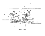
- FIG. 2B illustrates the structure of planar web 12, as viewed from one face of the web.
- the loop-engageable loops extend out of the plane of the web, from one side.
- Web 12 is composed of a non-uniform distribution of entangled fibers, with relatively high concentrations of the fibers at the bases, B, of corresponding loop structures, and relatively lower concentrations of the fibers in regions, R, lying between loop bases, B.
- the relatively high concentrations of fibers at bases B correspond to tightened fiber entanglements.
- a substantial number of the fibers in the regions, R, between loop bases are taut in the plane of the web, extending in different directions radiating from loop bases, B.
- taut we mean that a large percentage of these inter-base fibers have no give or slack, such that they may transmit an applied tensile force with little or no displacement.
- taut fiber portions extending across the sparse regions between loop bases account for some of the beneficial properties of the loop product, giving it a perceptibly high strength-to-weight ratio as a fastener component.
- a particularly visible loop base B from which taut fibers can be seen emanating in a radial pattern. Also note that there are some fibers which are wrapped at least partially about other fibers of the loop base. These wrapping fibers are the result of stretching, during which straightening fibers encounter loop fibers extending through the planar web. As the web is further stretched, the loop fibers provide obstructions about which the straightening web base fibers are trained as they are displaced within the web plane.
- the bases, B, of the loop structures contain both portions of the loop-forming fibers extending out of the plane of the web and trained portions of taut fibers lying generally in the plane of the web.
- the trained portions of the taut fibers within the loop bases therefore contribute, as the web is stretched, to the definition of the free-standing loop formations.
- these bases B become relatively rigid nodes and, importantly, provide anchoring for their associated loops.
- the stretched and stabilized web in some respects, resembles a planar truss, with its taut radiating fibers forming tensile members between base nodes.
- the taut fibers may be readily "bent" out of their plane as the web flexes, the structure retains an advantageously high flexibility while resisting elongation and shrinkage within its original plane.
- the individual fibers of loop fabric 12 shown in Fig. 2 have low denier and substantial tenacity (i.e., tensile strength per unit diameter) to work with very small hooks such as those illustrated in Fig. 1. Fibers with tenacity values of at least 2.8 grams per denier have been found to provide good closure performance, and fibers with a tenacity of at least 5 or more grams per denier (preferably even 8 or more grams per denier) are even more preferred in many instances. In general terms for a loop-limited closure, the higher the loop tenacity, the stronger the closure.
- 1 and 2 are 6 denier staple polyester fibers (cut to four inch lengths) and as a result of the method of the manufacture, are in a drawn, molecular oriented state, having been drawn with a draw ratio of at least 2:1 (i.e., to at least twice their original length) under cooling conditions that enable molecular orientation to occur, to provide a fiber tenacity of about 3.6 grams per denier.
- the fibers in this example are of round cross-section and are crimped at about 7.5 crimps per inch (3 crimps per cm). Such fibers are available from E.I. Du Pont de Nemours & Co., Inc., in Wilmington, Delaware under the designation T-3367 PE T-794W 6x4.
- the loop fiber denier should be chosen with the hook size in mind, with lower denier fibers typically selected for use with smaller hooks. For low-cycle applications for use with larger hooks (and therefore preferably larger diameter loop fibers), fibers of lower tenacity may be employed.
- fibers of other cross-sections having angular surface aspects can enhance knot tightening for certain applications.
- fibers of pentagon or pentalobal cross-section can enhance knot tightening for certain applications.
- they are selected to have a surface character that permits slippage within the knot-forming entanglements during tightening so as to enable stretching the batt without undue fiber breakage.
- the loops 14 of loop fabric 12 of this embodiment project primarily from one side of the fabric.
- the stabilizing binder in this case, is applied to the other side.
- the loop product is extremely thin for use with very small hooks.
- the product shown, for instance, works well with hooks of about 0.015 inch (0.4 mm) height and has a loop height h L (i.e., the height of loops 14 from the near general surface of fiber mat 16) of about 0.055 inch (1.40 mm).
- the loop product has an overall thickness, t, including a majority of the loops, of only about 0.090 inch (2.3 mm).
- the near surface of the mat When measuring loop height in products without a visibly distinguishable upper mat surface, we define the near surface of the mat to be the lowest planar surface above about 80 percent of the total mass of fibers.
- the loops preferably vary in height for good engagement, and the average loop height should generally be greater than the height of the hooks with which the loop product is to be used, and preferably between 2 and 10 times the head height of the hooks used for applications requiring good shear strength.
- the loops may be up to 15 times the head height of the hooks.
- the average height h L of the loops should be between about 0.012 and 0.060 inch (0.3 and 1.5 mm) for good shear performance.
- the average height of the loops should be at least 0.035 inch (0.89 mm) and may be as high as 0.250 inch (6.4 mm) for applications focusing on peel loading.
- the average loop height should generally be between about 0.020 and 0.060 inch (0.5 and 1.5 mm), and should be between about 0.5 and 0.8 times the overall thickness, t, of the loop product.
- loops 14 extend from free-standing clusters of loop fibers extending from the fibrous mat 16.
- the clusters 20 which have several monofilament loops 14 extending from a common elongated, substantially vertical trunk 22 we call “loop trees".
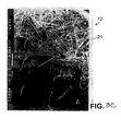
- FIG. 3C Another example of a "loop tree" is seen in Fig. 3C.
- Each loop tree 20 extends from a corresponding knot 18 in which the loops of the cluster are anchored. Interstices between individual filaments in the trunk portion 22 of each tree or at the base of each bush, and in each knot 18 provide paths for the wicking of liquid binder, under the influence of surface tension of the liquid binder, to provide additional localized stiffness and strength.
- the density of clusters in the plan view is very low (Figs. 2 and 2A), leaving sufficient room between the "branches" of neighboring trees to accommodate hooks and deflected loop material during engagement.
- Accumulations of solidified binder 21 can be seen in the knots in the highly magnified plan view of Fig. 3C. Applied in liquid form in this example, preferably before the knots are tightened, the binder contributes to securing the loops against being pulled out of the web.
- the fully engaged fastener i.e., the loop product and mating hook product together
- the fully engaged fastener has an overall thickness of only the sum of the thickness of the hook product (including hooks) and the "ground" portion of the loop product (i.e., the thickness of the mat 16 between loop clusters, Fig. 3B).
- the free standing loops of the loop product do not add to the thickness of the completed fastener.
- the combination of loop product 12 with mating hook product 10 provides a fastening of very small thickness.
- the engaged fastener of Fig. 1 has an overall thickness of only about 0.050 inch (1.3 mm; thinner, in this case, than the overall thickness of the unengaged loop product, as the taller loop clusters are somewhat compressed by the hook product engaged with shorter loop clusters).
- loop fabric formed according to the new principles is particularly flexible. Flexibility can be very important in some fastener applications, especially when the fastener must flex during use, as when used on an article of apparel.
- the loop product of the invention should have a bending stiffness of less than about 300 milligrams, preferably less than about 100 milligrams, as measured with a Gurley type tester. More details on the use of Gurley type testers can be found in Method T 543 OM-94, published in 1984 by the Technical Association of Pulp and Paper (TAPPI ).
- thermoplastic staple fibers which have substantial tenacity are preferred for making thin, low-cost loop product that has good closure performance when paired with very small molded hooks.
- polyolefins e.g., polypropylene or polyethylene
- polyesters e.g., polyethylene terephthalate
- polyamides e.g., nylon
- acrylics and mixtures, alloys, copolymers and coextrusions thereof are suitable.
- Polyester is presently preferred.
- a small percentage of metal fibers may be added.
- loop products of up to about 5 to 10 percent fine metal fiber, for example, may be advantageously employed for grounding or other electrical applications.
- binders may be employed to stabilize the fabric.
- binder we mean a material within the mat (other than the fibers forming the main fastener loops) that secures the loop fibers at associated knots.
- the binder is an adhesive.
- the binder is in the form of fibers of low-melt polymer dispersed throughout and entangled within the fabric. These low-melt fibers are melted to wet the knot-forming entanglements and then cooled and solidified to secure the loops and stabilize the fabric.
- the binder preferably fully penetrates and permeates the interstices between individual fibers in the entanglements of the mat.
- the binder When employing a liquid binder, the binder is preferably selected to have a sufficiently low viscosity and surface tension to enable it to flow into the untightened (or tightening) entanglements. In the embodiments in which the entanglements are subsequently tightened (such as the loop product shown in Fig. 2), this selected distribution of the fluid binder helps to secure the knots with minimal stiffening of the overall product and without requiring substantial amounts of binder.
- the amount and penetration of the binder should be selected to avoid substantial interference with the desired hook-engaging function of the loops while adequately stabilizing the mat and securing the loops against being pulled from their associated entanglements.
- the amount and type of binder should also be selected to be biocompatible to avoid skin irritation. As irritation can be aggravated by stiffness, preferably only enough binder to perform the above functions is applied. In some applications, for instance those in which the loop product is directly adhered to a supporting fabric and which does not require substantial fastener strength, the loop product may be provided without a binder.
- the binder also includes an organic or inorganic fire-retardant, such as antimony oxide, zinc borate, aluminum trihydrate or decabromobiphenyl oxide.
- an organic or inorganic fire-retardant such as antimony oxide, zinc borate, aluminum trihydrate or decabromobiphenyl oxide.
- the specific loop product 12 of Figs. 1 and 2 includes about one third by weight water-based acrylic binder produced by mixing 80 parts "NACRYLIC” X-4280, a self-reactive acrylic emulsion, with 20 parts "X-LINK” 2804, a self-crosslinking, polyvinyl acetate/acrylate emulsion, both available from National Starch and Resin Company in Bridgewater, New Jersey.
- loop product 12 substantially consists only of the drawn fibers of the thin mat, some of which extend out of the mat to form loops, and the binder.
- Fig. 4A shows a hook-and-loop product 22 formed by ultrasonically welding a piece of the loop material 12 of Fig. 2 to a piece of CFM-29 hook product.
- the resulting product 22 can be formed into a closed band by engaging its loops with its hooks.
- Fig. 5B is an enlarged view of stitching 24 securing the loop product to a substrate.
- another loop fabric material 26 includes, in addition to the drawn, molecularly oriented, randomly laid fibers previously described, continuous robust longitudinal monofilament fibers 28 extending substantially in one direction to augment the tensile strength of the finished fabric in the direction of the strands.
- the diameter of the longitudinal monofilaments is selected to be larger than the barbs of the needles to reduce engagement of the monofilaments by the needles during the needling process.
- Monofilaments 28 are preferably crimped to enable them to be stretched a limited amount in the machine direction as the fabric is stretched before being stabilized.
- a stretchable scrim of similarly large fibers or film may be incorporated into the web of fibers to increase tensile strength in both longitudinal and lateral directions.
- Fig. 4B illustrates a one-piece fastener product consisting of a lamination of the above-described loop material and molded hook tape.
- Product 300 has a base 302 with integrally molded hooks 304 projecting from one side and the above-described non-woven loop material 12 secured to the other side.
- the plastic from base 302 flows around and entraps some of the fibers of the base web of loop material 12, encapsulating one face of the web in thermoplastic material to form a permanent laminate of the two layers. Because of the extremely light nature of the non-woven material of the invention, care must be taken to only encapsulate the web and to leave the functional loops exposed for engagement with hooks 304.
- the properties of the non-woven material, the viscosity of the plastic and the pressure in the nip will determine the degree to which the plastic flows into the fibrous network, or put alternately, the degree to which the non-woven will imbed into the plastic.
- the resulting laminated product is particularly thin and flexible, due in part to the thinness of the loop material.
- the product of Fig. 4B may be economically formed by the process and apparatus illustrated in Fig. 5.
- Extruder barrel 308 melts and forces the molten plastic 310 through die 312 into the nip 314 between base roller 316 and cavity roller 318 containing cavities to form the hooks of a strip fastener of the well known hook and loop type.
- the strip fastener material formed in nip 314 travels around the periphery of cavity roller 318 and around stripping roller 320, which assists in pulling the finished product 300 from the cavity roll, and from there to a windup device, not shown.
- FIG. 5 illustrates a device particularly well adapted to that purpose.
- loop material 12 By introducing loop material 12 into nip 314 at the same time molten plastic 310 is forced into the nip, the loop material will bond intimately with the fastener to become an integral part of the structure of the strip fastener.
- a set of pins 322 at the edges and around the periphery of backing roller 316 carry the loop material 12 into nip 6 in a flat, unwrinkled state.
- a roll 324 of loop material 12 is mounted on a let off device and threaded around diversion roller 326 into a web straightening device 328, well known in the art as typically sold by the Fife Manufacturing Company which assures that the web of loop material is centered as it is fed onto backing roller 316 around scroll roll 330, which has ribs of elastomeric material to firmly grip the sheet and impinge it against backing roller 316 and onto pins 322. Pins 322 and roller 316 deliver the web into nip 314 along with molten plastic 310.
- molten plastic 310 As molten plastic 310 is forced by the pressure imposed upon it by the narrow space of nip 314, it flows into cavities in cavity roller 318 and also into pores in the adjacent face of the loop material being carried by backing roller 316. In this way the loop material is intimately joined to the base of the forming hook fastener tape to form laminated product 300.
- a diaper 50 has an outer shell 52 fabricated from the above-described loop product, such that it can be engaged by hooks 80 anywhere over a significant proportion of its surface, while providing the outer "wearing" surface of the article.
- a panel or patch of the loop product is laminated (directly, or via a carrier sheet,) to the outer liner of a diaper, to provide a suitably large "landing" area that hooks can engage.
- a panel of the loop product is laminated to a carrier film, which, on its back, has a layer of pressure-sensitive adhesive for automated application to diaper liners or the like during manufacture of the diaper.
- Fig. 7B shows a surgical gown 54 fabricated from the loop material of the invention and capable of being "hooked" by hooks 80 at any point over a large portion of its surface.
- a panel or patch of the loop product may be attached to the outer surface of a surgical gown.
- loop material In such applications in which the products are considered disposable after single use, the loop material only need withstand a relatively small number of hooking cycles (e.g., 3 to 5) over the product's useful life. We refer to these as "low cycle” applications. Loop products in this category may be fabricated by stretching needled fabric in excess of 100%, as much as 150% or more.
- loops can require the loop to withstand a higher number of cycles and higher stress.
- These relatively "high cycle”, high strength applications generally are achieved by forming loops with higher denier (or higher tenacity) fibers than those suitable for lower performance conditions.
- polyester fibers of 15 denier are advantageously employed for high strength high cycle applications employing large hooks such as CFM 15 (0.035 inch or 0.89 mm high) or MV 8 (0.100 inch or 2.5 mm high) or mushroom fasteners, all available from Velcro USA Inc.
- Loop products in this category may be prepared by stretching in the range of 50 percent to 100 percent stretch, for example.
- Fig. 7C shows a box 56 with hook closure strips 58 that engage loop closure strips 60 of our loop product to hold the flaps 62 of the box in a closed position.
- Loop closure strips 60 have pressure sensitive adhesive backing, by which they are permanently applied to box flaps 62. Supplied as die cut sections on a release liner, loop strips 60 can be applied to the box flaps with a common, automatic label head, for instance.
- the box is useful for applications where it must be repeatedly opened while its contents are progressively consumed, for example, a pet food box.
- a binder adhesive may be formulated to be pressure sensitive, with or without a release liner, such that the final product may be applied to a substrate by the application of pressure. Without a release liner, as the product is rolled or spooled the pressure sensitive backing lies against and adheres to the hook-engageable loops to keep the product in rolled form until unrolled by peeling, leaving a sufficient amount of undisturbed adhesive on the back of the fabric to secure the product to a substrate.
- coatings such as heat sensitive or “hot-melt” coatings, or water-activated or solvent-activated coatings, may also be used with suitable heating or application of activating fluid at the time of activation to secure the loop material to the item on which a closure is desired.
- Fig. 7D shows a polyethylene bag 64 to which a polyethylene hook strip 66 and a polyethylene loop strip 68 have been thermally bonded or welded. It can be closed in rapid fashion by simply pressing one end of the closure together by opposed fingers and sliding the fingers from one end to the other of the closure. Such a closure does not require accurate alignment of the mating features to be secured, and can enable some desirable venting and filtration through the secured closure.
- venting, filtering closure which is practically enabled by the low cost of the loop product of the invention, is useful for vegetable containers and charcoal briquette bags, for instance.
- the closure also allows equilibration of the pressure inside and outside of bags or packages constructed to travel in airplane cargo holds.
- the loop product may be flame-laminated to other materials, such as to open-cell foam.
- the flame lamination process not only adheres the loop product to the foam, but stabilizes the foam.
- Products economically produced in this manner include disposable medical devices, such as limb or joint braces, straps for colostomy bags, and blood pressure cuffs.
- Other products include merchandise and trade show displays with large surfaces of loop product upon which hooks can be used for mounting various displays.
- Fig. 7E shows the loop material described above, associated with a suitable frame as an inexpensive, replaceable filter 80. Stiffened by suitable proportions of binder and/or a stiffening agent applied to the web, the loop material is preferably permanently corrugated to increase the surface area of the filter intercepting a flow of air and to enhance the rigidity of the filter.
- Fig. 7F illustrates an example of the use of the non-woven material of the invention as a geotextile, as a silt screen for a soil drainage system.
- a trench 350 is formed in the soil at or below the footing level of a foundation, for instance, and a wide, continuous length 352 of non-woven material, formed according to the process described above, is laid along the trench.
- a layer 354 of stone is placed on the non-woven material 352 in the bottom of the trench, and a perforated or slit drain pipe 356 is laid on top of the layer 354 of stone.
- the pipe is then covered with another layer 358 of stone to form a highly permeable layer about the exterior of the pipe, the interior of which defines the drain.
- the layers of stone form open interstices for the free flow of groundwater into the pipe.
- the edges of the length 352 of non-woven material are then pulled up over the stone and overlapped to form a continuous tube about the stone and pipe.
- the edges of the non-woven material are held in this overlapped condition by a continuous length of hook fastener product 360 having hooking elements extending from one side for engaging and retaining the fibrous loops of the non-woven material.
- the trench is subsequently back-filled.
- the porous structure of the non-woven material 352 enables groundwater to drain from the surrounding soil into the stone and pipe while providing an adequate barrier to sand and silt that would otherwise clog the interstices of the stone layer and the slits in the pipe.
- the non-woven material described above may be employed in other geotextile applications, as well.
- large sheets of the material may be placed edge to edge over large areas to stabilize the boundary between different soil types.
- the fastening properties of the above-described material enable adjacent sheets to be easily joined with lengths of hook fastener product. Joining adjacent sheets of ground stabilization material with continuous fastener tape helps to keep the sheets in place and to maintain the continuity of the barrier formed by the non-woven material.
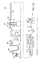
- an apparatus for producing the above-described loop material includes a feeder 110 (with, e.g., bale breakers, blender boxes or feed boxes), which feeds staple fibers of a desired length of drawn fibers to carding machines 112.
- the carding machines 112 card the staple fibers to produce carded webs of fibers 114 which are picked up by the take-off aprons 116 of crosslappers 120.
- the crosslappers 120 also have lapper aprons 118 which traverse a floor apron 122 in a reciprocating motion.
- the crosslappers lay carded webs 114 of, for example, about 12 to 18 inches (30 to 45 cm) width and about one inch (2.5 cm) thickness on the floor apron 122, to build up several thicknesses of criss-crossed web to form a batt 124 of, for instance, about 90 to 120 inches (2.3 to 3.0 m) in width and about 4 inches (10 cm) in thickness.
- a batt 124 of, for instance, about 90 to 120 inches (2.3 to 3.0 m) in width and about 4 inches (10 cm) in thickness.
- the material is stretched and pulled into a cloth-like mat consisting primarily of parallel fibers. With nearly all of its fibers extending in the carding direction, the mat has some strength when pulled in the carding direction but almost no strength when pulled in the carding cross direction, as cross direction strength results only from a few entanglements between fibers.
- the carding direction is not the machine direction of the finished product.
- the carded fiber mat is laid in an overlapping zigzag pattern, creating batt 124 of multiple layers of alternating diagonal fibers.
- the diagonal layers which extend in the carding cross direction, extend more across apron 122 than they extend along its length.
- batt which has been crosslapped to form layers extending at anywhere from about 6 to 18 degrees from the cross direction of the finished product.
- the resultant crosslapped batt 124 therefore, has more cross direction strength (i.e., across apron 122) than it has machine direction strength (i.e., along apron 122).
- the machine direction of the final product is in the same sense as the direction along apron 122.
- Batt 124 has little machine direction strength because the fiber layers are merely laid upon one another and are in no way woven together.
- the material properties and the manufacturing process can be affected by the crosslapping angle. A steeper angle may balance the cross and machine direction strengths, which may affect fastener performance and the ease of manufacturing. With more machine-directional crosslapping, in some cases the initial machine direction stretch described below may be eliminated while still obtaining a useful product.
- batt 124 is gradually compressed in a tapered nip between floor apron 122 and a moving overhead apron 138 to reduce its thickness to about one inch. A relatively thin, low density batt can thus be produced.
- Needling of batt 124 is performed in multiple, sequential needling stages in order to provide a very high density of needle penetrations without destroying the low density batt.
- felting needles are employed having fiber-engaging barbs on their sides. Needle punching gives the batt cohesion. The needle barbs pull fibers from one layer of the batt through other layers, entangling the fibers from different layers that are oriented in different directions. The resulting entanglements hold the batt together.
- the batt is passed to a first needle loom 140 with two needling stations 142 and 144 having rows of notched (i.e., barbed) needles.
- Needling station 142 needles the batt of staple fibers from its upper surface at a density in the range of 100 to 160 punches per square inch (15 to 25 per square cm). In this embodiment, the batt was needled at a density of 134 punches per square inch (21 per square cm).
- needling station 144 needles the once-needled batt a second time, with needles which penetrate the batt from its upper surface at a density in the range of 500 to 900 punches per square inch (78 to 140 per square cm) to produce a needled batt 146.
- the second needling is at a density of 716 punches per square inch (111 per square cm).
- INDA Nonwoven Fabrics Industry
- needled batt 146 is passed between drive rolls 148 and into a J-box accumulator 150 which, besides holding a bank of batt to accommodate variations in processing rates, allows the needled batt to relax and cool before entering the second needling stage.
- the needled batt 146 may be spooled after the first needling stage, with subsequent operations performed on a second line. If materials and conditions allow, the needled batt may be passed directly from the first needling stage to the second needling stage without accumulation, but care should be taken to ensure that the batt is sufficiently cool and relaxed to withstand the second needling stage.
- needled batt 146 is pulled through a guider/spreader 152 (of, e.g., the one-over-two configuration) to properly apply light tension to the batt as is customary for needling, without significant stretching of the batt. It then passes through a second needle loom 154 for a second needling stage. The operation of this second stage is referred to "super needling", as it is a very dense secondary needling operation and produces many loops of substantial loft.
- Loom 154 has a single needling station 156 in which needled batt 146 is needled from the lower side to produce high-loft loops extending from the upper side.
- the sharp tips of the notched needles of loom 154 are extended a substantial distance (e.g., about 1/4 inch or 6.3 mm) beyond the thickness of the batt in the opposite direction as the needles of the first needling station, pushing individual fibers away from the bulk of the batt to form upstanding loops.
- the loops may be formed of fibers which originally lay on the opposite side of the batt, or from fibers drawn from the middle of the batt. In either case, the needles drag fibers out of the batt and leave them extending from the bulk of the batt as loops which give one side of the super-needled batt a fuzzy appearance.
- This super-needling process does not require special needling bedplates or supporting brushes into which the needles extend, such as are employed in structured or random velour looms, although such techniques may be employed to advantage, e.g., where large loops are desired for use with large hooks.
- the super-needling is primarily characterized as an extremely dense needling, on the order of about 1000 to 2000 punches per square inch (155 to 310 per square cm), or preferably about 1400 punches per square inch (217 per square cm).
- Standard barbed needles are employed, such as triangular section 15x18x42x3 C222 G3017 felting needles from Groz-Beckert.
- needle loom 154 has an additional, second needling station 158. After producing high-loft loops extending from one surface, the batt is super needled in the other direction to produce loops extending from its other surface, such that both sides have extended loops.
- super-needled batt 160 is split into two running 45 inch (114 cm) widths and spooled on rolls 162. As shown in Fig. 11, the fibers of batt 160 have been entangled by the needle punching process to create loose entanglements throughout the batt. At this stage, the batt is not an acceptable loop product for many hook-and-loop fastening applications, as the individual loops may be relatively easily pulled away from the batt and are not well anchored at the entanglements.
- the second needling stage is omitted.
- needle looms 142 and 144 of the first needling stage are configured to super-needle the batt in both directions.
- Loom 142 needles the batt from the top at a rate of 254 punches per square inch (39 per square cm), with the needles penetrating the batt and extending through the bottom of the batt a distance of 10.2 millimeters.
- Loom 144 then needles the batt from the bottom at a rate of 254 punches per square inch (39 per square cm), with the needles penetrating the batt and extending through the top of the batt a distance of 7.1 millimeters to form loops on the top side of the batt.
- the needles of loom 144 tend to take fibers that have been pushed through the bottom of the batt by the needles of loom 142 and force them back up through the batt in the formation of topside loops. Although this process results in a relatively small number of loops on the bottom of the finished product, due to the first needling of loom 142, the resulting product has been found to be useful for some applications.
- the needling density, speed, and penetration of looms 142 and 144 may be varied to produce a product with substantially no backside loops, or with hook-engageable loops extending from both sides.
- Batt 160 in this example, has an overall thickness, including loops, of about 3/16 inch (4.8 mm) and a weight of between about 2 and 4 ounces per square yard (68 and 135 grams per square meter).
- a spooled length of super-needled batt 160 is spooled from roll 162 by drive rolls 165 and into a J-box accumulator 166, allowing roll 162 to be replaced and the batt spliced without interrupting further processes.
- the J-box also allows the batt to recover from any elastic deformation caused by the spooling process.
- Batt 160 is pulled from accumulator 166 through a guider 168 to center the batt in the cross-machine direction.
- Guider 168 includes three rolls in a two-over-one configuration.
- the first and second rolls 170 and 172 have left and right herringbone pattern scroll surfaces originating at the center of the roll that, being slightly overdriven, urge any wrinkles in the batt toward its edges to remove them.
- the third roll, roll 174 is a split braking roll to controllably tension either half of the batt to guide the fabric to the left or right as desired.
- the batt passes through a tension controller 176 that maintains a desired tension in the batt through the subsequent binder application process.
- Controlling the difference between the speed of tension controller 176 and downstream drive rolls 202 applies a desired amount of machine direction stretch to the batt prior to cross-machine stretching. In some cases, no substantial machine direction stretch is purposefully applied, any noted machine direction lengthening being due only to minimal web processing tension in the supply batt. In other cases, machine direction stretch is purposefully induced by running drive rolls 202 faster than tension controller 176.
- batt 160 is next passed through a coating station 190 in which a foamed, water-based adhesive 192 (i.e., a water-based adhesive, whipped to entrain air) is applied to the back side 194 of the batt across its width.
- a foamed, water-based adhesive 192 i.e., a water-based adhesive, whipped to entrain air
- the foamed liquid adhesive is pumped at a controlled rate through a long, narrow aperture 196 in the upper, surface of the applicator 198 as the batt is wiped across the aperture, thereby causing the adhesive to partially penetrate the thickness of the batt.
- Positioning bars 200, on either side of aperture 196, are raised and lowered to control the amount of pressure between batt 160 and applicator 198.
- the depth of penetration of the adhesive into the batt is controlled (e.g., by the flow rate and consistency of adhesive 192, the speed of batt 160 and the position of bars 200) to sufficiently coat or penetrate enough of the fiber entanglements to hold the product in its final form, while avoiding the application of adhesive 192 to the loop-forming fiber portions of the front side 188 of the batt.
- the foaming of the liquid adhesive before application helps to produce an even coating of the back side of the batt and helps to limit penetration of the fluid adhesive into the batt.
- the semi-stable foam After the semi-stable foam is applied it has a consistency similar to heavy cream, but the bubbles quickly burst to leave a liquid coating that flows as a result of wetting and surface tension, into the tightening fiber entanglements.
- the foam may have a thicker consistency, more like shaving cream, to further reduce the penetration into the batt and form more of a distinct resinous backing.
- a non-collapsible (i.e., stable) foam of urethane or acrylic, for instance, is useful to produce a radio frequency-weldable backing which functions as a water barrier. Such a product has particular application to disposable garments and diapers.
- the binder e.g., adhesive 192
- the binder is at least partially in liquid form to wick into the entanglements before and while they are subsequently tightened during stretching.
- the capillary action of the liquid binder is such that examination of the finished product shows that the binder is almost exclusively at the knots of the web (at the base of the loops, for instance), and therefore does not tend to adversely affect either the functionality of the free-standing loops or the flexibility of the web.
- the material is subjected to stretching in the plane of the web.
- the web is wound through variable speed drive rolls 202 and onto a tenter frame 204 for cross-machine stretching (i.e., stretching in the cross-machine direction).
- the speed of drive rolls 202 is adjustable, with respect to both tension control 176 and the rails 206 of the tenter frame, to cause a predetermined amount of machine direction stretch in the batt, either between tension control 176 and drive rolls 202, or between drive rolls 202 and frame rails 206, or both.
- no permanent machine direction stretch is applied, but the batt is nevertheless held in tension to control adhesive penetration and maintain proper frame rail pin spacing.
- the batt is generally stretched, in total, between about 20 percent and 50 percent in the machine direction before tentering.
- the 45 inch wide batt 160 is engaged along its edges by pins of frame rails 206 that maintain the machine-direction dimension of the material as it is stretched in the cross-machine direction.
- the spacing (of, e.g., about 3/16 inch or 4.8 mm) between adjacent pins is maintained throughout the length of the tenter frame, such that no additional machine-direction stretch is applied. Due to the needling, batt 160 should have enough tensile strength to be properly engaged by the rail pins and withstand the subsequent cross-machine stretching.
- Tenter frame 204 has a tapered section where the rails 206 separate at a constant, adjustable range rate over a machine-direction length of about 10 feet (3 meters) to a final width which can range from 45 inches (114 cm) to about 65 to 69 inches (165 to 175 cm). This equates to a cross-machine stretch, in this particular embodiment, of about 50 percent.
- the batt should be stretched to increase its area by at least about 20 percent (we call this "percent areal stretch"), preferably more than about 60 percent areal stretch and more preferably more than about 100 percent areal stretch, to increase the area of the product while tightening the binder-containing entanglements of the batt that contribute to improvement in the strength of anchorage of the individual loops.
- percent areal stretch preferably more than about 60 percent areal stretch and more preferably more than about 100 percent areal stretch
- the super-needled batt described above was stretched from an initial width of 45 inches (114 cm) to 65 inches (165 cm), softened (by adding a softener), slit to a 45 inch (114 cm) width, stretched a second time to a 65 inch (165 cm) width before applying a binder, and still had useful, hook-engageable loops. In some cases final product widths of 6 to 8 feet (1.8 to 2.4 meters) or even much more can be achieved.
- the non-woven web starting material used to manufacture the loop component is a fairly dense, needle punched, non-woven web of fibers lying in an apparently chaotic and tangled manner.
- One side, the "fuzzy side" has an excess of large, loose loop fibers created during a second needle punching process.
- the web is first stretched to 130 percent of its initial length in the machine direction. This stretching results in necking -- the material narrows to 80 percent of its initial width, from 45 inches (114 cm) to 36 inches (91 cm). It is then coated with a binder. Next, it is stretched to 175% of its necked width, from 36 inches (91 cm) to 63 inches (160 cm). During this process the material becomes much more sparse, with spider-like clusters of fiber (see bases B of Fig. 2B) serving to anchor the loop.
- the mechanism by which this change occurs relates to the method by which initial/non-woven web is manufactured.
- the fact that the fibers are oriented closer to cross machine direction means that a smaller elongation is required before the fibers are close enough to the cross direction to experience tension.
- Tension when applied, causes the fibers to try to straighten themselves out and re-orient into the cross machine direction. If the web were not previously needle punched, the material would probably lose all cohesion at this point. However, the needle punching of the web causes fibers from different layers with different orientations to entangle one another. Because of these entanglements, the fibers cannot straighten.
- each spider forms at a point where a needle caused an entanglement of multiple fibers, which tried to pull apart during the cross direction stretch.
- the bunching of the entanglements gives them the spider like appearance.
- Each loop of the fuzzy side corresponds to a point where a needle was punched through; consequently, after the cross direction stretch each fuzzy side loop lies at the center of a corresponding spider-like knot. This was seen in one experiment where the functional loops (i.e., the outer region of the fuzzy side) of the product were colored purple.
- the fibers are already more cross-directional than machine-directional, and because the cross direction stretch applied is greater, the fibers are placed under tension during cross direction elongation. Fibers entangled during needle punching tend to clump together, and as the fibers tend to straighten, these entanglements form spider-like radial patterns of fibers.
- spiders form at the location of functional loops created by deep needle punching, the fibers of which have been drawn through some or all of the web. Consequently, the loop fibers entangle the other fibers and form spiders. This means that in the finished product, the loops have spiders at their base, locking the loop fibers into the web.
- loop trees or loop formations correspond to locations where the batt was punched during super-needling
- the resulting "orchard" of loop formations does not exhibit the same ordered pattern, after the web is stretched, as might be anticipated by the pattern of punches of the needling process.
- the arrangement of loop formations is randomized during the stretching process, as distances between entanglements change as a function of the properties, direction and number of the fibers connecting various nodes.
- the resulting product has no apparent order to the arrangement of loops extending from its surface.
- the stretched batt is held on frame rails 206 in its stretched condition it is passed through an oven 208 in which the product is heated to dry and cross-link acrylic binder 192 and stabilize the dimensional integrity of the batt.
- Oven 208 is essentially a convection drier with air venturi nozzles which blow hot air up into and down onto the web to evaporate some of the water of the adhesive.
- the heating time and temperature are about one minute and 375 degrees F (190 degrees C), respectively.
- the batt is retained on frame rails 206 for secondary coating passes through additional coating stations and drying ovens, thereby building up a desired laminate structure for particular applications.
- hook-engageable loops are formed on both sides of the web by needling, by the super-needling techniques acting on staple fibers that have been described, or by other known techniques.
- the web After forming the loops the web is passed through a bath of binder.
- the binder In some cases, where the loops are relatively stiff and the binder is of suitably low viscosity, after removal from the bath the binder drains from the loops and the loops, by their own resiliency and stiffness resume their free-standing stance while capillary action retain the binder in the center of the fabric. The web is then subjected to stretching and curing as above.
- auxiliary means are employed to remove excess binder after passing through the bath, as by passing the fabric through a nip of squeeze rolls, or by subjecting both sides of the fabric to an air knife, or by blotting followed, in each case for instance by blowing air or otherwise loosening the loops and causing them to stand upright.
- Heat fusible fibers or other material colored black or otherwise adapted to absorb radiant heat may be activated by radiant heaters to bind the ground portion of the fabric following stretching. Care must be taken, in such instances, to avoid mitigation of the engagement properties of the free-standing loops.
- the stretched batt exits oven 208 still attached to the pins, and is then pulled from the pins by a de-pinning device 210 and a pair of drive rolls 212.
- the finished, wide batt is then slit, if desired, into appropriate multiple widths by a slitter 214 and spooled on a driven surface winder 216.
- a dancer 218 between drive rolls 212 and slitter 214 monitors the tension in the batt to control the speed of winder 216.
- Slitter 214 can also be used to trim off the edges of the batt that include the material outboard of the frame rails through the tenter frame.
- the finished batt can be brushed before or after spooling to disentangle loosely-held loop fibers to improve the consistency of the closure performance between the first and subsequent engagements with a hook product.
- an alternative process employs heated rolls or "hot cans" 209 or platens to stabilize the back side of the fabric in its stretched condition.
- This embodiment does not require a coating or adhesive when using thermoplastic fibers, as the fibers are locally fused together by heat. Cooled rolls 211 engage the loop side of the fabric during passage, to prevent damage to the hook-engageable loops.
- the longitudinal continuous fiber strands 28 are added to the batt prior to needle punching. These fibers are preferably crimped enough to allow the fibers to retain their integrity after the needle-punching process, to be stretched a limited amount in the machine direction as the batt is stretched.
- the above-described stretching technique can be employed to advantage on other stretchable, loop-defining non-woven webs.
- the invention is not to be limited to the use of needled webs. Webs formed by hydro or air current entanglement can, for instance, be employed.
- non-woven materials formed of staple fibers to take advantage of their drawn, molecular oriented structure, or other fibers of the substantial tenacity.
Landscapes
- Health & Medical Sciences (AREA)
- Engineering & Computer Science (AREA)
- Heart & Thoracic Surgery (AREA)
- Mechanical Engineering (AREA)
- Epidemiology (AREA)
- Biomedical Technology (AREA)
- Textile Engineering (AREA)
- Vascular Medicine (AREA)
- Life Sciences & Earth Sciences (AREA)
- Animal Behavior & Ethology (AREA)
- General Health & Medical Sciences (AREA)
- Public Health (AREA)
- Veterinary Medicine (AREA)
- Nonwoven Fabrics (AREA)
- Slide Fasteners, Snap Fasteners, And Hook Fasteners (AREA)
Abstract
Claims (52)
- Composant de fixation à bouclettes d'une attache à crochets et à bouclettes, comprenant un tissu non tissé (12) de fibres emmêlées, ayant un corps en tissu généralement plan (16), des fibres s'étendant depuis au moins une face dudit corps sous la forme de bouclettes (14) pouvant être engagées dans des crochets, caractérisé en ce que :- le tissu (12), y compris le corps en tissu (16) et les bouclettes (14), a un poids inférieur à environ 4 onces par yard carré (135 grammes par mètre carré) ;- le corps en tissu comprend une répartition non uniforme de fibres dans laquelle des fibres sont dans des concentrations relativement hautes dans les régions des bases (B) des bouclettes (14) pouvant être engagées dans des crochets, et dans des concentrations relativement plus basses dans des régions (R) disposées entre les bases (B) des bouclettes ; et- un nombre important de fibres dans des régions (R) de plus basse concentration sont tendues dans le plan du corps en tissu (16) et s'étendent dans différentes directions en rayonnant depuis les bases (B) des bouclettes (14).
- Composant de fixation à bouclettes selon la revendication 1, caractérisé en ce que les bases (B) des bouclettes (14) contiennent des parties tendues de fibres du corps en tissu, lesquelles sont traînées autour des fibres formant des boucles.
- Composant de fixation à bouclettes selon la revendication 2, caractérisé en ce que des fibres tendues des bases (B) contribuent à définir des formations faisant saillie (20) qui s'étendent depuis le plan du corps en tissu (16) et qui contiennent les bouclettes (14) pouvant être engagées dans des crochets.
- Composant de fixation à bouclettes selon la revendication 3, caractérisé en ce que les formations faisant saillie (20) comprennent des troncs allongés (22), des bouclettes (14) pouvant être engagées dans des crochets s'étendant depuis chacun desdits troncs.
- Composant de fixation à bouclettes selon l'une quelconque des revendications précédentes, caractérisé en ce que les concentrations relativement hautes de fibres sur les bases (B) des bouclettes pouvant être engagées dans des crochets définissent des emmêlements denses de fibres.
- Composant de fixation à bouclettes selon l'une quelconque des revendications précédentes, caractérisé en ce que le poids combiné du corps en tissu (16) et des bouclettes (14) est inférieur à environ 2 onces par yard carré (68 grammes par mètre carré).
- Composant de fixation à bouclettes selon l'une quelconque des revendications précédentes, caractérisé en ce que les bouclettes (14) sont disposées d'un côté à un autre du corps en tissu (16) dans un schéma relativement aléatoire.
- Composant de fixation à bouclettes selon l'une quelconque des revendications précédentes, caractérisé en ce qu'un liant fluide solidifié (21) est concentré sur les bases (B) des bouclettes.
- Composant de fixation à bouclettes selon la revendication 8, caractérisé en ce que le liant fluide solidifié (21) est sélectionné depuis le groupe constitué d'acryliques, d'uréthanes, de polyvinyles, de formaldéhydes, de glyoxal et d'époxydes.
- Composant de fixation à bouclettes selon l'une ou l'autre des revendications 8 et 9, caractérisé en ce que le liant fluide solidifié (21) est configuré sur les bases (B) des bouclettes au moins partiellement comme le résultat d'un flux capillaire avant la solidification.
- Composant de fixation à bouclettes selon l'une quelconque des revendications 8 à 10, caractérisé en ce que le liant fluide solidifié (21) représente entre environ 20 et 40 pour cent du poids total, de préférence environ un tiers du poids total du tissu (12), y compris les bouclettes (14).
- Composant de fixation à bouclettes selon l'une quelconque des revendications 1 à 7, combiné à une couche (302) de matériau thermoplastique, dans lequel une seconde face du corps en tissu (16) étant opposée à la face depuis laquelle s'étendent les bouclettes (14) pouvant être engagées dans des crochets, est encapsulée dans la couche de matériau thermoplastique.
- Composant de fixation à bouclettes selon la revendication 12, caractérisé en ce que des éléments à crochets (304) sont moulés intégralement sur une surface de la couche (302) de matériau thermoplastique.
- Composant de fixation à bouclettes selon l'une quelconque des revendications précédentes, caractérisé en ce que des fibres thermoplastiques du tissu (12) sont thermo-soudées sur les bases (B) des bouclettes (14) pouvant être engagées dans des crochets.
- Composant de fixation à bouclettes selon l'une quelconque des revendications précédentes, formé à partir d'une batte de départ aiguilletée non tissée (160) d'une dimension donnée, caractérisé en ce que le tissu (12) du composant de fixation à bouclettes est, dans son plan général d'extension, dans un état étiré stabilisé d'une surface d'au moins 20 pour cent plus grande, de préférence d'une surface d'au moins 50 pour cent plus grande, et de manière encore plus préférentielle d'une surface d'au moins 100 pour cent plus grande que la surface de la batte de départ (160).
- Composant de fixation à bouclettes selon la revendication 15, caractérisé en ce que le tissu (12) est dans un état étiré d'au moins 20 pour cent dans au moins une première direction dans le plan général d'extension du tissu (12).
- Composant de fixation à bouclettes selon la revendication 15, caractérisé en ce que le tissu (12) est dans un état étiré d'au moins 20 pour cent dans chacune des deux directions orthogonales dans le plan général d'extension du tissu.
- Composant de fixation à bouclettes selon l'une quelconque des revendications 15 à 17, caractérisé en ce que la batte de départ (160) comprend des couches de fibres généralement parallèles, des fibres de certaines couches étant orientées selon des angles aigus par rapport aux fibres d'autres couches, et caractérisé en ce que, comme un résultat de l'étirement, les angles aigus entre des fibres du corps en tissu (16) qui correspondent aux différentes couches de la batte de départ (160) sont généralement plus grands que des angles correspondants dans la batte de départ (160), tandis qu'au moins un grand nombre de fibres qui correspondent à chaque couche restent relativement parallèles.
- Composant de fixation à bouclettes selon la revendication 18, caractérisé en ce que les couches d'une batte de départ (160) s'étendant longitudinalement s'étendent de manière prédominante transversalement d'un côté à l'autre de la batte, et caractérisé en ce que, comme un résultat de l'étirement longitudinal de la batte de départ (160), les angles aigus entre des fibres du corps en tissu (16) qui correspondent aux différentes couches de la batte de départ (160) sont généralement plus grands que des angles correspondants dans la batte de départ (160).
- Composant de fixation à bouclettes selon l'une quelconque des revendications précédentes, ayant une épaisseur hors tout (t), y compris le corps en tissu (16) et une majorité des bouclettes (14), inférieure à environ 0,150 pouce (4,0 mm), de préférence inférieure à environ 0,100 pouce (2,5 mm).
- Composant de fixation à bouclettes selon l'une quelconque des revendications précédentes, caractérisé en ce que les bouclettes (14) pouvant être engagées dans des crochets s'étendent depuis les bases (B) de bouclettes associées à l'intérieur du plan du tissu à une hauteur de bouclette moyenne (hL) entre environ 0,020 et 0,060 pouce (0,5 et 1,0 mm), mesurée comme la distance perpendiculaire depuis le corps en tissu (16).
- Composant de fixation à bouclettes selon l'une quelconque des revendications précédentes, caractérisé en ce que le tissu (12) a une épaisseur hors tout (t), y compris le corps en tissu (16) et une majorité des bouclettes (14), et dans le quel la hauteur de bouclette moyenne (hL) est environ entre 0,5 et 0,8 fois plus épaisse que l'épaisseur hors tout (t) du produit.
- Composant de fixation à bouclettes selon l'une quelconque des revendications précédentes, ayant entre environ 50 et 1000 emmêlements de fibres denses par pouce carré (8 et 160 par centimètre carré) de surface de tissu, depuis lesquels s'étendent des bouclettes (14) pouvant être engagées dans des crochets.
- Composant de fixation à bouclettes selon l'une quelconque des revendications précédentes, caractérisé en ce que le tissu (12) est généralement composé de fibres ayant une ténacité d'au moins 2,8 grammes par denier, de préférence d'au moins 5,0 grammes par denier, et de manière encore plus préférentielle d'au moins 8,0 grammes par denier.
- Composant de fixation à bouclettes selon l'une quelconque des revendications précédentes, caractérisé en ce que les bouclettes (14) s'étendent depuis le corps en tissu (16) à des hauteurs variées (hL) pour former une disposition à plusieurs niveaux de bouclettes (14) pouvant être engagées dans des crochets.
- Composant de fixation à bouclettes selon l'une quelconque des revendications précédentes, ayant une raideur de Gurley inférieure à environ 300 milligrammes.
- Composant de fixation à bouclettes selon l'une quelconque des revendications précédentes, comprenant des cordons de consolidation séparés (28) qui s'étendent au moins dans une direction à l'intérieur du plan du corps en tissu (16).
- Boîtier (56), comprenant une première partie de fermeture (60) ayant des bouclettes et une seconde partie de fermeture (58) ayant des crochets construits pour engager les bouclettes de la première partie de fermeture afin de maintenir le boîtier (56) dans une position ouverte ou fermée, le boîtier étant caractérisé en ce que la première partie de fermeture (60) comprend le produit de fixation à bouclettes selon l'une quelconque des revendications précédentes.
- Boîtier selon la revendication 28, caractérisé en ce que la première et la seconde partie de fermeture (58 et 60) ont une épaisseur hors tout combinée, engagée et au repos, inférieure à environ 0,075 pouce (1,9 mm).
- Article de vêtement à usage unique (50, 54), ayant une étoffe et une fixation avec des éléments à crochets disposés pour engager des bouclettes de l'étoffe afin de former une attache détachable pour maintenir l'article de vêtement (50, 54) sur la personne qui en est revêtue, l'article de vêtement étant caractérisé en ce que l'étoffe comprend le composant de fixation à bouclettes selon l'une quelconque des revendications 1 à 27.
- Filtre à air (80), caractérisé en ce que le filtre comprend le produit de fixation à bouclettes selon l'une quelconque des revendications 1 à 27, lequel est disposé pour intercepter et filtrer un flux d'air.
- Barrière géotextile (352), caractérisée en ce que la barrière comprend le produit de fixation à bouclettes selon l'une quelconque des revendications 1 à 27, lequel est disposé pour intercepter et filtrer un flux de la nappe phréatique.
- Barrière géotextile (352), caractérisée en ce que la barrière comprend le produit de fixation à bouclettes selon l'une quelconque des revendications 1 à 27, lequel est disposé pour stabiliser une limite de couche dans le sol.
- Produit de fixation, ayant une base polymère en forme de feuille (302) et comprenant des crochets (304) moulés intégralement avec et s'étendant depuis un côté de la base, et un matériau à bouclettes lié de manière permanente à et s'étendant sur un côté opposé de la base, le produit étant caractérisé en ce que le matériau à bouclettes du produit comprend le matériau de fixation à bouclettes (12) selon l'une quelconque des revendications 1 à 27, et en ce que les bouclettes (14) du matériau de fixation à bouclettes (12) sont adaptées pour être engagées par les crochets (304) du produit.
- En combinaison,- un produit de fixation à crochets (10) ayant des crochets s'étendant depuis une surface de celui-ci ; et- le produit de fixation à bouclettes selon l'une quelconque des revendications 1 à 27, les crochets du produit de fixation à crochets étant adapté pour engager les bouclettes (14) du produit de fixation à bouclettes afin de former une attache détachable.
- Combinaison selon la revendication 35, caractérisée en ce que le produit de fixation à crochets (10) et le produit de fixation à bouclettes ont une épaisseur hors tout combinée, engagée et au repos, inférieure à environ 0,075 pouce (1,9 mm), de préférence inférieure à environ 0,050 pouce (1,27 mm).
- Méthode de formage d'un composant de fixation à bouclettes pour la fixation par des crochets et des bouclettes depuis une batte non tissée généralement plane (160) de fibres emmêlées, la méthode étant caractérisée par :- l'étirement de la batte (160) dans au moins une direction, produisant de cette manière un tissu étiré (12) ayant un corps en tissu généralement plan (16) et présentant une répartition non uniforme de fibres, comportant des fibres dans des concentrations relativement hautes dans des régions de bases (B) de bouclettes (14) pouvant être engagées dans des crochets s'étendant depuis le corps en tissu (16) ainsi que des fibres dans des concentrations relativement plus basses des régions (R) du tissu entre les bases (B) des bouclettes, comprenant :- un nombre important de fibres dans des régions (R) de plus basse concentration qui sont tendues dans le plan du corps en tissu (16) et qui s'étendent dans différentes directions en rayonnant depuis les bases (B) des bouclettes (14) ; et- la stabilisation du tissu (12) dans son état étiré.
- Méthode selon la revendication 37, caractérisée en ce que le tissu (12) est stabilisé dans son état étiré par la solidification d'un liant fluide (21) appliqué sur le corps en tissu (16) dans des conditions qui concentrent le liant sur les bases (B) des bouclettes.
- Méthode selon la revendication 37, caractérisée en ce que le tissu (12) est d'un poids inférieur à environ 4 onces par yard carré (135 grammes par mètre carré).
- Méthode selon la revendication 39, caractérisée en ce que l'étirement provoque que des fibres tendues du corps en tissu soient traînées autour des fibres formant des boucles dans les bases (B) des bouclettes (14).
- Méthode selon l'une quelconque des revendications de méthode précédentes, caractérisée en ce que la batte est étirée d'une manière telle que les concentrations relativement hautes de fibres sur les bases (B) des bouclettes pouvant être engagées dans des crochets définissent des emmêlements de fibres denses.
- Méthode selon l'une quelconque des revendications de méthode précédentes, caractérisée en ce que la batte est étirée de manière à produire un tissu (12) ayant un poids, y compris les boucles (14), inférieur à environ 2 onces par yard carré (68 grammes par mètre carré).
- Méthode selon l'une quelconque des revendications de méthode précédentes, caractérisée en ce que le tissu (12) est stabilisé dans son état étiré par la solidification d'un liant fluide (21) appliqué sur le corps en tissu (16) dans des conditions qui concentrent le liant sur les bases (B) des bouclettes.
- Méthode selon la revendication 43, caractérisée en ce que le liant fluide (21) est appliqué avant au moins une partie de l'étirement.
- Méthode selon la revendication 43, caractérisée en ce qu'une quantité sélectionnée de liant (21) est appliquée de telle sorte que le liant représente entre environ 20 et 40 pour cent du poids total, de préférence environ un tiers du poids total du tissu (12), y compris les bouclettes (14).
- Méthode selon l'une quelconque des revendications de méthode précédentes, caractérisée en ce que la batte (160) est prévue avec des fibres thermoplastiques fusibles noyées dedans, et en ce que le tissu étiré est stabilisé dans des conditions qui provoquent que les fibres thermoplastiques fusibles soient thermo-soudées sur les bases (B) des bouclettes (14) pouvant être engagées dans des crochets.
- Méthode selon l'une quelconque des revendications de méthode précédentes, caractérisée en ce que le tissu (12) est stabilisé dans un état étiré dans lequel le tissu a, dans son plan général d'extension, a une surface d'au moins 20 pour cent plus grande, de préférence d'une surface d'au moins 50 pour cent plus grande, et de manière encore plus préférentielle d'une surface d'au moins 100 pour cent plus grande que la surface de la batte de départ (160) avant l'étirement.
- Méthode selon la revendication 47, caractérisée en ce que la batte (160) est étirée d'au moins 20 pour cent dans une première direction dans le plan général d'extension du corps en tissu (16).
- Méthode selon la revendication 47, caractérisée en ce que la batte (160) est étirée d'au moins 20 pour cent dans chacune des deux directions orthogonales dans le plan général d'extension du corps en tissu (16).
- Méthode de filtrage de l'air, caractérisée par la disposition du tissu (12) du produit de fixation à bouclettes selon l'une quelconque des revendications 1 à 27 pour intercepter un flux d'air qui doit être filtré.
- Méthode de filtrage de la nappe phréatique, caractérisée par la disposition du tissu (12) du produit de fixation à bouclettes selon l'une quelconque des revendications 1 à 27 pour intercepter un flux de la nappe phréatique, lequel doit être filtré, et par la retenue du tissu dans une position en engageant les bouclettes (14) du produit de fixation à bouclettes avec une longueur de bande de fixation à crochets (360).
- Méthode de stabilisation du sol, caractérisée par la disposition du tissu (12) du produit de fixation à bouclettes selon l'une quelconque des revendications 1 à 27 entre des couches adjacentes du sol, lesquelles doivent être stabilisées, et par la retenue du tissu dans une position en engageant les bouclettes (14) du produit de fixation à bouclettes avec une longueur de bande de fixation à crochets (360).
Applications Claiming Priority (3)
| Application Number | Priority Date | Filing Date | Title |
|---|---|---|---|
| US922292 | 1992-07-30 | ||
| US08/922,292 US6342285B1 (en) | 1997-09-03 | 1997-09-03 | Fastener loop material, its manufacture, and products incorporating the material |
| PCT/US1998/018401 WO1999011452A1 (fr) | 1997-09-03 | 1998-09-03 | Matiere a bouclettes, son procede de fabrication et son utilisation dans des produits |
Publications (3)
| Publication Number | Publication Date |
|---|---|
| EP1017562A1 EP1017562A1 (fr) | 2000-07-12 |
| EP1017562A4 EP1017562A4 (fr) | 2004-11-24 |
| EP1017562B1 true EP1017562B1 (fr) | 2007-06-20 |
Family
ID=25446841
Family Applications (1)
| Application Number | Title | Priority Date | Filing Date |
|---|---|---|---|
| EP19980950607 Expired - Lifetime EP1017562B1 (fr) | 1997-09-03 | 1998-09-03 | Matiere a bouclettes, son procede de fabrication et son utilisation dans des produits |
Country Status (11)
| Country | Link |
|---|---|
| US (2) | US6342285B1 (fr) |
| EP (1) | EP1017562B1 (fr) |
| JP (1) | JP2001514346A (fr) |
| KR (1) | KR20010023582A (fr) |
| CN (1) | CN1118366C (fr) |
| AU (1) | AU748531B2 (fr) |
| CA (1) | CA2301591A1 (fr) |
| DE (1) | DE69837969T2 (fr) |
| ES (1) | ES2288767T3 (fr) |
| IL (1) | IL134541A0 (fr) |
| WO (1) | WO1999011452A1 (fr) |
Families Citing this family (59)
| Publication number | Priority date | Publication date | Assignee | Title |
|---|---|---|---|---|
| US6235369B1 (en) * | 1997-09-03 | 2001-05-22 | Velcro Industries B.V. | Strip-form fastening and dispensing |
| US6869659B2 (en) * | 1997-09-03 | 2005-03-22 | Velcro Industries B.V. | Fastener loop material, its manufacture, and products incorporating the material |
| CA2373982A1 (fr) * | 1999-05-28 | 2000-12-07 | George A. Provost | Presentoirs et decorations utilisant des fixations detachables |
| KR20010077591A (ko) * | 2000-02-03 | 2001-08-20 | 복성해 | 아라니콜라 프로테오리티쿠스에서 분리한 신규 금속성단백질 분해효소 및 그의 유전자 |
| ES2299479T3 (es) * | 2000-03-14 | 2008-06-01 | Velcro Industries B.V. | Cierre de gancho y presilla. |
| CA2435748A1 (fr) | 2001-01-31 | 2002-08-08 | Velcro Industries B.V. | Crochet a connexion directe |
| DE10108092B4 (de) * | 2001-02-19 | 2007-01-04 | Carl Freudenberg Kg | Verfahren zur Herstellung eines Tuftingträgers |
| US7785095B2 (en) | 2001-03-14 | 2010-08-31 | Velcro Industries B.V. | Molding apparatus and related methods |
| US20020132087A1 (en) * | 2001-03-14 | 2002-09-19 | Wolfgang Coronel | Female engaging surface fastener having a backing and method of making same |
| EP1408787B1 (fr) * | 2001-06-12 | 2007-08-15 | Velcro Industries B.V. | Materiaux a crochets pour une fermeture par contact |
| US20030232170A1 (en) * | 2002-06-12 | 2003-12-18 | Gillette Samuel Mark | Spunlaced loop material for a refastenable fastening device and methods of making same |
| AU2003268133A1 (en) * | 2002-08-20 | 2004-03-11 | Velcro Industries B.V. | Printable fastener composites |
| EP1550101A1 (fr) * | 2002-08-20 | 2005-07-06 | Velcro Industries B.V. | Stratifies a fermeture imprimables destines a des systemes d'affichage et de jeu |
| DE60329609D1 (de) * | 2002-08-20 | 2009-11-19 | Velcro Ind | Flexibles Laminatmaterial zum Verkleiden einer Gebäudefläche mit Schlingen für eine Befestigung durch Klettverschluss |
| US20040063369A1 (en) * | 2002-09-30 | 2004-04-01 | Jung Yeul Ahn | Nonwoven loop material and process and products relating thereto |
| US7190986B1 (en) * | 2002-10-18 | 2007-03-13 | Nellcor Puritan Bennett Inc. | Non-adhesive oximeter sensor for sensitive skin |
| US8753459B2 (en) * | 2002-12-03 | 2014-06-17 | Velcro Industries B.V. | Needling loops into carrier sheets |
| US7547469B2 (en) | 2002-12-03 | 2009-06-16 | Velcro Industries B.V. | Forming loop materials |
| US20050196583A1 (en) * | 2002-12-03 | 2005-09-08 | Provost George A. | Embossing loop materials |
| ES2302974T3 (es) * | 2002-12-03 | 2008-08-01 | Velcro Industries B.V. | Perforacion con aguja a traves de laminas de soporte para formar bucles. |
| US20050196580A1 (en) * | 2002-12-03 | 2005-09-08 | Provost George A. | Loop materials |
| US20050217092A1 (en) * | 2002-12-03 | 2005-10-06 | Barker James R | Anchoring loops of fibers needled into a carrier sheet |
| US7465366B2 (en) * | 2002-12-03 | 2008-12-16 | Velero Industries B.V. | Needling loops into carrier sheets |
| DE60312899T2 (de) | 2002-12-16 | 2007-12-06 | Velcro Industries B.V. | Befestigbare beutel |
| US8314283B2 (en) * | 2002-12-16 | 2012-11-20 | Velcro Industries B.V. | Medical wraps |
| US8877316B2 (en) * | 2002-12-20 | 2014-11-04 | The Procter & Gamble Company | Cloth-like personal care articles |
| US20050081341A1 (en) * | 2003-10-15 | 2005-04-21 | Mcdougall William B.S. | Woven touch fastener products |
| US7897078B2 (en) * | 2004-03-09 | 2011-03-01 | 3M Innovative Properties Company | Methods of manufacturing a stretched mechanical fastening web laminate |
| GB0409253D0 (en) * | 2004-04-26 | 2004-05-26 | Lewmar Ltd | Winch and winch drum |
| US20060148359A1 (en) * | 2004-12-30 | 2006-07-06 | Kimberly-Clark Worldwide, Inc. | Nonwoven loop material |
| US8052666B2 (en) * | 2004-12-30 | 2011-11-08 | Kimberly-Clark Worldwide, Inc. | Fastening system having elastomeric engaging elements and disposable absorbent article made therewith |
| BRPI0609015A2 (pt) | 2005-03-11 | 2016-11-29 | 3M Innovative Properties Co | prendedor para engatar com um tecido enlaçado, método para formar um prendedor e fralda descartável. |
| DE202005005522U1 (de) * | 2005-04-07 | 2005-09-15 | Sarna Patent Und Lizenz Ag Sar | Auskleidung für Grossbehälter |
| US7562426B2 (en) * | 2005-04-08 | 2009-07-21 | Velcro Industries B.V. | Needling loops into carrier sheets |
| US20070178273A1 (en) * | 2006-02-01 | 2007-08-02 | Provost George A | Embossing loop materials |
| US7636988B2 (en) * | 2006-09-11 | 2009-12-29 | 3M Innovative Properties Company | Methods for making fasteners |
| US20080113152A1 (en) * | 2006-11-14 | 2008-05-15 | Velcro Industries B.V. | Loop Materials |
| US8673097B2 (en) * | 2007-06-07 | 2014-03-18 | Velcro Industries B.V. | Anchoring loops of fibers needled into a carrier sheet |
| WO2011014183A1 (fr) * | 2009-07-31 | 2011-02-03 | Johnston Textiles, Inc. | Systèmes et procédés de façonnage de tissu biais |
| JP5349269B2 (ja) * | 2009-12-07 | 2013-11-20 | ブリヂストンスポーツ株式会社 | テニスボール用フェルトおよびテニスボール |
| EP2516150B1 (fr) * | 2009-12-22 | 2016-02-17 | 3M Innovative Properties Company | Substrats liés et procédés pour lier des substrats |
| JP2012135363A (ja) * | 2010-12-24 | 2012-07-19 | Bridgestone Sports Co Ltd | テニスボール用フェルトおよびテニスボール |
| WO2013015882A1 (fr) | 2011-07-26 | 2013-01-31 | Velcro Industries B.V | Apprêt de tissu |
| WO2013028251A1 (fr) | 2011-08-25 | 2013-02-28 | Velcro Industries B.V | Fermetures à boucles pouvant être mises en prise avec des crochets, systèmes et procédés associés |
| WO2013028250A1 (fr) | 2011-08-25 | 2013-02-28 | Velcro Industries B.V | Fermetures pouvant être mises en prise avec des boucles, systèmes et procédés associés |
| US9566633B2 (en) | 2012-11-15 | 2017-02-14 | Vactronix Scientific, Inc. | Stents having a hybrid pattern and methods of manufacture |
| US20150032078A1 (en) | 2013-07-29 | 2015-01-29 | Kimberly-Clark Worldwide, Inc. | Absorbent article having a fastening system with a visual cue |
| US9265674B2 (en) * | 2013-07-29 | 2016-02-23 | Kimberly-Clark Worldwide, Inc. | Absorbent article having a fastening system with low stiffness |
| DE202014005396U1 (de) * | 2014-07-03 | 2015-07-06 | Isys Medizintechnik Gmbh | Vorrichtung zur Fixierung |
| US9849043B2 (en) | 2014-10-31 | 2017-12-26 | Kimberly-Clark Worldwide, Inc. | Absorbent article having a protected fastening system |
| US10932416B2 (en) * | 2014-11-19 | 2021-03-02 | Deere & Company | Composite wrap material with overlapping segments |
| WO2018031432A1 (fr) * | 2016-08-08 | 2018-02-15 | 3M Innovative Properties Company | Feuille de matériau en boucle, procédé et appareil pour sa formation |
| US11767619B2 (en) | 2017-09-28 | 2023-09-26 | Velcro Ip Holdings Llc | Knit fastener loop products |
| CN112533571B (zh) * | 2018-08-21 | 2022-12-27 | 宝洁公司 | 包括上面具有一体成型钩连部的非织造基底的紧固系统 |
| US12421638B2 (en) * | 2019-02-28 | 2025-09-23 | Velcro Ip Holdings Llc | Making soft fabric touch fasteners |
| CN111438988B (zh) * | 2020-04-17 | 2024-08-23 | 浙江有容包装科技有限公司 | 一种用于片状板材的魔术贴自动粘贴设备、及粘贴工艺 |
| EP3925770A3 (fr) * | 2020-04-22 | 2022-03-23 | Radici Pietro Industries & Brands S.p.A. | Revêtement pour surfaces et procédé de pose associé |
| CN113846424B (zh) * | 2021-09-26 | 2022-11-15 | 航天特种材料及工艺技术研究所 | 一种莫来石纤维针刺毡及其制备方法 |
| US20240065489A1 (en) * | 2022-08-30 | 2024-02-29 | Ruggable Llc | Washable mat material and system |
Family Cites Families (101)
| Publication number | Priority date | Publication date | Assignee | Title |
|---|---|---|---|---|
| US3347735A (en) | 1967-10-17 | Double backed pile carpets of glass-plastic backings | ||
| US2913803A (en) | 1957-10-22 | 1959-11-24 | Artloom Carpet Company Inc | Pile faced fabric |
| US3152381A (en) | 1957-11-04 | 1964-10-13 | Callaway Mills Co | Method for producing fabric |
| US3341386A (en) | 1966-01-11 | 1967-09-12 | Collins & Aikman Corp | Method of making frieze effect fabrics |
| BE755432A (fr) | 1969-08-29 | 1971-03-01 | Freudenberg Carl Fa | Toiles ou tissus metalliques imprimes |
| DE1960141A1 (de) | 1969-12-01 | 1971-06-03 | Freudenberg Carl Fa | Verfahren zur Herstellung von Lochvliesen |
| US3822162A (en) | 1970-04-23 | 1974-07-02 | Kimberly Clark Co | Process for manufacturing high-loft,nonwoven fabric |
| US3694867A (en) | 1970-08-05 | 1972-10-03 | Kimberly Clark Co | Separable clasp containing high-loft, non woven fabric |
| US3689353A (en) * | 1970-10-05 | 1972-09-05 | Kimberly Clark Co | Nonwoven material and method of making the same |
| US3705065A (en) | 1970-10-05 | 1972-12-05 | Kimberly Clark Co | Method of producing crushed high-loft,nonwoven material,including card and breaker frame blending |
| US3674618A (en) | 1970-11-16 | 1972-07-04 | Phillips Petroleum Co | Imitation sliver knit pile fabric |
| US3708361A (en) | 1970-11-16 | 1973-01-02 | Kimberly Clark Co | Method of making elastic high-loft non-woven fabric with improved cross directional strength |
| US3708833A (en) | 1971-03-15 | 1973-01-09 | American Velcro Inc | Separable fastening device |
| US4154889A (en) | 1974-08-19 | 1979-05-15 | Phillips Petroleum Company | Nonwoven fabric, method and apparatus for it's manufacture |
| US4116892A (en) | 1975-03-31 | 1978-09-26 | Biax-Fiberfilm Corporation | Process for stretching incremental portions of an orientable thermoplastic substrate and product thereof |
| US4223059A (en) | 1975-03-31 | 1980-09-16 | Biax Fiberfilm Corporation | Process and product thereof for stretching a non-woven web of an orientable polymeric fiber |
| US4154885A (en) | 1977-06-23 | 1979-05-15 | Firma Carl Freudenberg | Nonwoven fabric of good draping qualities and method of manufacturing same |
| US4258097A (en) | 1979-04-26 | 1981-03-24 | Brunswick Corporation | Non-woven low modulus fiber fabrics |
| DE2922427C2 (de) | 1979-06-01 | 1984-10-31 | Fa. Carl Freudenberg, 6940 Weinheim | Spinnvliesstoff aus Einzelfilamenten und Filamentgruppen und Verfahren zu seiner Herstellung |
| JPS5927420B2 (ja) | 1979-10-25 | 1984-07-05 | 東レ株式会社 | 毛皮調立毛繊維構造物 |
| US4320167A (en) | 1979-11-19 | 1982-03-16 | Phillips Petroleum Company | Nonwoven fabric and method of production thereof |
| US4377889A (en) | 1980-03-14 | 1983-03-29 | Phillips Petroleum Company | Apparatus for controlling edge uniformity in nonwoven fabrics |
| US4295251A (en) | 1980-03-14 | 1981-10-20 | Phillips Petroleum Company | Method for controlling edge uniformity in nonwoven fabrics |
| US4389442A (en) | 1980-06-16 | 1983-06-21 | Ozite Corporation | Wall covering fabric with texturized loops |
| US4391866A (en) | 1980-06-16 | 1983-07-05 | Ozite Corporation | Cut pile fabric with texturized loops |
| DE3032349A1 (de) | 1980-08-28 | 1982-03-04 | Fa. Carl Freudenberg, 6940 Weinheim | Einlagevliesstoff |
| DE3032398C2 (de) | 1980-08-28 | 1984-04-19 | Fa. Carl Freudenberg, 6940 Weinheim | Verfahren zur Herstellung eines flauschigen, insbesondere leichtgewichtigen, weichen Vliesstoffes |
| US4379189A (en) | 1980-12-19 | 1983-04-05 | Phillips Petroleum Company | Nonwoven textile fabric with fused face and raised loop pile |
| JPS5891859A (ja) | 1981-11-20 | 1983-05-31 | 日本バイリ−ン株式会社 | 不織布の製造方法 |
| US4424250A (en) | 1982-04-21 | 1984-01-03 | Albany International Corp. | Carpet faced textile panel |
| US4446189A (en) | 1983-05-12 | 1984-05-01 | Phillips Petroleum Company | Textured nonwoven textile fabric laminate and process of making said |
| US4624116A (en) | 1983-12-09 | 1986-11-25 | Milliken Research Corporation | Loop pile warp knit, weft inserted fabric |
| US4600618A (en) | 1984-03-16 | 1986-07-15 | Raychok Jr Paul G | Splint material with hook and loop fastener |
| GB2162213B (en) | 1984-06-27 | 1987-06-17 | Spontex Sa | Improvements in and relating to cleaning |
| US4600605A (en) | 1984-08-20 | 1986-07-15 | Japan Vilene Co., Ltd. | Method of producing stretchable wadding |
| US4536439A (en) | 1985-01-07 | 1985-08-20 | E. I. Du Pont De Nemours And Company | Light weight filter felt |
| US4761318A (en) | 1985-04-15 | 1988-08-02 | Minnesota Mining And Manufacturing Company | Loop fastener portion with thermoplastic resin attaching and anchoring layer |
| US4750443A (en) | 1985-04-30 | 1988-06-14 | E. I. Du Pont De Nemours And Company | Fire-blocking textile fabric |
| US4931343A (en) | 1985-07-31 | 1990-06-05 | Minnesota Mining And Manufacturing Company | Sheet material used to form portions of fasteners |
| US4654246A (en) | 1985-09-05 | 1987-03-31 | Actief, N.V. | Self-engaging separable fastener |
| US4806300A (en) | 1985-12-09 | 1989-02-21 | Richard R. Walton | Method for softening a nonwoven web |
| DE3782275T2 (de) | 1986-05-31 | 1993-03-04 | Unitika Ltd | Vliesstoff aus polyolefin und verfahren zur herstellung desselben. |
| US4739635A (en) | 1986-06-02 | 1988-04-26 | Douglas L. Heydt | Connector assembly and composite therefor |
| US5032122A (en) | 1987-04-24 | 1991-07-16 | The Procter & Gamble Company | Loop fastening material for fastening device and method of making same |
| US5380313A (en) | 1987-06-19 | 1995-01-10 | The Proctor & Gamble Company | Loop fastening material for fastening device and method of making same |
| US4973326A (en) | 1987-11-30 | 1990-11-27 | Minnesota Mining And Manufacturing Company | Disposable diaper with improved fastener attachment |
| US5616394A (en) | 1988-05-13 | 1997-04-01 | Minnesota Mining And Manufacturing Company | Sheet of loop material, and garments having such loop material incorporated therein |
| AU622171B2 (en) | 1988-05-13 | 1992-04-02 | Minnesota Mining And Manufacturing Company | Sheet material for forming the loop portion for hook and loop fasteners |
| US5643397A (en) | 1988-05-13 | 1997-07-01 | Minnesota Mining And Manufacturing Company | Equipment for forming a sheet of loop material |
| US5256231A (en) | 1988-05-13 | 1993-10-26 | Minnesota Mining And Manufacturing Company | Method for making a sheet of loop material |
| US5176671A (en) | 1988-12-20 | 1993-01-05 | Kimberly-Clark Corporation | Fastening system for disposable diaper with disposability feature |
| US5176670A (en) | 1988-12-20 | 1993-01-05 | Kimberly-Clark Corporation | Disposable diaper with improved mechanical fastening system |
| DE68920133T2 (de) | 1989-01-27 | 1995-05-04 | Nippon Petrochemicals Co Ltd | Kreuzgelegter, gestreckter Vliesstoff und Verfahren zur Herstellung desselben. |
| DE4022891A1 (de) | 1989-08-03 | 1991-02-07 | Dilo Kg Maschf Oskar | Verfahren zum herstellen genadelter, strukturierter und gemusterter textiler velourbahnen |
| US5066289A (en) | 1990-04-09 | 1991-11-19 | Minnesota Mining And Manufacturing Company | Release treated non-woven fastening tape protector |
| EP0482749A1 (fr) | 1990-10-26 | 1992-04-29 | Milliken Research Corporation | Nappe non tissée aiguilletée |
| US5216790A (en) | 1990-10-26 | 1993-06-08 | Milliken Research Corporation | Needled nonwoven fabric |
| DE4103351A1 (de) | 1991-02-05 | 1992-08-06 | Koelzer Klaus Kurt | Leichtfuellmaterial und verfahren zu seiner herstellung |
| US5326612A (en) | 1991-05-20 | 1994-07-05 | The Procter & Gamble Company | Nonwoven female component for refastenable fastening device and method of making the same |
| DE69223780T2 (de) | 1991-05-20 | 1998-04-30 | Procter & Gamble | Mehrschichtbauelement für einen flächenreissverschluss |
| US5267453A (en) | 1991-06-06 | 1993-12-07 | Guilford Mills, Inc. | Loop-type textile fastener fabric and method of producing same |
| US5214942A (en) | 1991-06-06 | 1993-06-01 | Guilford Mills, Inc. | Loop-type textile fastener fabric and method of producing same |
| US5260015A (en) | 1991-08-16 | 1993-11-09 | Velcro Industries, B.V. | Method for making a laminated hook fastener |
| US5151320A (en) | 1992-02-25 | 1992-09-29 | The Dexter Corporation | Hydroentangled spunbonded composite fabric and process |
| US5242646A (en) | 1992-05-07 | 1993-09-07 | Minnesota Mining And Manufacturing Company | Method of making an interengaging fastener member |
| US5447590A (en) | 1992-11-23 | 1995-09-05 | Milliken Research Corporation | Method to produce looped fabric with upstanding loops |
| CA2097630A1 (fr) | 1992-12-29 | 1994-06-30 | Ann Louise Mccormack | Matiere lamellee, etiree et coussinee en vrac |
| US5304162A (en) | 1992-12-30 | 1994-04-19 | Kimberly-Clark Corporation | Garment and pleated, adjustable strap member therefor |
| EP0605013A1 (fr) | 1992-12-30 | 1994-07-06 | Kimberly-Clark Corporation | Vêtement adjustable |
| KR970009710B1 (ko) | 1992-12-30 | 1997-06-17 | 킴벌리-클라크 코포레이션 | 가먼트 부착 시스템 |
| US5382461B1 (en) | 1993-03-12 | 1998-11-03 | Clopay Plastic Prod Co | Extrusion laminate of incrementally stretched nonwoven fibrous web and thermoplastic film and method |
| US5423789A (en) | 1993-03-31 | 1995-06-13 | Kimberly-Clark Corporation | Garment with selectable fasteners |
| EP0693889B2 (fr) | 1993-04-16 | 2003-03-12 | Minnesota Mining And Manufacturing Company | Ensemble de distribution/emmagasinage d'un materiau de fixation a boucles |
| US5669900A (en) * | 1993-11-03 | 1997-09-23 | Kimberly-Clark Worldwide, Inc. | Spunbond loop material for hook and loop fastening systems |
| CA2116371C (fr) | 1993-11-12 | 2003-10-14 | Francis Joseph Kronzer | Tissu enduit servant a la preparation de materiau abrasif en feuilles a boucles et crochets |
| CA2120645C (fr) | 1993-12-21 | 2004-02-10 | Andrew Scott Burnes | Structure resiliente pour fermeture a bouclettes de nylon |
| CA2123330C (fr) | 1993-12-23 | 2004-08-31 | Ruth Lisa Levy | Non-tisse cotele ressemblant a une etoffe et procede pour sa fabrication |
| US5685756A (en) | 1994-01-28 | 1997-11-11 | The Procter & Gamble Company | Nonwoven materials comprising biodegradable copolymers |
| CA2148392A1 (fr) | 1994-06-06 | 1995-12-07 | Ann Louise Mccormack | Pellicule amincie par etirage, et stratifie non tisse |
| US5615460A (en) | 1994-06-06 | 1997-04-01 | The Procter & Gamble Company | Female component for refastenable fastening device having regions of differential extensibility |
| US5547531A (en) | 1994-06-06 | 1996-08-20 | The Proctor & Gamble Company | Nonwoven female component for refastenable fastening device and method of making the same |
| US5531732A (en) | 1994-06-14 | 1996-07-02 | Minnesota Mining And Manufacturing Company | Adjustable fit disposable training pant or incontinence garment having disposable means |
| US5595567A (en) | 1994-08-09 | 1997-01-21 | The Procter & Gamble Company | Nonwoven female component for refastenable fastening device |
| US5618583A (en) | 1994-08-29 | 1997-04-08 | The Procter & Gamble Company | Sheet material having a fibrous surface and method of making the same |
| US5542942A (en) | 1994-09-22 | 1996-08-06 | The Procter & Gamble Company | Absorbent article with improved elasticized waistband |
| US5586371A (en) | 1994-11-08 | 1996-12-24 | The Procter & Gamble Company | Method for manufacturing refastenable fastening systems including a female loop fastening component and the product produced therefrom |
| US5476702A (en) | 1994-12-28 | 1995-12-19 | Kimberly-Clark Corporation | Fastening system for absorbent article and method of manufacture |
| US5624427A (en) | 1995-01-18 | 1997-04-29 | The Procter & Gamble Company | Female component for refastenable fastening device |
| US5500268A (en) | 1995-01-31 | 1996-03-19 | Aplix, Inc. | Fastener assembly with magnetic side and end seals and method |
| US5786060A (en) | 1995-09-28 | 1998-07-28 | Japan Vilene Company, Ltd. | Female member for face fastener and method of producing the same |
| US5614281A (en) | 1995-11-29 | 1997-03-25 | Kimberly-Clark Corporation | Creped nonwoven laminate loop fastening material for mechanical fastening systems |
| FR2741636B1 (fr) | 1995-11-29 | 1998-02-06 | Aplix Sa | Ensemble lamine constitue par un tissu tricote chaine ou trame a boucles contrecolle sur un support, et son procede de fabrication |
| FR2742773B1 (fr) | 1995-12-20 | 1998-03-13 | Duflot Ind | Partie femelle d'une fermeture auto-agrippante en non-tisse, son procede de fabrication et fermeture agrippante ainsi obtenue |
| ZA9610142B (en) | 1995-12-27 | 1997-06-23 | Kimberly Clark Co | Absorbent article fastening system and its method of manufacture |
| US5858515A (en) | 1995-12-29 | 1999-01-12 | Kimberly-Clark Worldwide, Inc. | Pattern-unbonded nonwoven web and process for making the same |
| US5669901A (en) | 1996-04-18 | 1997-09-23 | Kimberly-Clark Worldwide, Inc. | Absorbent article having an improved mechanical fastening system |
| US5843057A (en) | 1996-07-15 | 1998-12-01 | Kimberly-Clark Worldwide, Inc. | Film-nonwoven laminate containing an adhesively-reinforced stretch-thinned film |
| US5699593A (en) | 1996-08-30 | 1997-12-23 | Minnesota Mining & Manufacturing Company | Loop fastening material |
| US5695377A (en) | 1996-10-29 | 1997-12-09 | Kimberly-Clark Worldwide, Inc. | Nonwoven fabrics having improved fiber twisting and crimping |
| US5773120A (en) | 1997-02-28 | 1998-06-30 | Kimberly-Clark Worldwide, Inc. | Loop material for hook-and-loop fastening system |
| JP4008136B2 (ja) | 1998-02-23 | 2007-11-14 | 日本バイリーン株式会社 | 面ファスナー雌材及びその製造方法 |
-
1997
- 1997-09-03 US US08/922,292 patent/US6342285B1/en not_active Expired - Lifetime
-
1998
- 1998-09-03 KR KR1020007002230A patent/KR20010023582A/ko not_active Ceased
- 1998-09-03 EP EP19980950607 patent/EP1017562B1/fr not_active Expired - Lifetime
- 1998-09-03 IL IL13454198A patent/IL134541A0/xx unknown
- 1998-09-03 AU AU96607/98A patent/AU748531B2/en not_active Ceased
- 1998-09-03 CN CN98808809A patent/CN1118366C/zh not_active Expired - Fee Related
- 1998-09-03 DE DE1998637969 patent/DE69837969T2/de not_active Expired - Lifetime
- 1998-09-03 WO PCT/US1998/018401 patent/WO1999011452A1/fr not_active Ceased
- 1998-09-03 ES ES98950607T patent/ES2288767T3/es not_active Expired - Lifetime
- 1998-09-03 CA CA 2301591 patent/CA2301591A1/fr not_active Abandoned
- 1998-09-03 JP JP2000508528A patent/JP2001514346A/ja active Pending
-
2001
- 2001-11-20 US US09/989,784 patent/US6598276B2/en not_active Expired - Lifetime
Also Published As
| Publication number | Publication date |
|---|---|
| JP2001514346A (ja) | 2001-09-11 |
| AU9660798A (en) | 1999-03-22 |
| ES2288767T3 (es) | 2008-01-16 |
| DE69837969T2 (de) | 2007-10-18 |
| US6598276B2 (en) | 2003-07-29 |
| US20020029441A1 (en) | 2002-03-14 |
| IL134541A0 (en) | 2001-04-30 |
| WO1999011452A1 (fr) | 1999-03-11 |
| CN1269747A (zh) | 2000-10-11 |
| EP1017562A4 (fr) | 2004-11-24 |
| US6342285B1 (en) | 2002-01-29 |
| EP1017562A1 (fr) | 2000-07-12 |
| CA2301591A1 (fr) | 1999-03-11 |
| KR20010023582A (ko) | 2001-03-26 |
| CN1118366C (zh) | 2003-08-20 |
| AU748531B2 (en) | 2002-06-06 |
| DE69837969D1 (de) | 2007-08-02 |
Similar Documents
| Publication | Publication Date | Title |
|---|---|---|
| EP1017562B1 (fr) | Matiere a bouclettes, son procede de fabrication et son utilisation dans des produits | |
| US6329016B1 (en) | Loop material for touch fastening | |
| US6869659B2 (en) | Fastener loop material, its manufacture, and products incorporating the material | |
| EP1265507B1 (fr) | Fermeture a boucles et crochets | |
| US5699593A (en) | Loop fastening material | |
| AU762199B2 (en) | Composite hook and loop fasteners, methods of their manufacture, and products containing them | |
| KR100263353B1 (ko) | 재고착가능한 고착 장치용 부직 암형 부재 및 그의 제조 방법 | |
| KR101231014B1 (ko) | 캐리어 시트를 통한 루프 형성 니들링 | |
| SK281223B6 (sk) | Upevňovacia súčasť absorpčných výrobkov | |
| KR100666255B1 (ko) | 면 패스너 루프재용 부직포와 그 제조방법 | |
| HK1004057B (en) | Nonwoven female component for refastenable fastening device | |
| US6217693B1 (en) | Method of making nonwoven loop material for hook and loop fasteners | |
| MXPA00002277A (en) | Loop material, its manufacture, and its use in products |
Legal Events
| Date | Code | Title | Description |
|---|---|---|---|
| PUAI | Public reference made under article 153(3) epc to a published international application that has entered the european phase |
Free format text: ORIGINAL CODE: 0009012 |
|
| 17P | Request for examination filed |
Effective date: 20000323 |
|
| AK | Designated contracting states |
Kind code of ref document: A1 Designated state(s): DE ES FR GB IT |
|
| A4 | Supplementary search report drawn up and despatched |
Effective date: 20041013 |
|
| RIC1 | Information provided on ipc code assigned before grant |
Ipc: 7D 04H 11/08 B Ipc: 7A 44B 18/00 B Ipc: 7B 32B 3/02 B Ipc: 7B 32B 3/06 A |
|
| GRAP | Despatch of communication of intention to grant a patent |
Free format text: ORIGINAL CODE: EPIDOSNIGR1 |
|
| GRAS | Grant fee paid |
Free format text: ORIGINAL CODE: EPIDOSNIGR3 |
|
| GRAA | (expected) grant |
Free format text: ORIGINAL CODE: 0009210 |
|
| AK | Designated contracting states |
Kind code of ref document: B1 Designated state(s): DE ES FR GB IT |
|
| REG | Reference to a national code |
Ref country code: GB Ref legal event code: FG4D |
|
| REF | Corresponds to: |
Ref document number: 69837969 Country of ref document: DE Date of ref document: 20070802 Kind code of ref document: P |
|
| REG | Reference to a national code |
Ref country code: ES Ref legal event code: FG2A Ref document number: 2288767 Country of ref document: ES Kind code of ref document: T3 |
|
| EN | Fr: translation not filed | ||
| PLBE | No opposition filed within time limit |
Free format text: ORIGINAL CODE: 0009261 |
|
| STAA | Information on the status of an ep patent application or granted ep patent |
Free format text: STATUS: NO OPPOSITION FILED WITHIN TIME LIMIT |
|
| PG25 | Lapsed in a contracting state [announced via postgrant information from national office to epo] |
Ref country code: IT Free format text: LAPSE BECAUSE OF FAILURE TO SUBMIT A TRANSLATION OF THE DESCRIPTION OR TO PAY THE FEE WITHIN THE PRESCRIBED TIME-LIMIT Effective date: 20070620 |
|
| 26N | No opposition filed |
Effective date: 20080325 |
|
| PG25 | Lapsed in a contracting state [announced via postgrant information from national office to epo] |
Ref country code: FR Free format text: LAPSE BECAUSE OF FAILURE TO SUBMIT A TRANSLATION OF THE DESCRIPTION OR TO PAY THE FEE WITHIN THE PRESCRIBED TIME-LIMIT Effective date: 20080222 |
|
| PGFP | Annual fee paid to national office [announced via postgrant information from national office to epo] |
Ref country code: ES Payment date: 20080926 Year of fee payment: 11 |
|
| PGFP | Annual fee paid to national office [announced via postgrant information from national office to epo] |
Ref country code: GB Payment date: 20080929 Year of fee payment: 11 |
|
| GBPC | Gb: european patent ceased through non-payment of renewal fee |
Effective date: 20090903 |
|
| PG25 | Lapsed in a contracting state [announced via postgrant information from national office to epo] |
Ref country code: GB Free format text: LAPSE BECAUSE OF NON-PAYMENT OF DUE FEES Effective date: 20090903 |
|
| REG | Reference to a national code |
Ref country code: ES Ref legal event code: FD2A Effective date: 20110718 |
|
| PG25 | Lapsed in a contracting state [announced via postgrant information from national office to epo] |
Ref country code: ES Free format text: LAPSE BECAUSE OF NON-PAYMENT OF DUE FEES Effective date: 20110706 |
|
| PG25 | Lapsed in a contracting state [announced via postgrant information from national office to epo] |
Ref country code: ES Free format text: LAPSE BECAUSE OF NON-PAYMENT OF DUE FEES Effective date: 20090904 |
|
| PGFP | Annual fee paid to national office [announced via postgrant information from national office to epo] |
Ref country code: DE Payment date: 20120927 Year of fee payment: 15 |
|
| REG | Reference to a national code |
Ref country code: DE Ref legal event code: R119 Ref document number: 69837969 Country of ref document: DE Effective date: 20140401 |
|
| PG25 | Lapsed in a contracting state [announced via postgrant information from national office to epo] |
Ref country code: DE Free format text: LAPSE BECAUSE OF NON-PAYMENT OF DUE FEES Effective date: 20140401 |