EP1018103B1 - Borne publique d'information - Google Patents
Borne publique d'information Download PDFInfo
- Publication number
- EP1018103B1 EP1018103B1 EP98914912A EP98914912A EP1018103B1 EP 1018103 B1 EP1018103 B1 EP 1018103B1 EP 98914912 A EP98914912 A EP 98914912A EP 98914912 A EP98914912 A EP 98914912A EP 1018103 B1 EP1018103 B1 EP 1018103B1
- Authority
- EP
- European Patent Office
- Prior art keywords
- terminal
- interface
- public
- angular position
- anyone
- Prior art date
- Legal status (The legal status is an assumption and is not a legal conclusion. Google has not performed a legal analysis and makes no representation as to the accuracy of the status listed.)
- Expired - Lifetime
Links
Images

Classifications
-
- G—PHYSICS
- G09—EDUCATION; CRYPTOGRAPHY; DISPLAY; ADVERTISING; SEALS
- G09F—DISPLAYING; ADVERTISING; SIGNS; LABELS OR NAME-PLATES; SEALS
- G09F15/00—Boards, hoardings, pillars, or like structures for notices, placards, posters, or the like
- G09F15/0006—Boards, hoardings, pillars, or like structures for notices, placards, posters, or the like planar structures comprising one or more panels
- G09F15/005—Boards, hoardings, pillars, or like structures for notices, placards, posters, or the like planar structures comprising one or more panels for orientation or public information
-
- G—PHYSICS
- G09—EDUCATION; CRYPTOGRAPHY; DISPLAY; ADVERTISING; SEALS
- G09B—EDUCATIONAL OR DEMONSTRATION APPLIANCES; APPLIANCES FOR TEACHING, OR COMMUNICATING WITH, THE BLIND, DEAF OR MUTE; MODELS; PLANETARIA; GLOBES; MAPS; DIAGRAMS
- G09B29/00—Maps; Plans; Charts; Diagrams, e.g. route diagram
- G09B29/10—Map spot or coordinate position indicators; Map reading aids
- G09B29/106—Map spot or coordinate position indicators; Map reading aids using electronic means
Definitions
- the present invention relates to a public information terminal, especially for urban areas, for delivering, in a simple and intuitive manner, information concerning the surrounding world.
- Public information terminals are known. They generally comprise a screen-type display means for delivering the requested information. They generally require a control interface of the machine, such as a keyboard, a touch screen or the like. In some cases, the control interface is a headset provided with a plurality of sensors and for calculating the orientation of the head of the user. All these devices are either technically extremely complex or of low efficiency, and in all cases they are extremely rigid.
- the control interface remains uncomfortable for a potential user, since a significantly tedious handling. As a result, the prospective user continues to contact a reception service regularly.
- Such information terminals deliver only very limited information, for example a map or a map, whose reading and understanding remain difficult.
- Document WO-A-93/09401 proposes a personal and portable computer reader including a compass adapted to measure the angle between the orientation of the apparatus and the magnetic north.
- a screen allows you to view a map or equivalent depending on the orientation of the reader.
- WO-A-96/25702 a portable data processing device that displays graphics modified according to the spatial orientation of the device.
- a gravity-controlled sensor continuously measures the spatial orientation of the apparatus relative to the horizontal so as to control the evolutionary movement of objects on the screen.
- This apparatus thus takes again, in electronic and expensive form, an old game comprising balls circulating in a plane and to be arranged simultaneously in precise locations of the plane.
- DE-U-296 14 277 discloses an information center consisting of a housing which comprises at least one screen and a keyboard.
- the housing can be oriented vertically or horizontally.
- the box contains a computing unit controlling the screen and the keyboard.
- the purpose of this device is to facilitate the reading of information that the screen displays.
- the housing is thus rotated around a vertical axis and / or horizontal, so as to avoid reflections on the screen.
- the fact that the screen is rotatable allows a disabled person sitting in a wheelchair that can not get up, or to small people, for example children, to easily read the information displayed on the screen.
- the rotation of the screen is controlled by the computer and not by the user.
- terminal information does not need to be worn by the user, or it is completely individual. It must, moreover, be playful and safe, both for the equipment and for the user.
- this public terminal further comprises a means for detecting and measuring the angular position of the interface means and connected to the microcomputer, the program means making it possible to exploit the angular position of the intermediate means. interface for to deliver information corresponding to the aforementioned angular position.
- Such an information terminal finds its application in all public places, such as museums, exhibitions, geographical observation points, etc ...
- the information terminal further comprises means for returning the interface means bringing the latter back to an initial waiting position when the terminal is not in use and, if possible, a means of brake preventing any abrupt and rapid rotation of the interface means.
- the public information terminal further comprises an angular registration means for periodically redefining the initial angular position of the interface device.
- the public information terminal according to the invention is further improved by mounting the pivoting interface means on the support means, the detection and measuring means further measuring the azimuthal angle.
- the public information terminal is symbolically represented under the reference 10 in a form substantially of a sector whose curved arc 12 constitutes the interface means, that is to say either a screen or a speaker.
- the interface means that is to say either a screen or a speaker.
- the tip 14 constituted by the two rectilinear segments constitutes a sighting device symbolized by the arrow 16.
- the assembly is rotatably mounted about a central axis 18 illustrated by an orthogonal reference system.
- Rotation of an angle ⁇ of the rotating element of the information terminal 10 can easily be detected by any known means, for example a rack wheel, a potentiometric device or the like.
- FIG. 1 illustrates a view from above of an information terminal highlighting the angular position of the display device in a horizontal plane, it is clear that an azimuth rotation can, in the same way, be picked up and transmitted to the computer.
- the public information terminal includes a microcomputer hidden inside the display means 10.
- This display means 10 includes a screen (and / or a loudspeaker) 12.
- the display means 10 is rotatably or pivotally mounted on a support means, for example of the mast type 20, or on a conventional base, mounted on a stand 22.
- the tip 14 of the display means may constitute a sighting means for orienting the display means 10.
- a means for returning the interface means makes it possible to gently return the latter to an initial reference position when its position has not been modified for a certain time.
- This return means is preferably constituted by an electric motor controlled by the microcomputer itself, but it may alternatively be constituted by a spring means banded by a previous rotation, spring means comprising a spiral spring or a compressed air cylinder.
- a magnetic return means can also be envisaged.
- a stop means is provided to limit the possible angle of rotation of the interface means, especially when the biasing means is a mechanical means.
- a stop means is not necessary if the interface means can perform one or more complete rotations. In such a case, there is a problem of power supply of the terminal, which can be solved conventionally.
- a brake means is provided to prevent sudden, rapid or untimely rotation of the means. interface of the information terminal.
- This brake means is generally coupled to the abovementioned return means.
- a resetting means makes it possible to redefine the initial angular position of the terminal and to put this information in memory in the microcomputer.
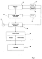
- FIG 3 there is shown a schematic and schematic table illustrating the operation of an information terminal according to the present invention.
- the detection of the angle ⁇ of the terminal with respect to its original position is performed at 30.
- the rotational speed is determined at 32, for example by deriving the angular position of the terminal in time.
- the rotational speed determines the implementation of the brake 34 to prevent deterioration of the assembly.
- the non-use time is calculated by the module 36 by means of the clock 38 of the microcomputer.
- This module 36 controls the return means 40 of the terminal so as to return it to its initial reference position, as well as the means for resetting the angular position 42, in other words "reset".
- the standby of the terminal can advantageously cause the start of a waiting program broadcast on the screen of the display means.
- the angular registration means executes its work transparently for the user.
- the microcomputer will look in an internal library 44, on the one hand the image corresponding to the angular position chosen by the user and information likely to be requested by the user. The image is then displayed at 46 on the aforementioned display means, with a list of possible questions. A "menu" waiting can advantageously then be displayed transparently or not.
- the display means is a speaker, it is not an image, but a sound.
- a public information terminal of this type offers many advantages to the user, since it is very easy to use and fun, and is perfectly suitable for use on premises. such as museums, fairs and exhibitions.
- the library of images and / or sounds will advantageously include only bare images, that is to say devoid of noise visitors, and / or pure sounds, that is to say devoid of noise. ambient, so as to restore the original setting of the space concerned.
- the terminal can then act as a virtual camera if there is screen.
- such a public information terminal can be arranged on a telescopic support means.
- the display terminal according to the invention can be provided with a motor means for assisting the rotation of the display means, this means for cooperating with the aforementioned brake means.
- Such motor means may be, favorably, a voice-controlled type of means for facilitating the use of the terminal according to the invention.
- a camera means may also be associated with the terminal so as to output a real image of the viewing area, before obtaining the image and the information stored in the memory of the microcomputer.
- the public information terminal displays on its screen or diffuses by a speaker pre-programmed information, when no user approaches.
- a proximity detector can favorably be provided in this case.
- the public information terminal according to the invention may also be removably mounted on wheels or equivalent. Such wheels may be removable or retractable if necessary.
- It may also include a touch screen and / or voice control means.
Landscapes
- Engineering & Computer Science (AREA)
- Physics & Mathematics (AREA)
- Theoretical Computer Science (AREA)
- General Physics & Mathematics (AREA)
- Mathematical Physics (AREA)
- Business, Economics & Management (AREA)
- Educational Administration (AREA)
- Educational Technology (AREA)
- User Interface Of Digital Computer (AREA)
- Position Input By Displaying (AREA)
- Devices For Indicating Variable Information By Combining Individual Elements (AREA)
- Controls And Circuits For Display Device (AREA)
Description
- La présente invention concerne une borne publique d'information, notamment pour milieu urbain, permettant de délivrer, de manière simple et intuitive, des informations concernant le monde environnant.
- Des bornes publiques d'information sont connues. Elles comportent généralement un moyen d'affichage de type écran pour délivrer l'information demandée. Elles requièrent, de façon générale, une interface de commande de la machine, telle qu'un clavier, un écran tactile ou équivalent. Dans certains cas, l'interface de commande est un casque pourvu d'une pluralité de capteurs et permettant de calculer l'orientation de la tête de l'utilisateur. Tous ces dispositifs sont soit techniquement extrêmement complexes, soit de peu d'efficacité, et, dans tous les cas, ils sont extrêmement rigides.
- L'interface de commande reste cependant peu engageante pour un utilisateur éventuel, puisque d'une manipulation sensiblement fastidieuse. De ce fait, l'utilisateur éventuel continue à s'adresser régulièrement à un service d'accueil.
- En outre, de telles bornes d'information ne délivrent qu'une information très limitée, par exemple un plan ou une carte, dont la lecture et la compréhension restent difficiles.
- Le document WO-A-93/09401 propose un lecteur informatique personnel et portable incluant un compas adapté pour mesurer l'angle entre l'orientation de l'appareil et le nord magnétique. Un écran permet de visualiser une carte ou équivalent en fonction de l'orientation du lecteur.
- Un tel lecteur présente de nombreux inconvénients, notamment en ce qui concerne son prix et son utilisation. Une caution préalable élevée doit être demandée à l'utilisateur occasionnel, et une grande précaution est également requise à ce dernier pour le transport et la manipulation.
- En outre, puisqu'il est destiné à une utilisation publique, un tel lecteur pose des problèmes d'hygiène du fait de ses utilisateurs successifs ; il pose également des problèmes de résistance dans le temps, puisqu'il est utilisé par des personnes non initiées.
- Par ailleurs, on connaît de WO-A-96/25702, un appareil portable de traitement de données qui affiche des graphismes modifiés en fonction de l'orientation spatiale de l'appareil. Un capteur commandé par gravité mesure en permanence l'orientation spatiale de l'appareil par rapport à l'horizontale de manière à commander le déplacement évolutif d'objets sur l'écran. Cet appareil reprend donc, sous forme électronique et coûteuse, un jeu ancien comportant des billes circulant dans un plan et devant être disposées simultanément dans des emplacements précis du plan.
- On connait également le document DE-U-296 14 277 qui décrit un centre d'informations constitué par un boîtier qui comprend au moins un écran et un clavier. Le boîtier peut être orienté verticalement ou horizontalement. Le boîtier renferme une unité de calcul commandant l'écran et le clavier. Le but de ce dispositif est de faciliter la lecture des informations que l'écran affiche. Le boîtier est donc rendu rotatif autour d'un axe vertical et/ou horizontal, de manière à éviter les réflexions sur l'écran. Par ailleurs, le fait que l'écran soit rotatif permet à un handicapé assis dans un fauteuil roulant qui ne peut se lever, ou à de petites personnes, par exemple des enfants, de lire facilement les informations affichées sur l'écran. La rotation de l'écran est commandée par l'ordinateur et non par l'utilisateur.
- Il existe donc un besoin d'une borne publique d'information qui soit simple d'utilisation pour tout utilisateur et efficace sans qu'il soit nécessaire d'adjoindre sur les lieux des dispositifs d'orientation additionnels, de type flèches, qui sont toujours malvenus et inesthétiques dans certains cadres tels que des musées.
- Il est également nécessaire qu'une telle borne d'information n'ait pas besoin d'être portée par l'utilisateur, ni qu'elle soit totalement individuelle. Elle doit, en outre, être ludique et de toute sécurité, tant pour le matériel que pour l'utilisateur.
- L'invention atteint ces buts au moyen d'une borne publique d'information comprenant, en combinaison :
- un micro-ordinateur dont le moyen d'interface sonore ou graphique est monté à rotation sur un moyen de support,
- un moyen de visée permettant d'orienter angulairement le moyen d'interface, et
- un moyen de programme.
- Selon l'invention, cette borne publique comprend, en outre, un moyen de détection et de mesure de la position angulaire du moyen d'interface et connecté au micro-ordinateur, le moyen de programme permettant d'exploiter la position angulaire du moyen d'interface pour délivrer une information correspondant à la position angulaire précitée.
- On a ainsi une borne d'information que l'utilisateur peut orienter à volonté et indépendante de la position de la tête de l'utilisateur. Ce dernier n'a, en outre, nullement besoin d'un mode d'emploi. Il lui suffit d'imprimer une rotation à la borne et de la diriger vers une direction souhaitée pour obtenir sur un écran ou sur un haut-parleur toute l'information souhaitée sur la direction donnée.
- Une telle borne d'information trouve donc son application dans tous les lieux publics, tels que les musées, les expositions, les points d'observation géographique, etc...
- De préférence, la borne d'information comprend, en outre, un moyen de rappel du moyen d'interface ramenant ce dernier vers une position initiale d'attente lors de la non-utilisation de la borne, et, si possible, un moyen de frein interdisant toute rotation brusque et rapide du moyen d'interface.
- De façon préférentielle, la borne publique d'information comprend, en outre, un moyen de recalage angulaire permettant de redéfinir périodiquement la position angulaire initiale du dispositif d'interface.
- De préférence également, la borne publique d'information selon l'invention est encore perfectionnée en montant le moyen d'interface à pivotement sur le moyen de support, le moyen de détection et de mesure mesurant, en outre, l'angle azimutal.
- L'invention sera mieux comprise, et d'autres buts, avantages et caractéristiques de celle-ci apparaîtront plus clairement à la lecture de la description qui suit des mode préférés de réalisation donnés à titre non limitatif et à laquelle deux planches de dessins sont annexées sur lesquelles :
- La Figure 1 illustre schématiquement le principe de la borne d'information selon l'invention vue de dessus ;
- La Figure 2 représente en perspective une borne d'information conformément à l'invention ; et
- La Figure 3 est un tableau synoptique et schématique du fonctionnement d'une telle borne d'information.
- En référence maintenant aux dessins, la borne publique d'information est symboliquement représentée sous la référence 10 sous une forme sensiblement d'un secteur dont l'arc courbe 12 constitue le moyen d'interface, c'est à dire soit un écran, soit un haut-parleur. Ci-après, il sera fait référence à un dispositif d'affichage sous forme générique pour désigner un écran ou un haut-parleur constituant ce moyen d'interface. La pointe 14 constituée par les deux segments rectilignes constitue un dispositif de visée symbolisé par la flèche 16. L'ensemble est monté à rotation autour d'un axe central 18 illustré par un référentiel orthogonal.
- Une rotation d'un angle a de l'élément rotatif de la borne d'information 10 peut être facilement détectée par tout moyen connu, par exemple une roue à crémaillère, un dispositif potentiométrique ou équivalent.
- Bien évidemment, quoique la Figure 1 illustre une vue de dessus d'une borne d'information mettant en relief la position angulaire du dispositif d'affichage dans un plan horizontal, il est clair qu'une rotation azimutale peut, de la même façon, être relevée et transmise au micro-ordinateur.
- Un mode de réalisation a été représenté en perspective sur la Figure 2. La borne publique d'information inclut un micro-ordinateur dissimulé à l'intérieur du moyen d'affichage 10. Ce moyen d'affichage 10 comporte un écran (et/ou un haut-parleur) 12. Le moyen d'affichage 10 est monté à rotation ou à pivotement sur un moyen de support, par exemple de type mât 20, ou sur un piètement conventionnel, monté sur un pied 22. Une poignée 24, par exemple circulaire ou partiellement circulaire, permet de manoeuvrer le moyen d'affichage en rotation. La pointe 14 du moyen d'affichage peut constituer un moyen de visée permettant d'orienter le moyen d'affichage 10.
- Bien que cela ne soit pas représenté sur les Figures, un moyen de rappel du moyen d'interface permet de ramener doucement ce dernier vers une position initiale de référence lorsque sa position n'a pas été modifiée pendant un certain temps. Ce moyen de rappel est, de préférence, constitué par un moteur électrique commandé par le micro-ordinateur lui-même, mais il peut alternativement être constitué par un moyen de ressort bandé par une rotation précédente, moyen de ressort comprenant un ressort spiralé ou un vérin à air comprimé. Un moyen de rappel magnétique peut également être envisagé.
- Bien évidemment, un moyen de butées est prévu pour limiter l'angle de rotation possible du moyen d'interface, notamment lorsque le moyen de rappel est un moyen mécanique. Toutefois un tel moyen de butées n'est pas nécessaire si le moyen d'interface peut effectuer une ou plusieurs rotations complètes. Dans un tel cas, il se pose un problème d'alimentation électrique de la borne, qui peut être résolu de façon classique.
- Egalement non représenté, un moyen de frein est prévu pour éviter toute rotation brusque, rapide ou intempestive du moyen d'interface de la borne d'information. Ce moyen de frein est généralement couplé au moyen de rappel précité.
- Lorsque le moyen de rappel a fonctionné pour remettre la borne dans sa position de référence initiale, ou bien lorsque la borne est mise en service, un moyen de recalage permet de redéfinir la position angulaire initiale de la borne et de mettre cette information en mémoire dans le micro-ordinateur.
- Sur la Figure 3, on a représenté un tableau synoptique et schématique illustrant le fonctionnement d'une borne d'information selon la présente invention.
- La détection de l'angle a de la borne par rapport à sa position d'origine est effectuée en 30. La vitesse de rotation est déterminée en 32, par exemple par dérivation de la position angulaire de la borne dans le temps. La vitesse de rotation détermine la mise en oeuvre du frein 34 pour éviter toute détérioration de l'ensemble.
- Ensuite, le temps de non-utilisation est calculé par le module 36 au moyen de l'horloge 38 du micro-ordinateur. Ce module 36 commande le moyen de rappel 40 de la borne de manière à la remettre en sa position initiale de référence, ainsi que le moyen de recalage de la position angulaire 42, autrement dit "remise à zéro". La mise en veille de la borne peut avantageusement provoquer la mise en route d'un programme d'attente diffusé sur l'écran du moyen d'affichage. Dans ce cas, le moyen de recalage angulaire exécute son oeuvre de façon transparente pour l'utilisateur.
- Lorsque tout est conforme, c'est à dire que la position angulaire du moyen d'interface de la borne est stabilisée, c'est à dire qu'elle n'est pas modifiée pendant un temps supérieur à un seuil déterminé, par exemple de l'ordre de une ou deux seconde(s), le micro-ordinateur va chercher dans une bibliothèque interne 44, d'une part l'image correspondant à la position angulaire choisie par l'utilisateur et les informations susceptibles d'être demandées par l'utilisateur. L'image est alors affichée en 46 sur le moyen d'affichage précité, avec une liste de questions possibles. Un "menu" d'attente peut avantageusement être alors affiché de façon transparente ou non. Bien évidemment, si le moyen d'affichage est un haut-parleur, il ne s'agit pas d'une image, mais d'un son.
- On aura compris qu'une borne publique d'information de ce type offre de nombreux avantages à l'utilisateur, puisqu'elle est très facile d'utilisation et ludique, et qu'elle est tout à fait appropriée à une utilisation sur des lieux publics tels que des musées, foires et expositions.
- En outre, la bibliothèque d'images et/ou de sons ne comprendra, de façon avantageuse, que des images nues, c'est à dire dépourvues de visiteurs parasites, et/ou de sons purs, c'est à dire dépourvus des bruits ambiants, de manière à restituer le cadre originel de l'espace concerné. La borne pourra alors agir en tant que caméra virtuelle s'il y a écran.
- Bien que l'on ait représenté et décrit ce que l'on considère actuellement être les modes de réalisation préférés de présente invention, il est évident que l'Homme de l'Art pourra y apporter différents changements et modifications sans sortir du cadre de la présente invention tel que défini ci-après.
- Par exemple, une telle borne publique d'information peut être disposée sur un moyen de support de type télescopique.
- Autre exemple, la borne d'affichage selon l'invention peut être pourvue d'un moyen moteur permettant une assistance à la rotation du moyen d'affichage, ce moyen permettant de coopérer avec le moyen de frein précité. Un tel moyen moteur peut être, favorablement, un moyen du type à commande vocale pour faciliter l'utilisation de la borne conforme à l'invention.
- Un moyen de caméra peut également être associé à la borne de manière à délivrer une image réelle de la zone de visée, avant d'obtenir l'image et les informations mémorisées dans la mémoire du micro-ordinateur.
- On pourra également prévoir que la borne publique d'information affiche sur son écran ou diffuse par un haut-parleur une information pré-programmée, lorsque aucun utilisateur ne s'en approche. Un détecteur de proximité peut favorablement être prévu dans ce cas.
- Bien évidemment, la borne publique d'information selon l'invention pourra également être montée de façon amovible sur roulettes ou équivalent. De telles roulettes pourront être amovibles ou rétractables si nécessaire.
- Elle pourra également comporter un écran tactile et/ou un moyen de commande vocale.
Claims (8)
- Borne publique d'information (10) comprenant, en combinaison :un micro-ordinateur dont le moyen d'interface sonore ou graphique (12) est monté à rotation sur un moyen de support (20, 22),un moyen de visée (14) permettant d'orienter angulairement le dit moyen d'interface (12), etun moyen de programme,
caractérisée en ce qu'elle comprend, en outre,
un moyen (30) de détection et de mesure de la position angulaire (a) du dit moyen d'interface (12) et connecté au dit micro-ordinateur, le dit moyen de programme permettant d'exploiter la position angulaire (a) du dit moyen d'interface (12) pour délivrer une information correspondant à la dite position angulaire (a). - Borne publique selon la revendication 1, caractérisée en ce qu'elle comprend, en outre, un moyen de rappel (40) du dit moyen d'interface (12) ramenant ce dernier vers une position initiale d'attente lors de la non-utilisation de la dite borne (10).
- Borne publique selon la revendication 1 ou 2, caractérisée en ce qu'elle comprend, en outre, un moyen de frein (34) interdisant toute rotation brusque et rapide du dit moyen d'interface (12).
- Borne publique selon l'une quelconque des revendications précédentes, caractérisée en ce qu'elle comprend, en outre, un moyen de recalage angulaire permettant de redéfinir périodiquement la position angulaire initiale (a) du dit dispositif d'interface (12).
- Borne publique selon l'une quelconqupe des revendications précédentes, caractérisée en ce que le dit moyen d'interface (12) est monté à pivotement sur le dit moyen de support (20, 22), le dit moyen de détection et de mesure (30) mesurant, en outre, l'angle azimutal.
- Borne publique selon l'une quelconque des revendications précédentes, caractérisée en ce qu'elle comprend, en outre, un moyen de butées limitant l'angle de rotation possible..
- Borne publique selon l'une quelconque des revendications précédentes, caractérisée en ce qu'elle comporte, en outre, un moyen moteur d'assistance à la rotation.
- Borne publique selon l'une quelconque des revendications précédentes, caractérisée en ce qu'elle comporte, en outre, un détecteur de proximité.
Applications Claiming Priority (3)
| Application Number | Priority Date | Filing Date | Title |
|---|---|---|---|
| FR9702977 | 1997-03-13 | ||
| FR9702977A FR2760863B1 (fr) | 1997-03-13 | 1997-03-13 | Borne publique d'information |
| PCT/FR1998/000512 WO1998040869A1 (fr) | 1997-03-13 | 1998-03-13 | Borne publique d'information |
Publications (2)
| Publication Number | Publication Date |
|---|---|
| EP1018103A1 EP1018103A1 (fr) | 2000-07-12 |
| EP1018103B1 true EP1018103B1 (fr) | 2006-02-22 |
Family
ID=9504688
Family Applications (1)
| Application Number | Title | Priority Date | Filing Date |
|---|---|---|---|
| EP98914912A Expired - Lifetime EP1018103B1 (fr) | 1997-03-13 | 1998-03-13 | Borne publique d'information |
Country Status (5)
| Country | Link |
|---|---|
| EP (1) | EP1018103B1 (fr) |
| DE (1) | DE69833547T2 (fr) |
| ES (1) | ES2259454T3 (fr) |
| FR (1) | FR2760863B1 (fr) |
| WO (1) | WO1998040869A1 (fr) |
Families Citing this family (6)
| Publication number | Priority date | Publication date | Assignee | Title |
|---|---|---|---|---|
| DE19719038C2 (de) * | 1997-04-30 | 2002-10-24 | Art & Com Medientechnologie Un | Vorrichtung und Verfahren und ihre Verwendung zur veränderbaren Darstellung |
| DE19734409C2 (de) * | 1997-08-08 | 1999-11-25 | Jeffrey Shaw | Orientierungsvorrichtung |
| DE10028713B4 (de) * | 2000-06-08 | 2010-11-25 | Art+Com Ag | Visualisierungsvorrichtung und -verfahren |
| DE202006008325U1 (de) * | 2006-05-05 | 2006-08-10 | Stumm-Tippe, Karin | Vorrichtung zur Darstellung von Bildinformation |
| CN105280120A (zh) * | 2014-06-25 | 2016-01-27 | 华北水利水电大学 | 一种平面设计电控动感展示装置 |
| FR3042900B1 (fr) * | 2016-04-01 | 2018-02-02 | Voog | Mobilier d'orientation pietonne ameliore |
Family Cites Families (5)
| Publication number | Priority date | Publication date | Assignee | Title |
|---|---|---|---|---|
| US4472025A (en) * | 1982-09-09 | 1984-09-18 | Huston Henry H | Visual orientation device |
| BE904513A (fr) * | 1986-03-28 | 1986-09-29 | Waudoit Claude | Table d'orientation et de localisation sur carte. |
| FR2683355A1 (fr) * | 1991-10-30 | 1993-05-07 | Bertrand Georges | Lecteur de cartes numerisees portable. |
| KR100404994B1 (ko) * | 1995-02-13 | 2004-02-11 | 코닌클리케 필립스 일렉트로닉스 엔.브이. | 스크린과스크린지향성을위해중력-제어된센서가제공되는휴대용데이터처리장치 |
| DE29614277U1 (de) * | 1996-08-17 | 1996-12-19 | Dorn, Guido, 87730 Grönenbach | Informationszentrum |
-
1997
- 1997-03-13 FR FR9702977A patent/FR2760863B1/fr not_active Expired - Fee Related
-
1998
- 1998-03-13 WO PCT/FR1998/000512 patent/WO1998040869A1/fr not_active Ceased
- 1998-03-13 EP EP98914912A patent/EP1018103B1/fr not_active Expired - Lifetime
- 1998-03-13 ES ES98914912T patent/ES2259454T3/es not_active Expired - Lifetime
- 1998-03-13 DE DE69833547T patent/DE69833547T2/de not_active Expired - Lifetime
Also Published As
| Publication number | Publication date |
|---|---|
| FR2760863A1 (fr) | 1998-09-18 |
| ES2259454T3 (es) | 2006-10-01 |
| EP1018103A1 (fr) | 2000-07-12 |
| FR2760863B1 (fr) | 1999-05-28 |
| DE69833547T2 (de) | 2006-12-21 |
| WO1998040869A1 (fr) | 1998-09-17 |
| DE69833547D1 (de) | 2006-04-27 |
Similar Documents
| Publication | Publication Date | Title |
|---|---|---|
| EP2364757B1 (fr) | Procédé et appareil de télécommande d'un drone, notamment d'un drone à voilure tournante | |
| DE69707302D1 (de) | Anzeige mit orientierungsabhängigem drehbarem bild | |
| CN113407291A (zh) | 内容项显示方法、装置、终端及计算机可读存储介质 | |
| EP1018103B1 (fr) | Borne publique d'information | |
| FR2889606A1 (fr) | Presentoir d'images photographiques numeriques | |
| FR3012933A1 (fr) | Camera de surveillance infrarouge | |
| EP1256085A1 (fr) | Systeme et procede de commande dans un environnement informatique | |
| FR3066834B1 (fr) | Procede d'assistance a l'installation d'au moins un occulteur reel pour un detecteur de presence et dispositif associe | |
| EP3602253A1 (fr) | Système de transparence pour caméra banalisée | |
| EP3172636B1 (fr) | Objet portable tactile ayant une extinction des touches tactiles simplifiee | |
| WO2011151437A1 (fr) | Support intelligent d'objet | |
| WO1994029748A1 (fr) | Dispositif de localisation a distance de sources de rayonnement | |
| FR2941791A1 (fr) | Dispositif de projection spherique interactive | |
| US6452571B1 (en) | Visual display system | |
| WO2005059780A1 (fr) | Dispositif et procedee de visualisation sur ecran video | |
| EP2943949A2 (fr) | Dispositif portable de lecture interactif et procédé d'affichage d'un document numérique sur ce dispositif | |
| FR2978942A1 (fr) | Procede et dispositif d'affichage pour vehicule, element de vehicule muni d'un tel dispositif et vehicule muni d'un tel element. | |
| FR3127597A1 (fr) | Systeme d’interface homme-machine | |
| WO2007042648A1 (fr) | Dispositif nomade de diffusion de contenus multimedia | |
| WO2022263786A1 (fr) | Dispositif optique pour afficher un contenu à proximité de l'œil d'un utilisateur | |
| WO2007135289A2 (fr) | Dispositif de commande à distance | |
| EP4409386A1 (fr) | Systeme d'interface homme-machine | |
| FR3160785A1 (fr) | Systeme de réalité etendue | |
| FR2818384A1 (fr) | Dispositif de controle des deplacements d'une structure | |
| CN113626127A (zh) | 内容项展示方法、装置、终端及存储介质 |
Legal Events
| Date | Code | Title | Description |
|---|---|---|---|
| PUAI | Public reference made under article 153(3) epc to a published international application that has entered the european phase |
Free format text: ORIGINAL CODE: 0009012 |
|
| AK | Designated contracting states |
Kind code of ref document: A1 Designated state(s): DE ES FR GB IT |
|
| 17P | Request for examination filed |
Effective date: 19991227 |
|
| 19U | Interruption of proceedings before grant |
Effective date: 20040820 |
|
| 19W | Proceedings resumed before grant after interruption of proceedings |
Effective date: 20041005 |
|
| GRAP | Despatch of communication of intention to grant a patent |
Free format text: ORIGINAL CODE: EPIDOSNIGR1 |
|
| GRAS | Grant fee paid |
Free format text: ORIGINAL CODE: EPIDOSNIGR3 |
|
| GRAA | (expected) grant |
Free format text: ORIGINAL CODE: 0009210 |
|
| GRAF | Information related to payment of grant fee modified |
Free format text: ORIGINAL CODE: EPIDOSCIGR3 |
|
| AK | Designated contracting states |
Kind code of ref document: B1 Designated state(s): DE ES FR GB IT |
|
| REG | Reference to a national code |
Ref country code: GB Ref legal event code: FG4D Free format text: NOT ENGLISH |
|
| REF | Corresponds to: |
Ref document number: 69833547 Country of ref document: DE Date of ref document: 20060427 Kind code of ref document: P |
|
| GBT | Gb: translation of ep patent filed (gb section 77(6)(a)/1977) |
Effective date: 20060531 |
|
| REG | Reference to a national code |
Ref country code: ES Ref legal event code: FG2A Ref document number: 2259454 Country of ref document: ES Kind code of ref document: T3 |
|
| PLBE | No opposition filed within time limit |
Free format text: ORIGINAL CODE: 0009261 |
|
| STAA | Information on the status of an ep patent application or granted ep patent |
Free format text: STATUS: NO OPPOSITION FILED WITHIN TIME LIMIT |
|
| 26N | No opposition filed |
Effective date: 20061123 |
|
| PGFP | Annual fee paid to national office [announced via postgrant information from national office to epo] |
Ref country code: ES Payment date: 20100921 Year of fee payment: 13 |
|
| PGFP | Annual fee paid to national office [announced via postgrant information from national office to epo] |
Ref country code: IT Payment date: 20100924 Year of fee payment: 13 |
|
| PGFP | Annual fee paid to national office [announced via postgrant information from national office to epo] |
Ref country code: DE Payment date: 20100922 Year of fee payment: 13 |
|
| PGFP | Annual fee paid to national office [announced via postgrant information from national office to epo] |
Ref country code: GB Payment date: 20110926 Year of fee payment: 14 |
|
| PG25 | Lapsed in a contracting state [announced via postgrant information from national office to epo] |
Ref country code: IT Free format text: LAPSE BECAUSE OF NON-PAYMENT OF DUE FEES Effective date: 20110313 |
|
| REG | Reference to a national code |
Ref country code: ES Ref legal event code: FD2A Effective date: 20120423 |
|
| PG25 | Lapsed in a contracting state [announced via postgrant information from national office to epo] |
Ref country code: ES Free format text: LAPSE BECAUSE OF NON-PAYMENT OF DUE FEES Effective date: 20110314 |
|
| GBPC | Gb: european patent ceased through non-payment of renewal fee |
Effective date: 20120313 |
|
| PG25 | Lapsed in a contracting state [announced via postgrant information from national office to epo] |
Ref country code: GB Free format text: LAPSE BECAUSE OF NON-PAYMENT OF DUE FEES Effective date: 20120313 |
|
| REG | Reference to a national code |
Ref country code: DE Ref legal event code: R119 Ref document number: 69833547 Country of ref document: DE Effective date: 20121002 |
|
| PGFP | Annual fee paid to national office [announced via postgrant information from national office to epo] |
Ref country code: FR Payment date: 20130426 Year of fee payment: 16 |
|
| PG25 | Lapsed in a contracting state [announced via postgrant information from national office to epo] |
Ref country code: DE Free format text: LAPSE BECAUSE OF NON-PAYMENT OF DUE FEES Effective date: 20121002 |
|
| REG | Reference to a national code |
Ref country code: FR Ref legal event code: ST Effective date: 20141128 |
|
| PG25 | Lapsed in a contracting state [announced via postgrant information from national office to epo] |
Ref country code: FR Free format text: LAPSE BECAUSE OF NON-PAYMENT OF DUE FEES Effective date: 20140331 |