EP1018206B1 - Module stator pour un moteur electrique - Google Patents
Module stator pour un moteur electrique Download PDFInfo
- Publication number
- EP1018206B1 EP1018206B1 EP99936500A EP99936500A EP1018206B1 EP 1018206 B1 EP1018206 B1 EP 1018206B1 EP 99936500 A EP99936500 A EP 99936500A EP 99936500 A EP99936500 A EP 99936500A EP 1018206 B1 EP1018206 B1 EP 1018206B1
- Authority
- EP
- European Patent Office
- Prior art keywords
- stator
- unit
- module according
- elements
- rotor
- Prior art date
- Legal status (The legal status is an assumption and is not a legal conclusion. Google has not performed a legal analysis and makes no representation as to the accuracy of the status listed.)
- Expired - Lifetime
Links
- 238000004804 winding Methods 0.000 claims abstract description 32
- 230000004907 flux Effects 0.000 claims abstract description 17
- 239000000463 material Substances 0.000 claims abstract description 12
- 238000004663 powder metallurgy Methods 0.000 claims abstract description 11
- 229910052751 metal Inorganic materials 0.000 claims description 9
- 230000008878 coupling Effects 0.000 claims description 8
- 238000010168 coupling process Methods 0.000 claims description 8
- 238000005859 coupling reaction Methods 0.000 claims description 8
- 239000007787 solid Substances 0.000 claims description 2
- 230000000295 complement effect Effects 0.000 claims 1
- 230000006835 compression Effects 0.000 claims 1
- 238000007906 compression Methods 0.000 claims 1
- XEEYBQQBJWHFJM-UHFFFAOYSA-N Iron Chemical group [Fe] XEEYBQQBJWHFJM-UHFFFAOYSA-N 0.000 abstract description 57
- 230000002093 peripheral effect Effects 0.000 abstract description 6
- 238000004519 manufacturing process Methods 0.000 description 13
- 150000001875 compounds Chemical class 0.000 description 12
- 238000004382 potting Methods 0.000 description 10
- 238000009434 installation Methods 0.000 description 9
- 230000008901 benefit Effects 0.000 description 8
- 229910052742 iron Inorganic materials 0.000 description 5
- 239000002184 metal Substances 0.000 description 5
- 239000000843 powder Substances 0.000 description 5
- 230000017525 heat dissipation Effects 0.000 description 4
- 238000005266 casting Methods 0.000 description 3
- 239000002131 composite material Substances 0.000 description 3
- 238000010276 construction Methods 0.000 description 3
- 239000000696 magnetic material Substances 0.000 description 3
- 239000012811 non-conductive material Substances 0.000 description 3
- 230000035699 permeability Effects 0.000 description 3
- 238000001266 bandaging Methods 0.000 description 2
- 230000000694 effects Effects 0.000 description 2
- 230000008030 elimination Effects 0.000 description 2
- 238000003379 elimination reaction Methods 0.000 description 2
- 239000011347 resin Substances 0.000 description 2
- 229920005989 resin Polymers 0.000 description 2
- 206010001497 Agitation Diseases 0.000 description 1
- 229910000976 Electrical steel Inorganic materials 0.000 description 1
- 229910052782 aluminium Inorganic materials 0.000 description 1
- XAGFODPZIPBFFR-UHFFFAOYSA-N aluminium Chemical compound [Al] XAGFODPZIPBFFR-UHFFFAOYSA-N 0.000 description 1
- 238000000137 annealing Methods 0.000 description 1
- 230000005540 biological transmission Effects 0.000 description 1
- 230000015572 biosynthetic process Effects 0.000 description 1
- 239000003795 chemical substances by application Substances 0.000 description 1
- 238000001816 cooling Methods 0.000 description 1
- 230000006866 deterioration Effects 0.000 description 1
- 238000001035 drying Methods 0.000 description 1
- 238000005538 encapsulation Methods 0.000 description 1
- 239000000284 extract Substances 0.000 description 1
- 238000003197 gene knockdown Methods 0.000 description 1
- 238000005470 impregnation Methods 0.000 description 1
- 238000003475 lamination Methods 0.000 description 1
- 239000007788 liquid Substances 0.000 description 1
- 238000000034 method Methods 0.000 description 1
- 239000003595 mist Substances 0.000 description 1
- 239000012256 powdered iron Substances 0.000 description 1
- 230000008569 process Effects 0.000 description 1
- 230000009467 reduction Effects 0.000 description 1
Images


Classifications
-
- H—ELECTRICITY
- H02—GENERATION; CONVERSION OR DISTRIBUTION OF ELECTRIC POWER
- H02K—DYNAMO-ELECTRIC MACHINES
- H02K21/00—Synchronous motors having permanent magnets; Synchronous generators having permanent magnets
- H02K21/12—Synchronous motors having permanent magnets; Synchronous generators having permanent magnets with stationary armatures and rotating magnets
- H02K21/125—Synchronous motors having permanent magnets; Synchronous generators having permanent magnets with stationary armatures and rotating magnets having an annular armature coil
-
- H—ELECTRICITY
- H02—GENERATION; CONVERSION OR DISTRIBUTION OF ELECTRIC POWER
- H02K—DYNAMO-ELECTRIC MACHINES
- H02K1/00—Details of the magnetic circuit
- H02K1/02—Details of the magnetic circuit characterised by the magnetic material
-
- H—ELECTRICITY
- H02—GENERATION; CONVERSION OR DISTRIBUTION OF ELECTRIC POWER
- H02K—DYNAMO-ELECTRIC MACHINES
- H02K1/00—Details of the magnetic circuit
- H02K1/06—Details of the magnetic circuit characterised by the shape, form or construction
- H02K1/12—Stationary parts of the magnetic circuit
-
- H—ELECTRICITY
- H02—GENERATION; CONVERSION OR DISTRIBUTION OF ELECTRIC POWER
- H02K—DYNAMO-ELECTRIC MACHINES
- H02K2201/00—Specific aspects not provided for in the other groups of this subclass relating to the magnetic circuits
- H02K2201/12—Transversal flux machines
Definitions
- the invention relates to a Statorbautician for an electrical machine, in particular an AC machine in the form of a transverse flux machine.
- the publication DE 39 04 516 C discloses a Statorbautician for an electrical machine, in particular a transverse flux machine with at least one, at least one armature winding stator carrying unit which is associated with a rotor in the mounting bearing to form a relative to the axis of symmetry of the electric machine arranged in the radial direction air gap , Furthermore, the stator unit comprises at least one inference element formed with a circumferentially extending circumferential surface and made of powder metallurgically produced and pressed material.
- the yoke element is associated with two soft iron units which can be formed from tooth elements, forming essentially U-shaped cross-sectional areas when viewed in the axial direction of the tooth elements, the tooth elements of the individual soft iron units forming the legs in the cross-sectional area.
- the invention is therefore based on the object, a Statorbauhow of the type mentioned for an alternator, in particular a transverse flux machine, further develop such that the disadvantages mentioned are avoided.
- the Statorbauhow should have a simple structural design, which ensures cost-effective production and easy installation. Deterioration of heat dissipation characteristics should be avoided.
- Statorbauticianen for electrical machines especially Transversalflußmaschinen, with at least one, an armature winding stator unit, which forms an air gap with a rotor in the installed position in the radial direction in axial direction, at least from an installation position in the circumferential direction annularly extending and preferably annularly designed yoke element and with this a structural unit formable tooth elements, performing executed.
- the annular yoke element is produced by powder metallurgy or manufactured from a powder metallurgically produced component.
- the tooth elements consist of a soft magnetic material or material.
- the toothed elements are coupled to the annular yoke element in such a way that, viewed in an axial section of the electrical machine, they describe a substantially U-shaped cross-sectional area together with the annular yoke element, wherein the two legs of the U-shaped cross section are each formed by the toothed elements .
- protrusions extending in the installed position towards the rotor are understood, which form flanks or flank surfaces in the peripheral direction, wherein the two circumferentially facing flanks of two adjacent tooth elements in the circumferential direction describe stator tooth gaps.
- a multiplicity of toothed elements which in axial section are located in the axial direction on a common diameter, relative to the axis of symmetry of the electrical machine, or which can be described on a projected basis on the axis of symmetry when projecting, form a so-called soft iron unit.
- the coupling of the yoke element is carried out with two soft iron units.
- star-shaped soft iron elements in the circumferential direction are designed such that these a plurality of individual, in the direction of Rotor have wegersharenden from the annular yoke element and the tooth elements descriptive projections.
- the arrangement of the teeth elements descriptive projections of the soft iron units in the circumferential direction is carried out according to the configuration of the rotor with a certain distance from each other.
- the projections forming the toothed elements are coupled, in particular radially connected, to the annular return element via a common basic body extending in the circumferential direction with which they preferably form a structural unit.
- the soft iron units are joined to the annular yoke element by means of a press connection.
- a press connection offers the advantage that due to the lack of pure material connection, there is no dependence of the operating time on the composite materials used.
- the specific configuration of the press connection can be done differently. The selection is at the discretion of the responsible specialist.
- the winding bearing stator unit of yoke element and soft iron units or toothed elements can be offered as a compact and preassembled basic unit and integrated into the Statorbauaji, in particular the stator housing.
- the number of components to be fixed against each other in the axial and radial directions is relatively low and the fixation already takes place on the basis of the execution of Statorbauaji.
- the armature winding is arranged between the soft iron units.
- the entire unit including the armature winding can be impregnated with an insulating agent, for example an insulating resin.
- the portion of the stator unit made of powder metallurgy material offers the advantage of isotropic, magnetic and electrical properties.
- this area is only required as a return area for the magnetic flux between the soft iron units or the tooth elements forming them.
- the conditional due to the material properties worse permeability in this area can be taken into account because of the relative to the tooth elements enlarged flow cross-section.
- annular yoke member in the manner described provides the advantage of providing a compact stator component with improved strength, easy to manufacture, and having optimum electrical and magnetic properties.
- the soft iron units or the toothed elements forming them are laminations stacked in the axial direction, which, when viewed in the installed position, comprise in axial section successively piled-up annular elements of correspondingly punched sheet metal.
- each individual annular sheet metal element and thus each laminated core in the region of the peripheral surface oriented towards the rotor has edge-open recesses for the formation of the projections describing the toothed elements. This open-edged recesses are arranged distributed over the circumference of each annularly shaped sheet-metal element and thus also Belchfeles at equal intervals.
- each laminated core Viewed in the circumferential direction in the installation position describe the annular shaped sheet metal elements and thus each laminated core a substantially star-shaped contour.
- the number of installation positions in the axial direction successively arranged or stacked annular single sheet metal elements depends on the design of the entire electric machine.
- the representation of the soft iron elements as laminated cores ensures good permeability in the tooth area and minimizes the eddy current losses that occur.
- the armature winding stator unit in particular the stator part, is formed by the inner stator of a transverse flux machine.
- This offers the advantage of screwing the inner stator or at least the stator unit associated with a pole structure of the rotor into the stator housing as a completely pre-assembled assembly of annular yoke element and the toothed elements forming the soft iron units.
- the rotor In symmetrically constructed transversal flux machines, the rotor generally has two pole structures which extend away from a central carrier disk and belong to one electrical phase each. Accordingly, each pole structure should also be assigned to the corresponding stator units.
- the total structural unit stator in this case comprises at least two stator units designed according to the invention, which function as an inner stator and are assigned to the rotor, in particular the pole structures, on both sides of the carrier disk.
- the connection between the stator housing and inner stator takes place in the region of the annular yoke element, since this can be easily realized in this area without much effort.
- Conceivable are embodiments of Transversalflußmaschinen with two armature winding bearing stator units, which are assigned in the radial direction on both sides of a pole structure and in which the outer stator is also prefabricated as a preassembled unit in the manner described.
- Another third possibility is to execute only the outer stator as the armature winding bearing component.
- the outer stator is preferably made of a plurality of individual stator elements, which are made as a solid profile components made of powder metallurgy and pressed materials, which can be attached with simple fasteners directly to the stator.
- the attachment takes place by means of screw elements.
- simple as possible and easy to assemble full parts which can be used as standard in differently designed machines, they have in the region of their contact surface with the inner surface of the housing 5 from a substantially flat stop surface. Accordingly, preferably in the installed position facing the rotor end face of the housing is also designed with running in the axial direction just executed stop surfaces.
- To guide the connecting elements are passage openings on the housing 5, which can be provided with a thread and provided threads in the stator elements.
- the inventive design of the armature winding bearing stator unit offers in addition to a number of cost and manufacturing advantages also considerable functional advantages.
- the configuration of an inner stator core implemented in combination with the simplified configuration of the outer stator enables improved heat dissipation into the water-cooled stator housing.
- the armature winding can be cooled directly, for example when cooling by oil rotation generated by rotor rotation.
- an increase in the permissible continuous power to be expected by about 25% since the maximum permissible temperature during operation is no longer limited by the potting compound.
- the stator housing itself can be constructed very simply structured, in particular slots for a recording of cut cores are no longer necessary.
- required winding and impregnating devices for armature coil production account for and the means for bandaging the same.
- the hitherto complex assembly of the outer cut cores with Befest Trentsklammem reduced to simple screwing of soft magnetic material existing powder elements.
- the inventively designed stator - regardless of whether designed as an external or internal stator - can be supplied as a pre-assembled finished unit. An earlier required encapsulation of the armature coil and the Thomasbandkerne in the stator can be omitted, whereby the necessary subsequent rework can be avoided. Furthermore, it requires for the production of the individual elements and the assembly no complicated tools and no special know-how of entrusted employees.
- Fig. 1 illustrates by means of a section of an axial section of an electric machine 1 in the form of a transverse flux the structure of a stator configured according to the invention 2.
- the Statorbautician 2 has at least one, at least one armature winding 3 supporting stator 4.
- the stator winding 4 carrying the armature winding 3 is embodied here as an element of the overall unit of internal stator.
- the stator unit 4 is arranged in a stator housing 5.
- the Statorbautician 2 comprises an inner stator of two stator units, wherein representative only extracts for clarity only one of a pole structure of the rotor associated stator is shown.
- housing 5 a rotor 6 of the electric machine 1 is rotatably mounted.
- the rotor consists in a known manner of a central support plate 7, at the radially outer end portion symmetrically on both sides coaxial with the axis of rotation or rotation axis R of the rotor 6, which also acts as the axis of symmetry of the electric machine, for example, two pole structures, the pole structure 8.1 and here not shown on one side of the pole structure 8.2 are arranged.
- These pole structures each comprise permanent magnets 9.1.1 - 9.1 n and 9.2.1 - 9.2n, which are mutually polarized adjacent to each other in two rows in the circumferential direction and rotor magnet elements 10.1.1 - 10.1 n and 10.2.1 - 10.2n are arranged adjacent.
- the two rings are labeled 11 and 12 here.
- the rings of the alternately arranged circumferentially one behind the other permanent magnet 9 and the rotor soft iron elements 10 are by annular intermediate elements of magnetic and electrical non-conductive material separated from each other.
- this is at least the ring 13.
- the carrier disc and an axially limiting the pole structure end piece 14 are made of electrically and magnetically non-conductive material.
- plastic is used for this purpose.
- the pole structure 8.1 is separated from the stator unit 4 by an air gap 15.
- the stator unit 4 forms the radially inner inner stator or the part of the total structural unit associated with the pole structure 8.1.
- the stator 4 describes in a view in axial section of the electric machine of FIG. 1, a substantially U-shaped cross-sectional area.
- the stator unit 4 comprises at least one annular yoke element 16, which forms a structural unit with two soft iron units 17 and 18 formed from a plurality of tooth elements.
- the term soft iron units stands for elements made of soft magnetic materials.
- the soft iron units 17 and 18 are constructed such that they form in cross-section in axial section according to FIG. 1, two legs of the stator 4. These are designated 19 and 20 here.
- the legs 19 and 20 face the permanent magnet 9 of the pole structure 8.1 of the rotor 6, in particular the leg 20 the magnet 9.1.1 - 9.1 n and the leg 19 the magnet 9.2.1 - 9.2n.
- Within the legs 19 and 20 is located on three sides enclosed in the circumferential direction armature winding 3.
- the soft iron units 17 and 18 are circumferentially as shown in FIG. 3 designed such that these in the circumferential direction at the air gap 15 and the rotor 6 aligned peripheral surface 21.1 or 21.2 in General ceremonietemente 21.1.1 - 21.1 n or 21.2.1 - 21.2n are divided, which are spaced apart in the circumferential direction with a pitch in the specific ratio to the pole pitch T on the rotor.
- the soft iron units 17 and 18 are designed in the form of annular elements.
- the soft iron units 17 and 18 as axially stacked laminated cores executed.
- Each soft iron unit of a stator unit comprises a plurality of stamped annular elements of sheet metal plates arranged one behind the other in the axial direction.
- the spacing of the outer surfaces 2.1.1 - 21.1 n and 21.2.1 - 21.2n with a certain pitch to each other is realized by execution or training edge-open slots 22.1.1 to 22.1 n and 22.2.1 to 22.2n.
- the open-edged slots 22.1.1 - 22.1n and 22.2.1 - 22.2n extend from the area of the outer circumference 21.1 or 21.2 in the radial direction to the rotor 6 facing surface of the annular member 16.
- the open-edged slots are further in the axial direction coaxial with the axis of rotation R of the rotor.
- the openings always point towards the air gap or rotor 6.
- At least the annular element 16 is manufactured by powder metallurgy.
- the base material used is a metal powder.
- the powders are then pressed into so-called green bodies. These are pressed either cold or under elevated temperature to achieve certain properties. It can be done aftertreatment.
- the soft iron units 17 and 18 formed in each case from individual tooth elements have at least two partial regions in the radial direction, a first partial region 24.1 or 24.2 and a second partial region 25.1 or 25.2.
- the first portion 24.1 and 24.2 is provided for coupling with the annular yoke element 16 and also designed as an annular element.
- the coupling with the annular yoke element 16 takes place in the area facing away from the rotor 6 in installation position end face 26 of the soft iron unit 17 and 27 of the soft iron unit 18.
- the second portion 25.1 and 25.2 is formed from a plurality of single-tooth descriptive projections, which with 28.1.1 - 28.1 n are designated for the soft iron unit 17 and are preferably spaced in the circumferential direction with a certain pole pitch with respect to the arrangement of the permanent magnets on the rotor spaced.
- the single tooth elements 28.1.1 - 28.1 n are at Execution of the soft iron units of stamped sheet metal elements designed as a structural unit with the first portion 24.1.
- the individual teeth 28.1.1 - 28.1 n to 28.2.1 - 28.2n are then formed as projections.
- the soft iron units 17 and 18 which functions in the functional state as a so-called yoke ring and mechanically performs the function of a support member
- a non-positive coupling is made between the annular element 16 and the individual elements of the soft iron unit 17 formed from a plurality of toothed elements.
- This can be done in the simplest case by a press connection.
- the individual elements of the stator 4, annular yoke element 16 and the soft iron units 17 and 18 are interpreted in terms of their dimensions so that they enter into a specific fit with each other.
- the armature winding 3 which is arranged between the two legs 20 and 19 formed by the soft iron units 17 and 18 respectively, is wound directly onto the area of the end face 31 of the annular element 16 which is free of the partial surfaces 30.1 and 30.2.
- the armature winding 3 is fixed in the axial direction.
- the fixation in the radial direction results in the embodiment of the inner stator as a winding-carrying stator by the tension generated during winding.
- the armature winding 3 lies directly on the partial surface 33 of the end face 31 of the annular yoke element 16 which is oriented towards the rotor.
- the annular return element is preferably subdivided into three sections, a first section 35, a second section 36 and a third section 37.
- the section 36 forms in each case with the sections 35 and the sections 37 in the axial direction of a stop 38 for the soft iron unit 17 and a stop 39 for the soft iron unit 18.
- the sub-element 35 carries the sub-area 30.1, the sub-element 37, the sub-area 30.2, while the sub-element 36 carries the sub-area 33.
- the individual partial surfaces 30.1, 30.2 or 33 and thus the partial elements 35, 37 and 36 are formed by forming the annular element with different outer diameter.
- the embodiment of the inner stator in the cross-section corresponding to FIG. 1 thus differs in no way from the already known from the prior art stator in this view.
- the magnetic flux guide is also the same.
- the venezstatorbautician 4 which consists of the annular member 16, the soft iron units 17 and 18 and the armature winding can be provided as a completely pre-assembled unit.
- additional connecting elements for clamping the Statorbautician 4 are provided in the axial direction.
- a connecting element 40 which is a first stop member 41, which is assigned to the soft iron unit 18 in the axial direction and limits its mobility in the axial direction, with a second stop member 42 which is associated with the other soft iron unit 17, positively and non-positively coupled together or connects.
- the connecting element 40 extends through the soft iron units 18 and 17 and partly the annular yoke element 16, in particular in the region of the second partial element 36. The axial clamping takes place with the torque required on the inner stator or the stator 4 bias.
- Figures 1 to 3 illustrate the inventive design of the winding-carrying stator unit using the example of a section of an inner stator of a Transversalflußmaschine.
- This embodiment represents a preferred application of the inventive concept, but should not be limited to the embodiment as an inner stator.
- the embodiment according to the basic concept of the invention for the external stator is also conceivable.
- the solution described above is only applied to the inner stator, since the execution as an external stator in the circumferential direction has larger pole gaps and in turn cause increased losses, resulting in a Reduction of the overall efficiency of the electric machine 1 knock down.
- the stator housing 5 is mounted, for example via a bearing assembly 43 on the rotor shaft 44 of the rotor 6.
- the stator housing 5 has a radially extending end wall 46 and an axially extending annular housing member 47, which together form a structural unit.
- stator housing 5 in at least two-part design, wherein the radially extending end wall 46 and the annular housing member 47 form a structural unit and viewed at least in the axial direction in installation position extend over a region which extends through the radial axis of symmetry S R of the rotor 6 and the front-side element 14 can be described.
- the stator housing 5 consisting of the end wall 46 and the axially extending housing part 47, is designed as an integral component.
- the annular element of the stator 4 is fixed by means of at least one fastening element 48 on the stator housing 5, in particular of the end wall 46 extending in the radial direction.
- a plurality of fastening elements 48 are provided, which are arranged on a diameter d and viewed in the circumferential direction of the stator 5 are preferably arranged at equal distances from each other.
- the installation of the stator 4 is carried out as a preassembled module from the soft iron units 17, 18 and the annular yoke element 16, which is manufactured by powder metallurgy.
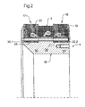
- FIG. 2 illustrates with reference to a detail of FIG. 1 in an enlarged view again the inner stator in the form of the stator 4. For the same elements, therefore, the same reference numerals are used.
- FIG. 2 shows the preassembled stator unit 4, as it can be used for installation in the stator housing 5, again.
- the inner stator itself or the stator unit 4 can be soaked after winding the armature coil 3 with an insulating resin and screwed into the stator housing 5 after drying.
- the stator assembly 1 typically further includes at least one second stator unit 50 which functions as an external stator.
- the stator unit 50 comprises a multiplicity of stator individual elements 51 which are arranged one behind the other in the circumferential direction and, in the axial section according to FIG. 1, also have a substantially U-shaped cross section.
- the stator elements 51 form an air gap 55 with the outer surface 54 of the rotor 6 in the installed position or in the mounted state of the electric machine 1.
- the stator unit 50 is preferably free of an armature winding.
- each Statoreinzelelement 51 Viewed in the circumferential direction in the installed position, each Statoreinzelelement a certain extent a.
- the Statoreinzelelement 51 is designed as an element with widened spine, which is preferably produced by powder metallurgy and pressed one piece.
- the individual stator elements 51 which are designed as a full part, are preferably connected to one another only by positive and non-positive connection means 56.1 to 56.N or 57.1 to 57.N. This connection preferably takes place by means of screw connections.
- the screw connections are guided by the outer surface 58 of the annular housing part 47 through the housing wall 49 of the annular housing part 47 and with corresponding counter elements in the Statoreinzelmaschinen 51 in Active compound brought.
- each Statoreinzelelement 51 has at least one incorporated into this thread. The thread extends from the outer surface directed away from the rotor in the direction of the rotor 6.
- Other connections that can be easily realized are likewise conceivable.
- both the stator individual elements 51 of the stator unit 50 and the annular yoke element 16 of the stator unit 4 are made of the same material.
- a powdered iron composite material is used.
- the powder metallurgy produced elements are independent of direction in terms of electrical and magnetic properties. Although these have a lower permeability compared to the components usually used from electrical steel, but this is not negative in the case of the stator construction preferably carried out in FIG. 1. The magnetic flux is still transversely guided.
- the ring-shaped return element has at least one circumferential outer surface.
- the inner contour is not bound to the annular design and can be designed in many forms. Also conceivable is the subdivision of the return element in the circumferential direction in at least two sub-elements which are plugged together in the mounting position or describe by the attachment to the stator housing the annular element in the circumferential direction, wherein at least one interruption can be provided in the circumferential direction.
- the inventive design has in its entirety significant cost, manufacturing and functional advantages. Since the stator housing itself must be designed without slots for the known in the prior art cut strip cores, this can be very easily, for example, as a casting produced. Additional winding and impregnating devices for the Coil production omitted as well as a bandaging derselbigen. Furthermore, the mounting of the stator on the outer stator designed much easier, since the complex assembly of outer cut cores can be omitted with mounting brackets. The inner cut cores are the same. Only the inner stator is only screwed in with the armature coil as a complete unit. A casting of the coil and the Thomasbandkerne in the stator can be omitted, as well as the subsequent evacuation and reworking and annealing of the potting compound.
Landscapes
- Engineering & Computer Science (AREA)
- Power Engineering (AREA)
- Iron Core Of Rotating Electric Machines (AREA)
- Motor Or Generator Frames (AREA)
- Insulation, Fastening Of Motor, Generator Windings (AREA)
Claims (17)
- Unité de stator (2) pour un moteur électrique, en particulier un moteur à flux transversal,
avec au moins une unité de stator (4) portant au moins un enroulement d'induit (3), qui est associée dans la position de montage à un rotor (6) en formant un entrefer (15, 55) disposé dans le sens radial par rapport à l'axe de symétrie du moteur électrique (1) ;
l'unité de stator (4) comprend au moins un élément de retour magnétique (16) doté d'une surface de circonférence (30.1, 30.2, 33) orientée dans le sens de la circonférence et fabriqué en matériau produit par métallurgie des poudres et compressé ;
l'élément de retour magnétique (16) est associé à deux unités en fer doux (17, 18) pouvant être composées à l'aide d'éléments en forme de dents (28.1.1-28.1.n ; 28.2.1-28.2.n) en formant des surfaces de section sensiblement en forme de U en coupe axiale au niveau des éléments en forme de dents (28.1.1-28.1.n ; 28.2.1-28.2.n), les éléments en forme de dents des différentes unités en fer doux (17, 18) formant les bras (19, 20) des surfaces de section ;
la position de l'enroulement d'induit (3) est limitée par la surface de circonférence (30.1, 30.2, 33) de l'élément de retour magnétique (16) orientée vers le rotor (6) et par les faces d'extrémité orientées l'une vers l'autre des unités de fer doux (17, 18);
caractérisée en ce que :l'élément de retour magnétique (16) comprend au moins trois segments (35, 36, 37), un premier segment (35), un deuxième segment (36) et un troisième segment (37) ;les deux unités de fer doux (17, 18) sont associées l'une au premier segment (35) et l'autre au troisième (37) et l'enroulement d'induit (3) au deuxième segment (36) ;le deuxième segment (36) au moins possède un diamètre extérieur différent du premier segment (35) et du troisième (37) et formant au moins une surface de butée (38, 39) dans le sens axial pour chaque unité en fer doux (17, 18) ;chaque unité en fer doux (17, 18) est associée en outre à une plaque d'extrémité (41, 42) pour limiter la mobilité dans le sens axial, avec des moyens (40) pour produire un serrage des éléments de l'unité en fer doux (17, 18), de l'élément de retour magnétique (16) et de la plaque d'extrémité (41, 42) dans le sens axial. - Unité de stator selon la revendication 1, caractérisée en ce que chaque unité en fer doux (17, 18) conformée comme un élément annulaire présente dans le sens de la circonférence, à des intervalles prédéfinis, des évidements ouverts sur le bord (22.1.1-22.1.n ; 22.2.1-22.2.n) sur les surfaces (21.1, 21.2) qui s'écartent de la circonférence annulaire (30.1, 30.2, 33) de l'élément de retour magnétique (16) en formant les éléments en forme de dents (21.1.1-21.1.n ; 21.2.1-21.2.n).
- Unité de stator selon l'une des revendications 1 ou 2, caractérisée en ce que l'élément de retour magnétique (16) et les unités de fer doux (17, 18) sont couplés ensemble par engagement positif.
- Unité de stator selon l'une des revendications 1 à 3, caractérisée en ce que l'élément de retour magnétique (16) et les unités de fer doux (17, 18) sont couplés ensemble par friction.
- Unité de stator selon la revendication 4, caractérisée en ce que le couplage par friction est réalisé par un assemblage fretté.
- Unité de stator selon l'une des revendications 1 à 5, caractérisée en ce que chaque unité en fer doux (17, 18) comprend une pluralité d'éléments en tôle qui sont disposés, vus en coupe axiale dans la position de montage, en empilement les uns derrière les autres de façon à former un paquet de tôles.
- Unité de stator selon la revendication 6, caractérisée en ce que :chaque paquet de tôles a une forme annulaire ;chaque paquet de tôles possède un corps orienté dans le sens de la circonférence avec des saillies (28.1.1-28.1.n ; 28.2.1-28.2.n) formées par des évidements ouverts sur le bord (22.1.1-22.1.n ; 22.2.1-22.2.n) au niveau de la surface de circonférence (21.1, 21.2) orientée vers le rotor (6) dans la position de montage ;les évidements ouverts sur le bord (22.1.1-22.1.n ; 22.2.1-22.2.n) et les saillies (28.1.1-28.1.n ; 28.2.1-28.2.n) sont disposés, vus dans le sens de la circonférence, à certains intervalles réguliers.
- Unité de stator selon l'une des revendications 1 à 7, caractérisée en ce que l'élément de retour magnétique (16) est construit en plusieurs parties.
- Unité de stator selon l'une des revendications 1 à 8, caractérisée en ce que l'unité de stator (4) est un élément du stator interne d'un moteur électrique (1).
- Unité de stator selon l'une des revendications 1 à 9, caractérisée en ce que l'unité de stator (4) est un élément du stator externe d'un moteur électrique (1).
- Unité de stator (2) selon l'une des revendications 1 à 10, caractérisée en ce qu'elle comporte les éléments suivants :un boîtier de stator (5) ;l'unité de stator (4) peut être reliée au boîtier de stator (5) au niveau de l'élément de retour magnétique (16).
- Unité de stator selon la revendication 11, caractérisée en ce que :le boîtier de stator (5) comprend au moins une partie de boîtier (47) orientée dans le sens de la circonférence et renfermant le rotor (6) ou le stator externe (50), pouvant être couplée avec une partie latérale (46) du côté de la face d'extrémité qui s'étend dans le sens radial.
- Unité de stator selon la revendication 12, caractérisée en ce que la partie annulaire du boîtier de stator (47) et la partie de boîtier disposée sur la face d'extrémité (46) forment un ensemble constructif.
- Unité de stator selon l'une des revendications 1 à 9 et 11 à 13, caractérisée en ce que :l'unité de stator (4) est réalisée comme un élément du stator interne ;le stator externe associé au rotor (6) en formant un entrefer (55) dans le sens radial comprend, dans le sens de la circonférence, plusieurs éléments pleins disposés à intervalles définis les uns par rapport aux autres et ayant une section en forme de U, avec des éléments en forme de dents (51) qui sont associés au rotor (6) de manière complémentaire comme les unités de stator (4) ;les éléments (51) sont faits de matériaux produits par métallurgie des poudres et compressés et sont reliés au moyen d'éléments de fixation (56.1-56.n ; 57.1-57.n) au boîtier du stator (5).
- Unité de stator selon la revendication 14, caractérisée en ce que l'assemblage entre les éléments (51) du stator externe et le boîtier du stator (5) est réalisé par des vissages.
- Unité de stator selon l'une des revendications 1 à 15, caractérisée en ce que chaque phase ou structure polaire (8.1, 8.2) du rotor (6) est associée à des unités de stator (4) de conformation identique.
- Unité de stator selon l'une des revendications 1 à 16, caractérisée en ce que les unités de fer doux (17, 18) sont partagées dans le sens de la circonférence.
Applications Claiming Priority (5)
| Application Number | Priority Date | Filing Date | Title |
|---|---|---|---|
| DE19833021 | 1998-07-23 | ||
| DE29813023U DE29813023U1 (de) | 1998-07-23 | 1998-07-23 | TFM-Stator mit eingeschraubten Weicheisenelementen |
| DE1998133021 DE19833021A1 (de) | 1998-07-23 | 1998-07-23 | Statorbaueinheit für eine elektrische Maschine |
| DE29813023U | 1998-07-23 | ||
| PCT/EP1999/004807 WO2000005804A1 (fr) | 1998-07-23 | 1999-07-08 | Module stator pour un moteur electrique |
Publications (3)
| Publication Number | Publication Date |
|---|---|
| EP1018206A1 EP1018206A1 (fr) | 2000-07-12 |
| EP1018206B1 true EP1018206B1 (fr) | 2006-12-27 |
| EP1018206B8 EP1018206B8 (fr) | 2007-03-07 |
Family
ID=26047617
Family Applications (1)
| Application Number | Title | Priority Date | Filing Date |
|---|---|---|---|
| EP99936500A Expired - Lifetime EP1018206B8 (fr) | 1998-07-23 | 1999-07-08 | Module stator pour un moteur electrique |
Country Status (5)
| Country | Link |
|---|---|
| US (1) | US6365999B1 (fr) |
| EP (1) | EP1018206B8 (fr) |
| AT (1) | ATE349798T1 (fr) |
| DE (1) | DE59914089D1 (fr) |
| WO (1) | WO2000005804A1 (fr) |
Cited By (1)
| Publication number | Priority date | Publication date | Assignee | Title |
|---|---|---|---|---|
| CN111404290A (zh) * | 2020-03-12 | 2020-07-10 | 华中科技大学 | 一种集中绕组横向磁通永磁同步电机 |
Families Citing this family (17)
| Publication number | Priority date | Publication date | Assignee | Title |
|---|---|---|---|---|
| DE10053589A1 (de) * | 2000-10-27 | 2002-05-29 | Voith Turbo Kg | Rotor für eine elektrische Maschine, insbesondere Synchronmaschine und Synchronmaschine mit transversaler Flußführung |
| CN1230620C (zh) * | 2001-03-24 | 2005-12-07 | Lg电子株式会社 | 往复式压缩机 |
| DE10145447A1 (de) * | 2001-09-14 | 2003-04-03 | Voith Turbo Kg | Verfahren zur Kühlung einer Synchronmaschine mit transversaler Flußführung und Synchronmaschine mit transversaler Flußführung |
| DE10145820A1 (de) * | 2001-09-17 | 2003-04-30 | Voith Turbo Kg | Rotor für eine Synchronmaschine mit transversaler Flussführung und Verfahren zur Verbesserung des Korrosionsschutzes |
| GB0329290D0 (en) * | 2003-12-17 | 2004-01-21 | Rolls Royce Plc | Stator coil assembly |
| US20060091755A1 (en) * | 2004-10-28 | 2006-05-04 | Precise Automation, Llc | Transverse flux switched reluctance motor and control methods |
| US7973446B2 (en) * | 2007-05-09 | 2011-07-05 | Motor Excellence, Llc | Electrical devices having tape wound core laminate rotor or stator elements |
| WO2008141214A1 (fr) * | 2007-05-09 | 2008-11-20 | Motor Excellence, Llc. | Dispositifs de génération de sortie électriques et dispositifs électriques d'entraînement avec une fuite de flux réduite utilisant des composants formant aimant permanent, et leurs procédés de fabrication et d'utilisation |
| EP2342803A2 (fr) | 2008-11-03 | 2011-07-13 | Motor Excellence, LLC | Concepts de rotor de système d écoulement transversal et/ou commuté |
| WO2011115632A1 (fr) | 2010-03-15 | 2011-09-22 | Motor Excellence Llc | Systèmes à flux transversal et/ou à flux commuté, configurés de façon à réduire les déperditions de flux, à réduire les déperditions d'hystérésis et à réaliser une adaptation de phase |
| WO2011115633A1 (fr) | 2010-03-15 | 2011-09-22 | Motor Excellence Llc | Systèmes à flux transversal et/ou à flux commuté pour vélos électriques |
| WO2011115634A1 (fr) | 2010-03-15 | 2011-09-22 | Motor Excellence Llc | Systèmes à flux transversal et/ou à flux commuté comprenant une caractéristique de décalage de phase |
| US8952590B2 (en) | 2010-11-17 | 2015-02-10 | Electric Torque Machines Inc | Transverse and/or commutated flux systems having laminated and powdered metal portions |
| CN103477538A (zh) | 2010-11-17 | 2013-12-25 | 电动转矩机器公司 | 具有分段定子层压件的横向和/或换向磁通系统 |
| US8854171B2 (en) | 2010-11-17 | 2014-10-07 | Electric Torque Machines Inc. | Transverse and/or commutated flux system coil concepts |
| US10193427B2 (en) | 2015-12-01 | 2019-01-29 | General Electric Company | Method of fabricating electric machine laminations using additive manufacturing |
| US11527944B2 (en) | 2015-12-07 | 2022-12-13 | General Electric Company | Additive manufacturing for segmented electric machines |
Family Cites Families (15)
| Publication number | Priority date | Publication date | Assignee | Title |
|---|---|---|---|---|
| US4620139A (en) * | 1985-07-22 | 1986-10-28 | Kabushiki Kaisha Shicoh Giken | Brushless d.c. motor |
| DE3536538A1 (de) | 1985-10-12 | 1987-04-23 | Weh Herbert | Transversalfluss-maschine mit permanenterregung |
| DE3705089A1 (de) | 1987-02-13 | 1988-08-25 | Weh Herbert | Transversalflussmaschine in sammleranordnung |
| US4959578A (en) * | 1987-11-24 | 1990-09-25 | Axial Electric, Inc. | Dual rotor axial air gap induction motor |
| DE3821660C1 (en) * | 1988-06-27 | 1989-08-10 | Robert Bosch Gmbh, 7000 Stuttgart, De | Reluctance machine |
| DE3904516C1 (fr) * | 1989-02-15 | 1990-06-13 | Robert Bosch Gmbh, 7000 Stuttgart, De | |
| DE3914635C1 (fr) | 1989-05-03 | 1990-08-02 | Robert Bosch Gmbh, 7000 Stuttgart, De | |
| US5592039A (en) * | 1990-07-23 | 1997-01-07 | Westinghouse Electric Corporation | AC and DC motor-generator set having stators with annular end plate water cooling channels |
| DE4034703A1 (de) | 1990-10-31 | 1992-05-14 | Magnet Motor Gmbh | Rotatorischer elektromotor |
| DE4314513C2 (de) * | 1993-05-03 | 1995-11-16 | Weh Herbert | Transversalflußmaschine mit kombinierter Permanentmagnet-Erregung |
| DE4328774A1 (de) | 1993-08-26 | 1995-03-02 | Voith Gmbh J M | Magnetanordnung für eine elektrische Maschine |
| ATE166500T1 (de) * | 1994-11-10 | 1998-06-15 | Voith Turbo Kg | Transversalflussmaschine |
| DE19610754C1 (de) * | 1996-03-19 | 1997-03-27 | Voith Turbo Kg | Rotor für eine elektrische Maschine, insbesondere Transversalflußmaschine |
| US6140726A (en) * | 1997-07-03 | 2000-10-31 | Minebea Co., Ltd. | Radial gap cylindrical motor having an increased number of slots |
| US5982073A (en) * | 1997-12-16 | 1999-11-09 | Materials Innovation, Inc. | Low core loss, well-bonded soft magnetic parts |
-
1999
- 1999-07-08 US US09/509,179 patent/US6365999B1/en not_active Expired - Fee Related
- 1999-07-08 AT AT99936500T patent/ATE349798T1/de not_active IP Right Cessation
- 1999-07-08 DE DE59914089T patent/DE59914089D1/de not_active Expired - Lifetime
- 1999-07-08 EP EP99936500A patent/EP1018206B8/fr not_active Expired - Lifetime
- 1999-07-08 WO PCT/EP1999/004807 patent/WO2000005804A1/fr not_active Ceased
Cited By (2)
| Publication number | Priority date | Publication date | Assignee | Title |
|---|---|---|---|---|
| CN111404290A (zh) * | 2020-03-12 | 2020-07-10 | 华中科技大学 | 一种集中绕组横向磁通永磁同步电机 |
| CN111404290B (zh) * | 2020-03-12 | 2021-08-03 | 华中科技大学 | 一种集中绕组横向磁通永磁同步电机 |
Also Published As
| Publication number | Publication date |
|---|---|
| ATE349798T1 (de) | 2007-01-15 |
| EP1018206A1 (fr) | 2000-07-12 |
| US6365999B1 (en) | 2002-04-02 |
| EP1018206B8 (fr) | 2007-03-07 |
| DE59914089D1 (de) | 2007-02-08 |
| WO2000005804A1 (fr) | 2000-02-03 |
Similar Documents
| Publication | Publication Date | Title |
|---|---|---|
| EP1018206B1 (fr) | Module stator pour un moteur electrique | |
| EP1114500B1 (fr) | Moteur electrique | |
| DE3904516C1 (fr) | ||
| DE60022143T2 (de) | Dauermagnet-Schrittmotor | |
| WO2021003510A2 (fr) | Stator pour une machine à flux axial | |
| EP0952657A2 (fr) | Machine à flux transversal | |
| WO2023110769A1 (fr) | Rotor pour une machine électrique comprenant un canal de refroidissement dans un séparateur de pôles | |
| WO2018108492A1 (fr) | Moteur d'entraînement électrique et appareil ménager ou système modulaire de moteur contenant celui-ci | |
| EP4226477A1 (fr) | Stator pour moteur à flux axial ayant une liaison par emboîtement et par friction et un moteur à flux axial en agencement en i et refroidissement direct en ligne | |
| EP1428306B1 (fr) | Moteur electrique a commutation electronique a bobines paralleles a l'axe | |
| DE102013112456A1 (de) | Transversalflusselektromotor | |
| EP1959546B1 (fr) | Composant de stator | |
| DE4125779C1 (en) | Transverse flux reluctance electric machine - has passive rotor with field excitation from stator windings in form of circular coils coaxial with machine axis | |
| DE19704769C2 (de) | Mehrsträngige Synchronmaschine mit Permanentmagneten und Spulenmodulen | |
| DE10047675A1 (de) | Statorbaueinheit für eine Synchronmaschine mit transversaler Flußführung und Synchronmaschine | |
| DE19833021A1 (de) | Statorbaueinheit für eine elektrische Maschine | |
| WO1994002986A1 (fr) | Machine electrique | |
| DE29813023U1 (de) | TFM-Stator mit eingeschraubten Weicheisenelementen | |
| WO2018197133A1 (fr) | Stator segmenté pour moteur électrique du type à rotor interne | |
| DE19848909A1 (de) | Segmentierte elektrische Maschine mit reduzierten Rastkräften bzw. reduziertem Rastmoment | |
| DE2727471C3 (de) | Elektronisch kommutierter Reluktanzmotor | |
| WO2022263083A1 (fr) | Rotor en plusieurs parties pour machine électrique, machine électrique et véhicule à moteur | |
| EP1233497B1 (fr) | Machine électrique excitée par aimant permanent | |
| DE20122554U1 (de) | Statorbaueinheit für eine Synchronmaschine mit transversaler Flußführung und Synchronmaschine | |
| DE29918047U1 (de) | Stator für einen Axialfeldmotor |
Legal Events
| Date | Code | Title | Description |
|---|---|---|---|
| PUAI | Public reference made under article 153(3) epc to a published international application that has entered the european phase |
Free format text: ORIGINAL CODE: 0009012 |
|
| 17P | Request for examination filed |
Effective date: 20000219 |
|
| AK | Designated contracting states |
Kind code of ref document: A1 Designated state(s): AT BE CH CY DE DK ES FI FR GB GR IE IT LI LU MC NL PT SE |
|
| 17Q | First examination report despatched |
Effective date: 20041228 |
|
| GRAP | Despatch of communication of intention to grant a patent |
Free format text: ORIGINAL CODE: EPIDOSNIGR1 |
|
| GRAS | Grant fee paid |
Free format text: ORIGINAL CODE: EPIDOSNIGR3 |
|
| GRAA | (expected) grant |
Free format text: ORIGINAL CODE: 0009210 |
|
| AK | Designated contracting states |
Kind code of ref document: B1 Designated state(s): AT BE CH CY DE DK ES FI FR GB GR IE IT LI LU MC NL PT SE |
|
| PG25 | Lapsed in a contracting state [announced via postgrant information from national office to epo] |
Ref country code: NL Free format text: LAPSE BECAUSE OF FAILURE TO SUBMIT A TRANSLATION OF THE DESCRIPTION OR TO PAY THE FEE WITHIN THE PRESCRIBED TIME-LIMIT Effective date: 20061227 Ref country code: IT Free format text: LAPSE BECAUSE OF FAILURE TO SUBMIT A TRANSLATION OF THE DESCRIPTION OR TO PAY THE FEE WITHIN THE PRESCRIBED TIME-LIMIT;WARNING: LAPSES OF ITALIAN PATENTS WITH EFFECTIVE DATE BEFORE 2007 MAY HAVE OCCURRED AT ANY TIME BEFORE 2007. THE CORRECT EFFECTIVE DATE MAY BE DIFFERENT FROM THE ONE RECORDED. Effective date: 20061227 Ref country code: IE Free format text: LAPSE BECAUSE OF FAILURE TO SUBMIT A TRANSLATION OF THE DESCRIPTION OR TO PAY THE FEE WITHIN THE PRESCRIBED TIME-LIMIT Effective date: 20061227 Ref country code: FI Free format text: LAPSE BECAUSE OF FAILURE TO SUBMIT A TRANSLATION OF THE DESCRIPTION OR TO PAY THE FEE WITHIN THE PRESCRIBED TIME-LIMIT Effective date: 20061227 Ref country code: DK Free format text: LAPSE BECAUSE OF FAILURE TO SUBMIT A TRANSLATION OF THE DESCRIPTION OR TO PAY THE FEE WITHIN THE PRESCRIBED TIME-LIMIT Effective date: 20061227 |
|
| REG | Reference to a national code |
Ref country code: GB Ref legal event code: FG4D Free format text: NOT ENGLISH |
|
| REG | Reference to a national code |
Ref country code: IE Ref legal event code: FG4D Free format text: LANGUAGE OF EP DOCUMENT: GERMAN |
|
| REF | Corresponds to: |
Ref document number: 59914089 Country of ref document: DE Date of ref document: 20070208 Kind code of ref document: P |
|
| PG25 | Lapsed in a contracting state [announced via postgrant information from national office to epo] |
Ref country code: SE Free format text: LAPSE BECAUSE OF FAILURE TO SUBMIT A TRANSLATION OF THE DESCRIPTION OR TO PAY THE FEE WITHIN THE PRESCRIBED TIME-LIMIT Effective date: 20070327 |
|
| PG25 | Lapsed in a contracting state [announced via postgrant information from national office to epo] |
Ref country code: ES Free format text: LAPSE BECAUSE OF FAILURE TO SUBMIT A TRANSLATION OF THE DESCRIPTION OR TO PAY THE FEE WITHIN THE PRESCRIBED TIME-LIMIT Effective date: 20070407 |
|
| RAP2 | Party data changed (patent owner data changed or rights of a patent transferred) |
Owner name: VOITH TURBO GMBH & CO. KG |
|
| PG25 | Lapsed in a contracting state [announced via postgrant information from national office to epo] |
Ref country code: PT Free format text: LAPSE BECAUSE OF FAILURE TO SUBMIT A TRANSLATION OF THE DESCRIPTION OR TO PAY THE FEE WITHIN THE PRESCRIBED TIME-LIMIT Effective date: 20070528 |
|
| NLV1 | Nl: lapsed or annulled due to failure to fulfill the requirements of art. 29p and 29m of the patents act | ||
| GBV | Gb: ep patent (uk) treated as always having been void in accordance with gb section 77(7)/1977 [no translation filed] |
Effective date: 20061227 |
|
| EN | Fr: translation not filed | ||
| PLBE | No opposition filed within time limit |
Free format text: ORIGINAL CODE: 0009261 |
|
| STAA | Information on the status of an ep patent application or granted ep patent |
Free format text: STATUS: NO OPPOSITION FILED WITHIN TIME LIMIT |
|
| PG25 | Lapsed in a contracting state [announced via postgrant information from national office to epo] |
Ref country code: GB Free format text: LAPSE BECAUSE OF FAILURE TO SUBMIT A TRANSLATION OF THE DESCRIPTION OR TO PAY THE FEE WITHIN THE PRESCRIBED TIME-LIMIT Effective date: 20061227 |
|
| 26N | No opposition filed |
Effective date: 20070928 |
|
| BERE | Be: lapsed |
Owner name: VOITH TURBO G.M.B.H. & CO. K.G. Effective date: 20070731 |
|
| REG | Reference to a national code |
Ref country code: CH Ref legal event code: PL |
|
| PG25 | Lapsed in a contracting state [announced via postgrant information from national office to epo] |
Ref country code: MC Free format text: LAPSE BECAUSE OF NON-PAYMENT OF DUE FEES Effective date: 20070731 Ref country code: LI Free format text: LAPSE BECAUSE OF NON-PAYMENT OF DUE FEES Effective date: 20070731 Ref country code: GR Free format text: LAPSE BECAUSE OF FAILURE TO SUBMIT A TRANSLATION OF THE DESCRIPTION OR TO PAY THE FEE WITHIN THE PRESCRIBED TIME-LIMIT Effective date: 20070328 Ref country code: FR Free format text: LAPSE BECAUSE OF FAILURE TO SUBMIT A TRANSLATION OF THE DESCRIPTION OR TO PAY THE FEE WITHIN THE PRESCRIBED TIME-LIMIT Effective date: 20070817 Ref country code: CH Free format text: LAPSE BECAUSE OF NON-PAYMENT OF DUE FEES Effective date: 20070731 |
|
| PG25 | Lapsed in a contracting state [announced via postgrant information from national office to epo] |
Ref country code: BE Free format text: LAPSE BECAUSE OF NON-PAYMENT OF DUE FEES Effective date: 20070731 |
|
| PG25 | Lapsed in a contracting state [announced via postgrant information from national office to epo] |
Ref country code: FR Free format text: LAPSE BECAUSE OF FAILURE TO SUBMIT A TRANSLATION OF THE DESCRIPTION OR TO PAY THE FEE WITHIN THE PRESCRIBED TIME-LIMIT Effective date: 20061227 Ref country code: AT Free format text: LAPSE BECAUSE OF NON-PAYMENT OF DUE FEES Effective date: 20070708 |
|
| PG25 | Lapsed in a contracting state [announced via postgrant information from national office to epo] |
Ref country code: LU Free format text: LAPSE BECAUSE OF NON-PAYMENT OF DUE FEES Effective date: 20070708 Ref country code: CY Free format text: LAPSE BECAUSE OF FAILURE TO SUBMIT A TRANSLATION OF THE DESCRIPTION OR TO PAY THE FEE WITHIN THE PRESCRIBED TIME-LIMIT Effective date: 20061227 |
|
| PGFP | Annual fee paid to national office [announced via postgrant information from national office to epo] |
Ref country code: DE Payment date: 20110804 Year of fee payment: 13 |
|
| PG25 | Lapsed in a contracting state [announced via postgrant information from national office to epo] |
Ref country code: DE Free format text: LAPSE BECAUSE OF NON-PAYMENT OF DUE FEES Effective date: 20130201 |
|
| REG | Reference to a national code |
Ref country code: DE Ref legal event code: R119 Ref document number: 59914089 Country of ref document: DE Effective date: 20130201 |