EP1018287B1 - Kommunikationssystem - Google Patents
Kommunikationssystem Download PDFInfo
- Publication number
- EP1018287B1 EP1018287B1 EP98954133A EP98954133A EP1018287B1 EP 1018287 B1 EP1018287 B1 EP 1018287B1 EP 98954133 A EP98954133 A EP 98954133A EP 98954133 A EP98954133 A EP 98954133A EP 1018287 B1 EP1018287 B1 EP 1018287B1
- Authority
- EP
- European Patent Office
- Prior art keywords
- telecommunication terminal
- data
- computer device
- bus system
- communication system
- Prior art date
- Legal status (The legal status is an assumption and is not a legal conclusion. Google has not performed a legal analysis and makes no representation as to the accuracy of the status listed.)
- Expired - Lifetime
Links
- 238000004891 communication Methods 0.000 title claims abstract description 25
- 238000000034 method Methods 0.000 claims abstract description 5
- 230000002093 peripheral effect Effects 0.000 claims description 13
- 238000004088 simulation Methods 0.000 claims 1
- 230000005540 biological transmission Effects 0.000 abstract description 15
- 230000000712 assembly Effects 0.000 abstract description 2
- 238000000429 assembly Methods 0.000 abstract description 2
- 230000011664 signaling Effects 0.000 description 5
- 230000006870 function Effects 0.000 description 3
- 239000004065 semiconductor Substances 0.000 description 3
- 101000631948 Homo sapiens Sodium-dependent proline transporter Proteins 0.000 description 2
- 241000699670 Mus sp. Species 0.000 description 2
- 102100028114 Sodium-dependent proline transporter Human genes 0.000 description 2
- 241000699666 Mus <mouse, genus> Species 0.000 description 1
- 235000021162 brunch Nutrition 0.000 description 1
- 238000007906 compression Methods 0.000 description 1
- 238000010276 construction Methods 0.000 description 1
- 230000008878 coupling Effects 0.000 description 1
- 238000010168 coupling process Methods 0.000 description 1
- 238000005859 coupling reaction Methods 0.000 description 1
- 230000005611 electricity Effects 0.000 description 1
- 238000005516 engineering process Methods 0.000 description 1
- 230000010354 integration Effects 0.000 description 1
- 238000007781 pre-processing Methods 0.000 description 1
- 230000008054 signal transmission Effects 0.000 description 1
- XLYOFNOQVPJJNP-UHFFFAOYSA-N water Substances O XLYOFNOQVPJJNP-UHFFFAOYSA-N 0.000 description 1
Images



Classifications
-
- H—ELECTRICITY
- H04—ELECTRIC COMMUNICATION TECHNIQUE
- H04M—TELEPHONIC COMMUNICATION
- H04M7/00—Arrangements for interconnection between switching centres
- H04M7/0012—Details of application programming interfaces [API] for telephone networks; Arrangements which combine a telephonic communication equipment and a computer, i.e. computer telephony integration [CPI] arrangements
- H04M7/0015—First party call control architectures
-
- H—ELECTRICITY
- H04—ELECTRIC COMMUNICATION TECHNIQUE
- H04M—TELEPHONIC COMMUNICATION
- H04M3/00—Automatic or semi-automatic exchanges
- H04M3/42—Systems providing special services or facilities to subscribers
- H04M3/42314—Systems providing special services or facilities to subscribers in private branch exchanges
- H04M3/42323—PBX's with CTI arrangements
-
- H—ELECTRICITY
- H04—ELECTRIC COMMUNICATION TECHNIQUE
- H04Q—SELECTING
- H04Q11/00—Selecting arrangements for multiplex systems
- H04Q11/04—Selecting arrangements for multiplex systems for time-division multiplexing
- H04Q11/0428—Integrated services digital network, i.e. systems for transmission of different types of digitised signals, e.g. speech, data, telecentral, television signals
- H04Q11/0435—Details
- H04Q11/0471—Terminal access circuits
-
- H—ELECTRICITY
- H04—ELECTRIC COMMUNICATION TECHNIQUE
- H04Q—SELECTING
- H04Q2213/00—Indexing scheme relating to selecting arrangements in general and for multiplex systems
- H04Q2213/13093—Personal computer, PC
-
- H—ELECTRICITY
- H04—ELECTRIC COMMUNICATION TECHNIQUE
- H04Q—SELECTING
- H04Q2213/00—Indexing scheme relating to selecting arrangements in general and for multiplex systems
- H04Q2213/13176—Common channel signaling, CCS7
-
- H—ELECTRICITY
- H04—ELECTRIC COMMUNICATION TECHNIQUE
- H04Q—SELECTING
- H04Q2213/00—Indexing scheme relating to selecting arrangements in general and for multiplex systems
- H04Q2213/13209—ISDN
-
- H—ELECTRICITY
- H04—ELECTRIC COMMUNICATION TECHNIQUE
- H04Q—SELECTING
- H04Q2213/00—Indexing scheme relating to selecting arrangements in general and for multiplex systems
- H04Q2213/1322—PBX
-
- H—ELECTRICITY
- H04—ELECTRIC COMMUNICATION TECHNIQUE
- H04Q—SELECTING
- H04Q2213/00—Indexing scheme relating to selecting arrangements in general and for multiplex systems
- H04Q2213/13292—Time division multiplexing, TDM
Definitions
- the present invention relates to a communication system for connecting at least one telecommunications terminal and at least one computer device to a switching device.
- ISDN Integrated Services Digital Network
- the ISDN standard includes standard digital transmission protocols, connections and connecting cables. Two types of ISDN connections are available to the user.
- the international basic connection (S 0 ) comprises two B channels with 64 Kbit / s each and one D channel with 16 Kbit / s. The B channels transmit the useful information. The D channel is used for signaling. Up to eight telephones or other end devices can then be operated on an S 0 interface.
- the internationally standardized primary multiplex connection (S 2M ) is also available, which comprises 30 B channels and 1 D channel with 64 kbit / s.
- ISDN telephones can be operated directly on public networks or on private branch exchanges (PABX, Private Automatic Brunch Exchange).
- PABX Private Automatic Brunch Exchange
- public communication networks usually provide two-wire U k0 interfaces. These U k0 interfaces are converted into a so-called network termination (NT) into a four-wire S 0 interface.
- the network termination requires energy from the public electricity network.
- the network termination supplies an end device with emergency power supply with energy from the public telephone network. Emergency operation is indicated by a reversal of the supply voltage at the S 0 interface.
- Terminal devices are preferably connected to private branch exchanges via the U p0 interface.
- the U p0 interface also transmits two B channels and one D channel.
- the U p0 interface is not internationally standardized. That is why there are many other manufacturer-specific U interfaces in addition to it.
- a PC is standard with a keyboard interface, a parallel one and two serial interfaces (RS - 232).
- the Keyboard interface is occupied by the keyboard.
- a serial Interface is assigned to the mouse and the parallel Interface is reserved for the printer.
- Peripheral devices only have the second serial interface to disposal. Data transmission via a serial
- the interface in the PC area is limited to a maximum of 115.2 kbps. This is why peripheral devices that have large amounts of data produce such as Scanner, via additional plug-in cards directly to computer internal buses like the PCI bus or connected to the ISA bus. However, this requires open the computer and insert additional cards to install.
- Another disadvantage of the many different ones Interfaces in the PC area lie in the use of many different plug connections.
- bus systems are known in the prior art.
- PCI - Peripheral Component Interconnect
- ISA Industry Standard Architecture
- buses can be a SCSI (Small Computersystems Interface) interface also led out of the computer case and so for connecting up to seven peripheral devices with high data transfer rates, e.g. Hard drives or Scanner can be used.
- SCSI Small Computersystems Interface
- ADB Apple Desktop Bus
- RS-485 interface which is an extension of the RS-232 - Interface represents the Access.bus (A.b), the Connection Highway Interface (CHI), the GeoPort and more recently the Universal Serial Bus (USB) is available.
- ADB Apple Desktop Bus
- RS-485 interface which is an extension
- USB bus offers low to medium data transfer rates (up to 12 Mbit / s). This makes the USB bus extremely suitable a variety of peripheral devices such as Scanner, Personal Digital Assistant (PDA), keyboards and mice to join. Up to 127 devices can be connected to the USB bus become.
- the PCI bus also supports the plug - and - play functionality.
- the connection cables are shielded Four-wire lines. Two wires are used to Transmission of a supply voltage of 5 volts used. The other two wires are twisted and are used for signal transmission. For data transfer rates of 1.5 Mbit / s unshielded, untwisted cables are sufficient.
- the Plugs are designed in such a way that a terminal device does not exceed 5 amps can feed into the supply line of the USB bus.
- the power supply via the USB bus offers the possibility To produce peripherals without power supplies and thereby saving costs.
- PCs and other end devices can be connected together to public telephone networks or to private branch exchanges.
- the public telephone network or the private branch exchange provide an interface, such as the S 0 interface or the U p0 interface, which allows the connection of several terminals, the PC and terminal can be operated on the same interface as indicated in FIG. 3 is.
- telephones are usually only equipped with the most necessary functions.
- the telephone or terminal in FIG. 3 can therefore only send data to the private branch exchange (PABX) and receive it from the private branch exchange. Consequently, communication between the PC and the terminal device is only possible indirectly via the private branch exchange (PABX) in FIG. 3.
- PABX private branch exchange
- the PC being connected to the private branch exchange (PABX), for example via an RS-232 interface, via a terminal (TE).
- PABX private branch exchange
- TE terminal
- FIG. 3 also shows the internal structure of a telephone.
- a telephone essentially has three user interfaces, namely a microphone (acoustic source), a loudspeaker (acoustic sink) and a keyboard for the dialing process (D channel). These three user interfaces, possibly supplemented by further input and output units, are connected to the U p0 / E interface or S 0 interface to the private branch exchange (PABX) or the public telephone network via the internal IOM-2 bus (Input Output Multiplexer).
- the IOM-2 interface has a frame structure for three IOM channels. Each of these IOM channels provides four subchannels, each with 64 kbit / s.
- the IOM - 2 frame structure includes 2 B channels (64 KBit / s), a D channel (16 KBit / s), a D * channel (16 KBit / s), a CTRL channel (16 KBit / s) and 2 IC channels (64 KBit / s).
- the B channels are used to exchange data with the exchange, preferably voice data.
- the D channel is used to exchange control information with the exchange.
- the two IC channels are used for data exchange, preferably voice data, with other end devices, for example slave phones, and the D * and CTRL channel for the exchange of control information with other end devices.
- the phone connected to the exchange must be configured as the master phone.
- a communication system with at least one computer device, at least one telecommunication terminal and a switching device which can be connected to a public telecommunications network, the computer device and the telecommunication terminal being connected via a first bus system, the telecommunication terminal is connected to the switching device via an interface, the telecommunication terminal has a first operating mode in which the received data received from the switching device is converted by the telecommunication terminal to the first bus system and forwarded to the computer device via the first bus system, the computer device via devices for processing the data received from the telecommunication terminal and for forwarding them this data has the first bus system to the telecommunications terminal, the data being output by the telecommunications terminal, characterized in that the first bus system has a larger bandwidth than a second bus system that is used to connect individual internal assemblies of the telecommunication terminal, and that in the first operating mode the transmission data generated by the telecommunication terminal are also forwarded to a computer device via the first bus system, the computer device processes the received data by means of the processing device and forwards the processed transmission
- the terminal (TE) which preferably represents a telephone, is physically connected to a private branch exchange (PABX) via a U p0 / E interface.
- the terminal can be connected to a public telephone network via another interface, for example an S 0 or U k0 interface.
- the PC and the terminal are physically preferably connected via a USB bus.
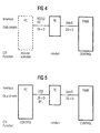
- FIG. 5 shows the cabling between PC, terminal (TE) and private branch exchange, which is required for the information exchange according to FIG. 1.
- the USB bus Since the USB bus is capable of the entire IOM-2 frame structure to transmit, the two IC channels, the two B channels to the private branch exchange and the D channel not only laboriously filtered out of the IOM-2 frame structure become. Because the entire IOM-2 frame structure is transferred to the PC, the PC can be the end device check completely. This also means that the data which the private branch exchange sends to the terminal (downlink) passed on to the PC in a simple manner. Furthermore, the PC by inserting data into the IOM-2 frame structure in simple data indirectly to the private branch exchange send. For direct communication between PC and end device there are two IC channels in each direction (uplink and Downlink).
- the IOM-2 framework structure is not the complete one Bandwidth of the USB bus. Therefore, as in FIG. 6 shown via the USB bus to other peripheral devices the PC can be connected. For example, come here Loudspeakers, additional microphones, chip card readers, speed dial memory, Keyboards, mice and cameras for video telephony in question.
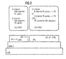
- the nesting of the respective layer 1 is shown in FIG Bit frame structures shown in the terminal.
- the bottom one Layer represents the USB bus.
- the IOM-2 layer corresponds to the Layer 1 of the OSI layer model towards the end device.
- Layer 1 of the OSI model becomes the PC through the USB bus shown.
- Layer 1 implementation of IOM / USB takes place in a layer 1 converter not shown here (e.g. plug-in adapter in phone).
- the LAP layer that of layer 2 of the OSI layer model equivalent.
- Layer 3 of the OSI layer model is referred to as the SIG PROT signaling protocol.
- the signaling protocol SIG PROT can be in two operating states are located. One operating state is the Symphony mode.
- the terminal In symphony mode (see Figure 4 and Figure 6) the terminal is controlled by the PABX private branch exchange.
- the second operating state is the butterfly mode (BFL) (see Figure 5 and Figure 7).
- BFL the butterfly mode
- this leads Terminal data only between PC and private branch exchange without responding to them.
- Data (language) between PC and Terminal devices are exchanged via the two IC channels.
- the terminal receives commands from the PC via the control channel (CTRL) (see also Figure 7). Control commands like Keystrokes, the phone can be connected to the D * channel Send PC.
- FIG. 6 shows the logical flow of information in Symphony mode.
- the terminal communicates with the private branch exchange via the U p0 / E interface.
- the bold connection to the private branch exchange indicates that the private branch exchange controls the terminal.
- the PC can communicate with peripheral devices via the USB bus and with the private branch exchange via the USB bus and the end device.
- the Symphony mode enables calls even when the PC is switched off. In symphony mode, the terminal is controlled by the private branch exchange.
- FIG. 7 shows the communication in butterfly mode.
- the end device (TE) is controlled from the PC via the USB bus. This is shown by the USB lines shown in bold.
- Data is only exchanged between the PC and the private branch exchange (PABX). This data is only passed through by the end device and implemented between the U p0 / E interface and the USB bus.
- the PC controls the end device via the control channel (CTRL). Keystrokes on the phone are transmitted to the PC via the D * channel.
- Data (voice) can be exchanged between the end device and the PC via the IC channels.
- the butterfly architecture enables preprocessing of data from the private branch exchange in the PC and the subsequent Output on the phone.
- Voice input via the phone in the PC before transmission the private branch exchange are preprocessed.
- the PC can carry out voice encryption. He would the voice data coming from the phone is encrypted to the Pass on the private branch exchange. Encrypted voice signals from the private branch exchange to the end device in plain text passed. Since there is only one B channel to the private branch exchange and an IC channel to the terminal is occupied, is the Parallel operation of another B channel application in the PC possible.
- the butterfly architecture is also suitable for the PC to implement an answering machine.
- the PC is drawing stand out due to high computing power and high storage capacity the hard drive. To implement an answering machine function it is therefore in the butterfly architecture sufficient to expand the software on the PC.
- the voice - Input and output is preferably again on the phone.
- other peripheral devices can be used, for example can be connected to the PC.
- the H.320 standard is a standard for narrowband image transmission. Since a screen is already available in the PC, only a camera is required to take the picture. This camera can be connected to the USB bus, for example.
- a B channel of the U p0 / E interface is used for video transmission. The second B channel is available for voice transmission (multiplexed with image data). Voice data is input and output via the phone.
- voice data is first exchanged between the PC and telephone via an IC channel. The PC sends the voice data to the private branch exchange via a B channel. The voice data is passed through the phone. This apparently complicated procedure makes it possible to keep the hardware expenditure, in particular in the telephone, as low as possible and to standardize the telephone software as far as possible.
Landscapes
- Engineering & Computer Science (AREA)
- Signal Processing (AREA)
- Computer Networks & Wireless Communication (AREA)
- Computer Hardware Design (AREA)
- General Engineering & Computer Science (AREA)
- Telephonic Communication Services (AREA)
- Information Transfer Systems (AREA)
Abstract
Description
das Telekommunikationsendgerät über eine Schnittstelle an die Vermittlungseinrichtung angeschlossen ist,
das Telekommunikationsendgerät über einen ersten Betriebsmodus verfügt, in dem die von der Vermittlungseinrichtung empfangenen Empfangsdaten von dem Telekommunikationsendgerät auf das erste Bussystem umgesetzt und über das erste Bussystem an die Computereinrichtung weitergeleitet werden, die Computereinrichtung über Einrichtungen zum Verarbeiten der von dem Telekommunikationsendgerät empfangenen Daten und zum Weiterleiten dieser Daten über das erste Bussystem an das Telekommunikationsendgerät verfügt, wobei die Daten von dem Telekommunikationsendgerät ausgegeben werden,
dadurch ge-kennzeichnet daß das erste Bussystem eine größere Bandbreite aufweist als ein zweites Bussystem, das zur Verbindung einzelner interner Baugruppen des Telekommunikationsendgerätes verwendet wird, und daß in dem ersten Betriebsmodus ferner die von dem Telekommunikationsendgerät erzeuten Sendedaten über das erste Bussystem eine Computereinrichtung weitergeleitet werden, die Computereinrichtung die empfangenen Daten mittels der Verarbeitungseinrichtung verarbeitet und die verarbeiteten Sendedaten über das erste Bussystem an das Telekommunikationsendgerät zurückleitet und das Telekommunikationsendgerät diese Daten zur Weiterleitung an die Vermittlungseinrichtung auf die entsprechende Schnittstelle umsetzt.
- Figur 1
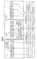
- eine erfindungsgemäße Kopplung zwischen PC und Endgerät über den USB - Bus, wobei der PC indirekt über USB und das PC-Endgerät über eine Up0/E - Schnittstelle mit der Nebenstellenanlage (PABX) verbunden sind, wobei die Bandbreite der USB-Schnittstelle um mindestens die Kanäle 2 IC, D* und CTRL größer ist als die Bandbreite der Upo-Schnittstelle.
- Figur 2
- ein Schichtenmodell für das Endgerät gemäß Figur 1, das sowohl im herkömmlichen Symphony - Mode (BRI) als auch im erfindungsgemäßen Butterfly - Mode (BFL) betrieben werden kann,
- Figur 3
- den logischen Datenfluß bei herkömmlichem Anschluß eines PCs und eines Endgeräts über eine S0 - Schnittstelle oder eine Up0/E - Schnittstelle an eine Nebenstellenanlage (PABX) über 2 B - Kanäle und einen D-Kanal,
- Figur 4
- eine herkömmliche Verkabelung bei Anschluß eines PCs über eine RS - 232 - oder S0 - Schnittstelle über ein Endgerät (TE) an eine Nebenstellenanlage,
- Figur 5
- eine erfindungsgemäß ausgestaltete Butterfly - Architektur, wobei PC und Endgerät (TE) über einen USB-Bus verbunden sind und Endgerät mit der Nebenstellenanlage (PABX) über eine Up0/E - Schnittstelle verbunden sind,
- Figur 6
- eine schematische Darstellung einer Datenübertragung in einer erfindungsgemäßen Butterfly - Architektur im Symphony - Mode, wobei das Endgerät in herkömmlicher Weise von der Nebenstellenanlage gesteuert wird und keine Daten direkt zwischen PC und Endgerät (TE) übertragen werden, und
- Figur 7
- eine schematische Darstellung einer Butterfly - Architektur im erfindungsgemäßen Butterfly - Mode, wobei das Endgerät (TE) vom PC gesteuert wird, wobei ferner das Endgerät die Daten zwischen der Nebenstellenanlage und PC nur weiterreicht und wobei, falls erforderlich, der PC wieder Daten über den USB - Bus an das Endgerät beispielsweise zur Lautsprecherausgabe weiterleitet.
Claims (12)
- Kommunikationssystem mit mindestens einer Computereinrichtung (PC), mindestens einem Telekommunikationsendgerät (TE) und einer Vermittlungseinrichtung (PABX), die an ein öffentliches Fernmeldenetz anschließbar ist, wobeidadurch gekennzeichnet, daßdie Computereinrichtung (PC) und das Telekommunikationsendgerät (TE) über ein erstes Bussystem (USB) verbunden sind,das Telekommunikationsendgerät (TE) über eine Schnittstelle (Up0/E) an die Vermittlungseinrichtung (PABX) angeschlossen ist,das Telekommunikationsendgerät über einen ersten Betriebsmodus verfügt, in dem die von der Vermittlungseinrichtung empfangenen Empfangsdaten von dem Telekommunikationsendgerät auf das erste Bussystem (USB) umgesetzt und über das erste Bussystem an die Computereinrichtung (PC) weitergeleitet werden,die Computereinrichtung (PC) über Einrichtungen zum Verarbeiten der von dem Telekommunikationsendgerät empfangenen Daten und zum Weiterleiten dieser Daten über das erste Bussystem an das Telekommunikationsendgerät verfügt, wobei die Daten von dem Telekommunikationsendgerät ausgegeben werden,
das erste Bussystem (USB) eine größere Bandbreite aufweist als ein zweites Bussystem (IOM-2), das zur Verbindung einzelner interner Baugruppen des Telekommunikationsendgerätes verwendet wird, und daß in dem ersten Betriebsmodus ferner die von dem Telekommunikationsendgerät erzeuten Sendedaten über das erste Bussystem (USB) eine Computereinrichtung (PC) weitergeleitet werden, die Computereinrichtung die empfangenen Daten mittels der Verarbeitungseinrichtung verarbeitet und die verarbeiteten Sendedaten über das erste Bussystem an das Telekommunikationsendgerät zurückleitet und das Telekommunikationsendgerät diese Daten zur Weiterleitung an die Vermittlungseinrichtung auf die entsprechende Schnittstelle umsetzt. - Kommunikationssystem nach Anspruch 1,
dadurch gekennzeichnet, daß die Verarbeitungseinrichtung der Computereinrichtung die von dem Telekommunikationsendgerät erzeugten Sendedaten codiert und die von der Vermittlungseinrichtung empfangenen Empfangsdaten dekodiert. - Kommunikationssystem nach Anspruch 1 oder 2,
dadurch gekennzeichnet, daß das erste Bussystem durch einen USB - Bus und das zweite Bussystem im wesentlichen durch einen IOM - 2 - Multiplexer realisiert wird und alle Daten des IOM - 2 - Multiplexers über das erste Bussystem übertragen werden. - Kommunikationssystem nach Anspruch 3,
dadurch gekennzeichnet, daß die Computereinrichtung (PC) das Telekommunikationsendgerät in dem ersten Betriebsmodus gemäß dem über einen CTRL-Kanal des IOM - 2 - Multiplexers steuert, die Computereinrichtung über einen D* - Kanal des IOM - 2 - Multiplexers Kontrollinformationen vom Telekommunikationsendgerät erhält, wie beispielsweise die während des Drücken bestimmter Tasten des Telekommunikationsendgeräts erzeugten Informationen, und die Computereinrichtung (PC) und das Telekommunikationsendgerät (TE) über IC-Kanäle des IOM - 2 - Multiplexers Daten austauschen. - Kommunikationssystem nach Anspruch 3 oder 4,
dadurch gekennzeichnet, daß das Telekommunikationsendgerät die Daten nur zwischen der Schnittstelle (Upo/E) und B - Kanälen des IOM - Multiplexers umsetzt. - Kommunikationssystem nach einem der Ansprüche 1 bis 5,
dadurch gekennzeichnet, daß die Vermittlungseinrichtung (PABX) eine Nebenstellenanlage ist. - Kommunikationssystem nach Anspruch 6,
dadurch gekennzeichnet, daß die Schnittstelle (Up0/E) eine Up0/E - Schnittstelle ist. - Kommunikationssystem nach einem der Ansprüche 1 bis 7,
dadurch gekennzeichnet, daß das Telekommunikationsendgerät über einen zweiten Betriebsmodus verfügt, in es in herkömmlicher Weise von der Nebenstellenanlage gesteuert wird, wobei in diesem Betriebsmodus ein von der Computereinrichtung (PC) unabhängiger Betrieb möglich ist. - Kommunikationssystem nach einem der Ansprüche 1 bis 8,
dadurch gekennzeichnet, daß das Telekommunikationsendgerät (TE) ein Telefon ist. - Kommunikationssystem nach einem der Ansprüche 3 bis 9,
dadurch gekennzeichnet, daß die Computereinrichtung (PC) über ein Programm verfügt, durch das eine Anrufbeantwortersimulation ermöglicht wird,
wobei die entsprechenden Sendedaten Ansagetexte darstellen, und die Computereinrichtung über Einrichtungen zum Speichern dieser Sendedaten verfügt um die Ansagetexte zeitversetzt und wiederholt über das Telekommunikationsendgerät an die Vermittlungseinrichtung weiterleiten zu können
und wobei die Empfangsdaten, die Nachrichten von Anrufern darstellen, von der Vermittlungseinrichtung (PABX) über das Telekommunikationsendgerät (TE) an die Computereinrichtung gesendet werden, in der Computereinrichtung zwischengespeichert werden und zeitversetzt als Empfangsdaten über das Telekommunikationsendgerät wiedergegeben werden. - Kommunikationssystem nach einem der Ansprüche 1 bis 10,
dadurch gekennzeichnet, daß die Computereinrichtung (PC) über Einrichtungen zur Durchführung von Videokonferenzen verfügt oder mit entsprechenden Peripheriegeräten verbunden ist,
wobei die Computereinrichtung die Empfangsdaten von der Vermittlungseinrichtung über das Telekommunikationsendgerät erhält und nach Bilddaten und Sprachdaten aufteilt, die Bilddaten auf einem Bildschirm der Computereinrichtung anzeigt und die Sprachdaten wieder zu dem Telekommunikationsendgerät zurücksendet, und
die Computereinrichtung Sendedaten aus Sprachdaten und Bilddaten zusammensetzt, wobei die Sprachdaten aus einem Mikrophon des Telekommunikationsendgeräts über das erste Bussystem an die Computereinrichtung übertragen werden und die Sendedaten über das Telekommunikationsendgerät an die Vermittlungseinrichtung gesendet werden. - Kommunikationssystem nach einem der Ansprüche 1 bis 11,
dadurch gekennzeichnet, daß das die Vermittlungseinrichtung (PABX) dem ISDN - Standard entspricht.
Applications Claiming Priority (3)
| Application Number | Priority Date | Filing Date | Title |
|---|---|---|---|
| DE19741772 | 1997-09-22 | ||
| DE19741772 | 1997-09-22 | ||
| PCT/DE1998/002634 WO1999016176A2 (de) | 1997-09-22 | 1998-09-07 | Kommunikationssystem |
Publications (2)
| Publication Number | Publication Date |
|---|---|
| EP1018287A2 EP1018287A2 (de) | 2000-07-12 |
| EP1018287B1 true EP1018287B1 (de) | 2002-01-30 |
Family
ID=7843223
Family Applications (1)
| Application Number | Title | Priority Date | Filing Date |
|---|---|---|---|
| EP98954133A Expired - Lifetime EP1018287B1 (de) | 1997-09-22 | 1998-09-07 | Kommunikationssystem |
Country Status (5)
| Country | Link |
|---|---|
| US (1) | US7088709B1 (de) |
| EP (1) | EP1018287B1 (de) |
| CN (1) | CN1130949C (de) |
| DE (1) | DE59802979D1 (de) |
| WO (1) | WO1999016176A2 (de) |
Families Citing this family (5)
| Publication number | Priority date | Publication date | Assignee | Title |
|---|---|---|---|---|
| DE50208599D1 (de) * | 2002-07-23 | 2006-12-14 | Siemens Ag | Kommunikationssystem und Server für Kommunikationssystem |
| DE10240651A1 (de) * | 2002-09-03 | 2004-03-11 | Siemens Ag | Anordnung zur Sprach-und Datenkommunikation über eine gemeinsame Teilnehmeranschlussleitung |
| EP1496480A1 (de) * | 2003-07-11 | 2005-01-12 | Axalto S.A. | Ein Serviceanbietendes Gerät mit einem zugehörigem tragbarem Speicher und Relais um die Aktivierung einer Anwendung des tragbaren Speichers des ersten Gerätes durch ein zweites Gerät zu erlauben |
| DE102004030838A1 (de) * | 2004-06-25 | 2006-01-19 | Siemens Ag | Kommunikationsarbeitsplatz |
| US8125911B2 (en) * | 2008-11-26 | 2012-02-28 | Cisco Technology, Inc. | First-hop domain reliability measurement and load balancing in a computer network |
Family Cites Families (16)
| Publication number | Priority date | Publication date | Assignee | Title |
|---|---|---|---|---|
| US4748656A (en) * | 1986-03-21 | 1988-05-31 | American Telephone And Telegraph Company | Personal computer--as an interface between a telephone station set and a business communication system |
| FR2641093B1 (de) * | 1988-12-23 | 1994-04-29 | Alcatel Business Systems | |
| DE4008667A1 (de) | 1990-03-17 | 1991-09-19 | Telefonbau & Normalzeit Gmbh | Schaltungsanordnung zum anschluss eines rechners an einem digitalen fernsprechendgeraet |
| US5365577A (en) * | 1990-09-27 | 1994-11-15 | Radish Communications Systems, Inc. | Telecommunication display system |
| DE4221474C2 (de) * | 1992-06-30 | 1994-07-14 | Siemens Ag | Kommunikationssystem für Mehrdienste-Kommunikationsendeinrichtungen in lokalen Netzen |
| US5287352A (en) * | 1992-07-17 | 1994-02-15 | Rolm Company | Method and apparatus to reduce register overhead in a serial digital interface |
| US5689553A (en) * | 1993-04-22 | 1997-11-18 | At&T Corp. | Multimedia telecommunications network and service |
| CA2109534A1 (en) * | 1993-11-19 | 1995-05-20 | Mauricio Peres | Interface device |
| US5483530A (en) * | 1993-12-16 | 1996-01-09 | International Business Machines Corporation | System and method for communicating with digital and analog devices via a single digital interface |
| WO1995022183A1 (en) * | 1994-02-10 | 1995-08-17 | Elonex Technologies, Inc. | Smart phone |
| CA2158408C (en) | 1995-09-15 | 1998-12-08 | Mitel Networks Corporation | Architecture for robust voice cti |
| US5892764A (en) * | 1996-09-16 | 1999-04-06 | Sphere Communications Inc. | ATM LAN telephone system |
| US5974043A (en) * | 1996-09-16 | 1999-10-26 | Solram Electronics Ltd. | System and method for communicating information using the public switched telephone network and a wide area network |
| US6366653B1 (en) * | 1996-09-19 | 2002-04-02 | Acer Incorporated | System for integrating a telephone to a computer |
| US6081841A (en) * | 1998-02-10 | 2000-06-27 | Ricoh Company, Ltd. | Method and apparatus for expanding data rate in an ISDN communication system |
| US5995150A (en) * | 1998-02-20 | 1999-11-30 | Winbond Electronics Corporation America | Dual compressed video bitstream camera for universal serial bus connection |
-
1998
- 1998-09-07 EP EP98954133A patent/EP1018287B1/de not_active Expired - Lifetime
- 1998-09-07 US US09/509,049 patent/US7088709B1/en not_active Expired - Lifetime
- 1998-09-07 CN CN98809411A patent/CN1130949C/zh not_active Expired - Fee Related
- 1998-09-07 DE DE59802979T patent/DE59802979D1/de not_active Expired - Lifetime
- 1998-09-07 WO PCT/DE1998/002634 patent/WO1999016176A2/de not_active Ceased
Also Published As
| Publication number | Publication date |
|---|---|
| CN1130949C (zh) | 2003-12-10 |
| CN1271507A (zh) | 2000-10-25 |
| US7088709B1 (en) | 2006-08-08 |
| WO1999016176A2 (de) | 1999-04-01 |
| WO1999016176A3 (de) | 1999-06-10 |
| DE59802979D1 (de) | 2002-03-14 |
| EP1018287A2 (de) | 2000-07-12 |
Similar Documents
| Publication | Publication Date | Title |
|---|---|---|
| DE3689115T2 (de) | Übertragungseinrichtung. | |
| DE68914961T2 (de) | Fernsprech-Anschlussanordnung für einen Personal-Computer und eine Einrichtung dafür. | |
| DE69425747T2 (de) | Zusatzbusadapter zum gebrauch in einem digitalen telefon | |
| DE69434646T2 (de) | Netz mit digitalen und analogen Ausgängen | |
| DE3780487T2 (de) | Personal-computer als schnittstelle zwischen einem fernsprechgeraet und einem buero-kommunikationssystem. | |
| DE69313666T2 (de) | Fernmeldevermittlungseinrichtung mit programmierbaren Fernmeldediensten, und entsprechende Vorrichtung | |
| DE69126402T2 (de) | Kommunikationssystem mit ISDN-Signalisierung | |
| DE19542122B4 (de) | Lokales Kommunikations-Serversystem | |
| CH662025A5 (de) | Digitale vermittlungsanlage. | |
| EP0687402B1 (de) | Schaltungsanordnung zur integration von edv-systemen bei der benutzung von telefonanlagen | |
| EP0668706A2 (de) | Netzabschlussgerät | |
| DE69213065T2 (de) | ISDN-Analog-Zwischeneinheit | |
| DE19820382A1 (de) | Verfahren und Vorrichtung zur dynamischen Bandbreitenzuordnung zu unabhängigen Daten- und Audiogeräten | |
| DE19937098A1 (de) | Intelligente Zuweisung der Bandbreite für mehrere unabhängige Verbindungen auf einem digitalen Netzwerk | |
| DE3921573C2 (de) | Digitale Kommunikationsvorrichtung | |
| DE4131062C1 (de) | ||
| EP0581087B1 (de) | Verfahren zum Darstellen teilnehmerindividueller Daten beim Übertragen von Signalisierungssignalen und Nachrichtensignalen zwischen Schmalbandnetzen und ATM- Netzen | |
| EP0303870A2 (de) | Modular strukturiertes digitales Kommunikationssystem mit betriebstechnischen und sicherheitstechnischen Komponenten | |
| EP0734186B1 (de) | Verfahren zum Steuern eines Zugangsnetzes sowie Zugangsnetze und Vermittlungsstelle dafür | |
| WO1999016176A2 (de) | Kommunikationssystem | |
| EP1016312A2 (de) | Verfahren und anordnung für eine automatische übersetzung von nachrichten in einem kommunikationssystem | |
| DE3336641A1 (de) | Schaltungsanordnung zur steuerbaren verbindungsherstellung in einer pcm-vermittlungsanlage | |
| DE4116057C1 (de) | ||
| EP0127138A2 (de) | Mit einem Informationsverarbeitungssystem verbundenes Telekommunikationssystem | |
| DE69731613T2 (de) | Vorrichtung und verfahren zur herstellung von verbindungen |
Legal Events
| Date | Code | Title | Description |
|---|---|---|---|
| PUAI | Public reference made under article 153(3) epc to a published international application that has entered the european phase |
Free format text: ORIGINAL CODE: 0009012 |
|
| 17P | Request for examination filed |
Effective date: 20000317 |
|
| AK | Designated contracting states |
Kind code of ref document: A2 Designated state(s): DE FR GB IT |
|
| GRAG | Despatch of communication of intention to grant |
Free format text: ORIGINAL CODE: EPIDOS AGRA |
|
| GRAG | Despatch of communication of intention to grant |
Free format text: ORIGINAL CODE: EPIDOS AGRA |
|
| GRAH | Despatch of communication of intention to grant a patent |
Free format text: ORIGINAL CODE: EPIDOS IGRA |
|
| 17Q | First examination report despatched |
Effective date: 20010711 |
|
| GRAH | Despatch of communication of intention to grant a patent |
Free format text: ORIGINAL CODE: EPIDOS IGRA |
|
| GRAA | (expected) grant |
Free format text: ORIGINAL CODE: 0009210 |
|
| REG | Reference to a national code |
Ref country code: GB Ref legal event code: IF02 |
|
| AK | Designated contracting states |
Kind code of ref document: B1 Designated state(s): DE FR GB IT |
|
| REF | Corresponds to: |
Ref document number: 59802979 Country of ref document: DE Date of ref document: 20020314 |
|
| GBT | Gb: translation of ep patent filed (gb section 77(6)(a)/1977) |
Effective date: 20020407 |
|
| ET | Fr: translation filed | ||
| PLBE | No opposition filed within time limit |
Free format text: ORIGINAL CODE: 0009261 |
|
| STAA | Information on the status of an ep patent application or granted ep patent |
Free format text: STATUS: NO OPPOSITION FILED WITHIN TIME LIMIT |
|
| 26N | No opposition filed | ||
| PGFP | Annual fee paid to national office [announced via postgrant information from national office to epo] |
Ref country code: DE Payment date: 20101124 Year of fee payment: 13 |
|
| PGFP | Annual fee paid to national office [announced via postgrant information from national office to epo] |
Ref country code: GB Payment date: 20110923 Year of fee payment: 14 Ref country code: FR Payment date: 20111005 Year of fee payment: 14 |
|
| PGFP | Annual fee paid to national office [announced via postgrant information from national office to epo] |
Ref country code: IT Payment date: 20110927 Year of fee payment: 14 |
|
| REG | Reference to a national code |
Ref country code: GB Ref legal event code: 732E Free format text: REGISTERED BETWEEN 20121025 AND 20121031 |
|
| REG | Reference to a national code |
Ref country code: FR Ref legal event code: TP Owner name: SIEMENS ENTERPRISE COMMUNICATIONS GMBH & CO. K, DE Effective date: 20130108 |
|
| REG | Reference to a national code |
Ref country code: DE Ref legal event code: R082 Ref document number: 59802979 Country of ref document: DE Representative=s name: FRITZSCHE PATENT, DE |
|
| REG | Reference to a national code |
Ref country code: DE Ref legal event code: R082 Ref document number: 59802979 Country of ref document: DE Representative=s name: FRITZSCHE PATENT, DE Effective date: 20130313 Ref country code: DE Ref legal event code: R081 Ref document number: 59802979 Country of ref document: DE Owner name: SIEMENS ENTERPRISE COMMUNICATIONS GMBH & CO. K, DE Free format text: FORMER OWNER: SIEMENS AKTIENGESELLSCHAFT, 80333 MUENCHEN, DE Effective date: 20130313 |
|
| GBPC | Gb: european patent ceased through non-payment of renewal fee |
Effective date: 20120907 |
|
| REG | Reference to a national code |
Ref country code: FR Ref legal event code: ST Effective date: 20130531 |
|
| REG | Reference to a national code |
Ref country code: DE Ref legal event code: R119 Ref document number: 59802979 Country of ref document: DE Effective date: 20130403 |
|
| PG25 | Lapsed in a contracting state [announced via postgrant information from national office to epo] |
Ref country code: GB Free format text: LAPSE BECAUSE OF NON-PAYMENT OF DUE FEES Effective date: 20120907 Ref country code: DE Free format text: LAPSE BECAUSE OF NON-PAYMENT OF DUE FEES Effective date: 20130403 |
|
| PG25 | Lapsed in a contracting state [announced via postgrant information from national office to epo] |
Ref country code: FR Free format text: LAPSE BECAUSE OF NON-PAYMENT OF DUE FEES Effective date: 20121001 Ref country code: IT Free format text: LAPSE BECAUSE OF NON-PAYMENT OF DUE FEES Effective date: 20120907 |
|
| REG | Reference to a national code |
Ref country code: FR Ref legal event code: CD Owner name: UNIFY GMBH & CO.KG, DE Effective date: 20140429 |