EP1018308A1 - Structure de liaison de blocs et ornement en forme de bande - Google Patents
Structure de liaison de blocs et ornement en forme de bande Download PDFInfo
- Publication number
- EP1018308A1 EP1018308A1 EP99909207A EP99909207A EP1018308A1 EP 1018308 A1 EP1018308 A1 EP 1018308A1 EP 99909207 A EP99909207 A EP 99909207A EP 99909207 A EP99909207 A EP 99909207A EP 1018308 A1 EP1018308 A1 EP 1018308A1
- Authority
- EP
- European Patent Office
- Prior art keywords
- hole
- link
- shaft
- outside
- diameter
- Prior art date
- Legal status (The legal status is an assumption and is not a legal conclusion. Google has not performed a legal analysis and makes no representation as to the accuracy of the status listed.)
- Withdrawn
Links
- 230000000149 penetrating effect Effects 0.000 claims description 3
- 238000000034 method Methods 0.000 description 3
- 238000010276 construction Methods 0.000 description 1
- 230000000694 effects Effects 0.000 description 1
- 238000004519 manufacturing process Methods 0.000 description 1
Images



Classifications
-
- A—HUMAN NECESSITIES
- A44—HABERDASHERY; JEWELLERY
- A44C—PERSONAL ADORNMENTS, e.g. JEWELLERY; COINS
- A44C5/00—Bracelets; Wrist-watch straps; Fastenings for bracelets or wrist-watch straps
- A44C5/02—Link constructions
- A44C5/10—Link constructions not extensible
-
- A—HUMAN NECESSITIES
- A44—HABERDASHERY; JEWELLERY
- A44C—PERSONAL ADORNMENTS, e.g. JEWELLERY; COINS
- A44C5/00—Bracelets; Wrist-watch straps; Fastenings for bracelets or wrist-watch straps
- A44C5/02—Link constructions
- A44C5/10—Link constructions not extensible
- A44C5/107—Link constructions not extensible with links made of more than two elements including connecting elements
Definitions
- the present invention relates to a structure for connecting pins and links of a band and to a personal adornment band, and more particularly to a structure having a feature in a connecting portion of a pin and a link.
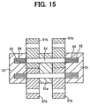
- Fig. 15 shows a part of a conventional watch band.
- a pin 53 has knurls 54 at both end portions.
- the pin 53 is rotatably inserted in a hole of an intermediate link 51a and in holes of connecting links 51b, and the knurl 54 is force fitted in a hole 52 of each side link 51.
- a watch band is formed by connecting links with pins.
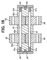
- a pair of pins 61 are inserted in holes of an intermediate link 62b and holes of connecting links 63, and a knurl 61a of each pin 61 is force fitted in a hole of a side link 62a (62c).
- An ornament plate 64 is secured to the outside surface of the side link 62a by a screw 65.
- An object of the present invention is to provide a connecting structure for a link and a pin wherein the connecting strength of the link and pin is increased.
- Another object of the present invention is to provide a personal adornment band wherein the connecting strength between a link and pin is increased with a small number of parts.
- a band link connecting structure is characterized in that the structure comprises, a link having a center connecting portion projecting from a central portion of one of sides of the link in a longitudinal direction of the band, and a pair of outside connecting portions projecting from the other side of the link in the reverse direction, a pair of first holes formed in the center connecting portion, a second hole formed in each of the outside connecting portions, opening to the inside of the outside connecting portion, and having a same diameter as the diameter of the first hole, a third hole formed in the outside connecting portion, opening to the outside of the outside connecting portion, coaxial with the second hole, and having a diameter larger than the second hole, a pair of pins for connecting adjacent links, each of the pins comprising a shaft to be inserted in the first and second holes, a force fit portion having a diameter larger than the diameter of the shaft and to be forcibly fitted in the second and third holes, and a neck portion formed between the shaft and the force fit portion in a taper shape, the adjacent links being connected by inserting the shaft
- the neck portion is tapered toward the force fit portion.
- the neck portion may be tapered toward the shaft.
- the band link connecting structure comprises an inside link, a pair of outside links at both sides of the inside link, a first hole formed in the inside link, penetrating the link, a second hole formed in each of the outside links, opening to the inside of the outside link, and having a same diameter as the diameter of the first hole, a third hole formed in the outside link, coaxial with the second hole, and having a diameter smaller than the second hole, a pin for connecting the inside link and outside links, the pin comprising a shaft to be inserted in the third hole, a force fit portion having a diameter larger than the diameter of the shaft and to be forcibly fitted in the second hole, and a neck portion formed between the shaft and the force fit portion in a taper shape, the inside and outside links being connected by inserting the shaft in the third hole and force fitting the force fit portion in the second hole.
- Figs. 1-3 show a watch band of the first embodiment of the present invention.
- the band comprises links 10 and pins 20.
- the link 10 has a Y shape, comprising a pair of outside connecting portions 11 projecting from one of longitudinal directions of the band, and a center connecting portion 13 projecting from a central portion of the link in the reverse direction.
- the center connecting portion 13 is inserted in a recess formed between the outside connecting portions 11 of the adjacent link 10, and the adjacent links are connected by the pins 20.
- a first hole 14 is formed in each of the outside connecting portions 11 in an inside range, and a second hole 15 having a larger diameter than the first hole 14 at the outside portion of the first hole.
- a pair of holes 12 each having the same diameter as the first hole 14 at the both sides thereof so as to oppose to the first hole 14 when inserted in the recess of the adjacent link.
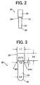
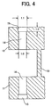
- the pin 20 comprises a shaft 24, a force fit portion 25 having a diameter larger than that of the shaft 24, and a neck portion 21 between the shaft 24 and the force fit potion 25.
- the neck portion 21 is tapered toward the force fit portion 25.
- a chamber 26 is formed on the outer end of the shaft 24 so that the shaft can be easily inserted in the hole 12.
- the inner end of the shaft 24 has a large diameter portion 24c.
- the tapered end of the neck portion 21 is formed into a diameter smaller than that of the shaft 24.
- the shaft 21 is formed so as to be rotatably inserted in the hole 12, and the force fit portion 25 is formed so as to be force fitted in the hole 15.
- the pin 20 of a material harder than the link 10.
- the pin 20 is formed, for example, at dimensions shown in Fig. 3.
- the force fit portion 25 has the length of 2.0mm, the diameter of 1.1mm, the large diameter portion 24c is 1.0mm in diameter, the shaft 24 has the diameter of 0.8mm.
- the neck portion 21 has the diameter of 0.7mm at the smaller end and the inclined angle of 30°. The length of the neck portion 21 and the large diameter portion 24c is 0.7mm.
- the center connecting portion 13 of one of the links is inserted in the recess between the outside connecting portions 11 of the other link, and shaft 24 of each pin 20 is inserted in the holes 12 and 14, and the force fit portion 25 is force fitted in the hole 15.
- the force fit portion 25 abuts on the shoulder of the hole 15 to be stopped.
- the force fit potion 25 is further jammed so that the portion is crushed in the axial direction.
- the diameter of the force fit portion is increased, thereby the contact pressure between the force fit portion and the inner wall of the hole 15 is excessively increased.
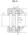
- the link 10 shown in Fig. 4 is different from the link 10 of Fig. 1 in shape.
- the links in Fig. 1 are the same in shape, the adjacent links in Fig. 4 are different in shape.
- the diameter of the first hole 14 is 1.0mm and the diameter of the second hole 15 is 1.1mm which is the same as that of the force fit portion 25 of the pin 20.
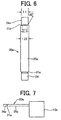
- Figs. 5 through 9 show the third embodiment of the present invention.
- the same parts as the previous embodiments are identified with the same reference numerals as Figs. 1-4, the description thereof is omitted.
- the unit of the band comprises a pair of outside links 10a, a pair of inside links 18, and a pair of pins 20a.
- the first hole and second hole are formed in the outside link 10a, and the hole 12 is formed in the inside link 18.
- shafts 24a are formed on the both ends of the pin 20a.
- a force fit portion 25a is formed in a central portion of the pin 20a.
- a neck portion 21a is formed between the shaft 24a and the force fit portion 25a.
- the shaft 24a has a diameter of 1.1mm, the diameter of the force fit portion 25a is 1.22mm.
- the diameter of the neck portion 21a is 0.7mm.
- the force fit portion 25a is forcibly inserted in the second hole 15, so that the shoulder portion of the second hole 15 is crushed as shown in Fig. 9 by broken lines.
- a wedge portion is formed as shown in Fig. 5, thereby preventing the pin 20a from getting out of the link 10a in the same manner as the first embodiment.
- Fig. 10 shows another example of the outside link 10a.
- the end of the first hole 14 is formed into a cone.
- Fig. 11 shows the fourth embodiment of the present invention.
- the neck portion 21 in the above described embodiment is tapered toward the force fit portion
- the neck portion 21b of the fourth embodiment is tapered toward the shaft 24a.
- the pin may be gotten out of the links when a strong force is applied to the link.
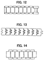
- Figs. 12 through 14 show examples of the shape of the link.
- a sectional wedge shape is formed at the neck portion, thereby preventing the pin from coming off from the link. Consequently, it is not necessary to process knurl on the pin.
- the links can be surely connected by a pin having a simple construction.
Landscapes
- Insertion Pins And Rivets (AREA)
- Adornments (AREA)
- Toys (AREA)
- Clamps And Clips (AREA)
Applications Claiming Priority (3)
| Application Number | Priority Date | Filing Date | Title |
|---|---|---|---|
| JP8509798 | 1998-03-17 | ||
| JP10085097A JPH11262403A (ja) | 1998-03-17 | 1998-03-17 | ピンと駒の結合構造及び結合方法並びに時計バンド |
| PCT/JP1999/001328 WO1999047016A1 (fr) | 1998-03-17 | 1999-03-17 | Structure de liaison de blocs et ornement en forme de bande |
Publications (2)
| Publication Number | Publication Date |
|---|---|
| EP1018308A1 true EP1018308A1 (fr) | 2000-07-12 |
| EP1018308A4 EP1018308A4 (fr) | 2001-06-13 |
Family
ID=13849116
Family Applications (1)
| Application Number | Title | Priority Date | Filing Date |
|---|---|---|---|
| EP99909207A Withdrawn EP1018308A4 (fr) | 1998-03-17 | 1999-03-17 | Structure de liaison de blocs et ornement en forme de bande |
Country Status (6)
| Country | Link |
|---|---|
| EP (1) | EP1018308A4 (fr) |
| JP (1) | JPH11262403A (fr) |
| KR (1) | KR20010012609A (fr) |
| CN (1) | CN1258204A (fr) |
| TW (1) | TW425272B (fr) |
| WO (1) | WO1999047016A1 (fr) |
Cited By (1)
| Publication number | Priority date | Publication date | Assignee | Title |
|---|---|---|---|---|
| EP2462829A1 (fr) * | 2010-12-08 | 2012-06-13 | Rolex S.A. | Bracelet à maillons articulés et utilisation de ce bracelet. |
Families Citing this family (20)
| Publication number | Priority date | Publication date | Assignee | Title |
|---|---|---|---|---|
| JP4819384B2 (ja) * | 2005-03-28 | 2011-11-24 | シチズンホールディングス株式会社 | 帯状装身具 |
| AU2011324026A1 (en) | 2010-11-05 | 2013-06-27 | Cheong Choon Ng | Brunnian link making device and kit |
| US8973955B2 (en) | 2010-11-05 | 2015-03-10 | Choon's Design Llc | Device for forming brunnian links |
| US8899631B2 (en) | 2010-11-05 | 2014-12-02 | Choon's Design Inc. | Brunnian link making device and kit |
| US8622441B1 (en) | 2012-09-25 | 2014-01-07 | Choon's Design Llc | Hand held link making device and kit |
| US9149096B2 (en) | 2012-09-25 | 2015-10-06 | Choon's Design Llc | Hand held link making device and kit |
| CN103202581A (zh) * | 2013-03-28 | 2013-07-17 | 邓湘凌 | 陶瓷表带的连接结构 |
| US8931811B1 (en) | 2013-09-13 | 2015-01-13 | Choon's Design Inc. | Monster tail loom for forming Brunnian links |
| USD748158S1 (en) | 2013-10-01 | 2016-01-26 | Choon's Design Llc | Brunnian link forming loom |
| US20150296937A1 (en) * | 2014-04-17 | 2015-10-22 | Choon's Design Llc | Rotatable pin loom with multi orientation base |
| USD755258S1 (en) | 2014-06-18 | 2016-05-03 | Choon's Design Llc | Hand loom for forming brunnian link articles |
| USD748159S1 (en) | 2014-12-30 | 2016-01-26 | Choon's Design Llc | Loom |
| US20160316865A1 (en) * | 2015-04-30 | 2016-11-03 | Motorola Mobility Llc | Adjustable Wristband and Method for Resizing |
| KR200484983Y1 (ko) * | 2015-08-13 | 2017-11-16 | 에코시계 주식회사 | 세라믹 시계줄 |
| JP7157636B2 (ja) * | 2018-11-19 | 2022-10-20 | シチズン時計株式会社 | バンドの連結構造及びバンドの製造方法 |
| CN112716121B (zh) * | 2020-12-26 | 2022-07-12 | 深圳市鸿亨珠宝首饰有限公司 | 一种链节拼接工艺 |
| CN115299676B (zh) * | 2022-09-19 | 2025-06-27 | 歌尔科技有限公司 | 带粒、表带及腕戴设备 |
| WO2025041491A1 (fr) * | 2023-08-24 | 2025-02-27 | シチズン時計株式会社 | Procédé de fabrication de bande et bande |
| USD1139496S1 (en) | 2024-08-16 | 2026-08-04 | Choon's Design Llc | Auto-loom brunnian link forming loom |
| US12685371B2 (en) | 2024-10-08 | 2026-07-21 | Choon's Design Llc | Loom with rotationally incrementable pins |
Family Cites Families (9)
| Publication number | Priority date | Publication date | Assignee | Title |
|---|---|---|---|---|
| JPS562809U (fr) * | 1979-06-19 | 1981-01-12 | ||
| JPS58168212U (ja) * | 1982-05-06 | 1983-11-09 | 上尾精密株式会社 | 時計バンドの構造 |
| GB2214778A (en) * | 1988-02-17 | 1989-09-13 | Frank Henry Lambert | Watch bracelet |
| DE3910403A1 (de) * | 1989-03-31 | 1990-10-04 | Int Watch Co Iwc | Gliederarmband |
| JPH0333872U (fr) * | 1989-08-10 | 1991-04-03 | ||
| JPH0515816U (ja) * | 1991-08-14 | 1993-03-02 | 森義 林 | 金属バンド用素子 |
| GB2260072A (en) * | 1991-10-01 | 1993-04-07 | Stelux Ind Limited | Bracelet |
| JPH0613519U (ja) * | 1992-07-31 | 1994-02-22 | 上尾精密株式会社 | バンドの構造 |
| FR2717991B1 (fr) * | 1994-03-29 | 1996-05-03 | Burdet Jean L Sa | Procédé d'assemblage d'éléments constitutifs d'articles d'horlogerie-bijouterie. |
-
1998
- 1998-03-17 JP JP10085097A patent/JPH11262403A/ja not_active Withdrawn
-
1999
- 1999-03-16 TW TW088104035A patent/TW425272B/zh not_active IP Right Cessation
- 1999-03-17 EP EP99909207A patent/EP1018308A4/fr not_active Withdrawn
- 1999-03-17 KR KR1019997010568A patent/KR20010012609A/ko not_active Withdrawn
- 1999-03-17 WO PCT/JP1999/001328 patent/WO1999047016A1/fr not_active Ceased
- 1999-03-17 CN CN99800296A patent/CN1258204A/zh active Pending
Cited By (2)
| Publication number | Priority date | Publication date | Assignee | Title |
|---|---|---|---|---|
| EP2462829A1 (fr) * | 2010-12-08 | 2012-06-13 | Rolex S.A. | Bracelet à maillons articulés et utilisation de ce bracelet. |
| US8602638B2 (en) | 2010-12-08 | 2013-12-10 | Rolex S.A. | Bracelet with articulated links and use of this bracelet |
Also Published As
| Publication number | Publication date |
|---|---|
| CN1258204A (zh) | 2000-06-28 |
| WO1999047016A1 (fr) | 1999-09-23 |
| JPH11262403A (ja) | 1999-09-28 |
| KR20010012609A (ko) | 2001-02-15 |
| TW425272B (en) | 2001-03-11 |
| EP1018308A4 (fr) | 2001-06-13 |
Similar Documents
| Publication | Publication Date | Title |
|---|---|---|
| KR20010012609A (ko) | 밴드 링크 연결 구조체 및 장신구 밴드 | |
| US5291730A (en) | Knuckle connector for connecting end knuckles of a chain strand | |
| US7427251B2 (en) | Drive chain for a bicycle | |
| US6059480A (en) | Composite stud | |
| US6485116B1 (en) | Joint assembly to resist galling | |
| JPH01218969A (ja) | シャフトとヨークの結合構造及びその製造方法 | |
| US20060119098A1 (en) | Pipe Joint Structures and Methods of Manufacturing Such Stuctures | |
| JP2002013540A (ja) | 複列旋回軸受 | |
| US6565392B2 (en) | Compliant section for an electrical contact | |
| US5729882A (en) | Methods of assembling a chain and a rivet for use in such assembly | |
| US7351121B2 (en) | Electrical terminal | |
| EP1048240A1 (fr) | Structure de fixation pour blocs, dispositif de raccordement, structures de cheville et bloc de raccordement dans un ornement en forme de bande | |
| US20220255255A1 (en) | Socket, method for producing same, and plug connector | |
| US6619700B2 (en) | Banjo connector for coupling a brake hose to a brake caliper | |
| TWI922975B (zh) | 鏈條 | |
| US20230323908A1 (en) | Coupling Assemblies Having Frangible Portions | |
| US6971570B2 (en) | Striker assembly for a nailer | |
| US7216472B1 (en) | Guiding shaft structure for chain connector | |
| JPH0785822B2 (ja) | トリポッド型継手内側部材の製作方法 | |
| KR20250043016A (ko) | 볼트 제조용 냉간단조 금형의 구조 | |
| CN106461137A (zh) | 具有凸端段和凹端段的尤其用于波纹管的紧固部 | |
| US5899539A (en) | Hub assembly of bicycle | |
| JP2895029B2 (ja) | 鍛造・圧造用工具 | |
| JPH03199707A (ja) | ボールジョイントのボールシート | |
| EP4614026A1 (fr) | Maillon de liaison et chaîne |
Legal Events
| Date | Code | Title | Description |
|---|---|---|---|
| PUAI | Public reference made under article 153(3) epc to a published international application that has entered the european phase |
Free format text: ORIGINAL CODE: 0009012 |
|
| 17P | Request for examination filed |
Effective date: 19991204 |
|
| AK | Designated contracting states |
Kind code of ref document: A1 Designated state(s): CH DE LI |
|
| A4 | Supplementary search report drawn up and despatched |
Effective date: 20010502 |
|
| AK | Designated contracting states |
Kind code of ref document: A4 Designated state(s): CH DE LI |
|
| RAP1 | Party data changed (applicant data changed or rights of an application transferred) |
Owner name: CITIZEN WATCH CO. LTD. |
|
| STAA | Information on the status of an ep patent application or granted ep patent |
Free format text: STATUS: THE APPLICATION IS DEEMED TO BE WITHDRAWN |
|
| 18D | Application deemed to be withdrawn |
Effective date: 20021001 |