EP1018320A2 - Appareil et méthode de fixation d'un stent sur un ballon - Google Patents
Appareil et méthode de fixation d'un stent sur un ballon Download PDFInfo
- Publication number
- EP1018320A2 EP1018320A2 EP99124856A EP99124856A EP1018320A2 EP 1018320 A2 EP1018320 A2 EP 1018320A2 EP 99124856 A EP99124856 A EP 99124856A EP 99124856 A EP99124856 A EP 99124856A EP 1018320 A2 EP1018320 A2 EP 1018320A2
- Authority
- EP
- European Patent Office
- Prior art keywords
- stent
- clamping portion
- crimping
- longitudinal
- sleeve
- Prior art date
- Legal status (The legal status is an assumption and is not a legal conclusion. Google has not performed a legal analysis and makes no representation as to the accuracy of the status listed.)
- Granted
Links
- 238000000034 method Methods 0.000 title claims abstract description 14
- 238000002788 crimping Methods 0.000 claims abstract description 266
- 230000001012 protector Effects 0.000 claims description 39
- 239000000463 material Substances 0.000 claims description 14
- 229920002635 polyurethane Polymers 0.000 claims description 4
- 239000004814 polyurethane Substances 0.000 claims description 4
- 239000002184 metal Substances 0.000 claims description 2
- 230000001788 irregular Effects 0.000 description 7
- 210000004204 blood vessel Anatomy 0.000 description 2
- 208000014674 injury Diseases 0.000 description 2
- 230000008733 trauma Effects 0.000 description 2
- 238000007796 conventional method Methods 0.000 description 1
- 230000003313 weakening effect Effects 0.000 description 1
Images




Classifications
-
- A—HUMAN NECESSITIES
- A61—MEDICAL OR VETERINARY SCIENCE; HYGIENE
- A61M—DEVICES FOR INTRODUCING MEDIA INTO, OR ONTO, THE BODY; DEVICES FOR TRANSDUCING BODY MEDIA OR FOR TAKING MEDIA FROM THE BODY; DEVICES FOR PRODUCING OR ENDING SLEEP OR STUPOR
- A61M25/00—Catheters; Hollow probes
-
- A—HUMAN NECESSITIES
- A61—MEDICAL OR VETERINARY SCIENCE; HYGIENE
- A61F—FILTERS IMPLANTABLE INTO BLOOD VESSELS; PROSTHESES; DEVICES PROVIDING PATENCY TO, OR PREVENTING COLLAPSING OF, TUBULAR STRUCTURES OF THE BODY, e.g. STENTS; ORTHOPAEDIC, NURSING OR CONTRACEPTIVE DEVICES; FOMENTATION; TREATMENT OR PROTECTION OF EYES OR EARS; BANDAGES, DRESSINGS OR ABSORBENT PADS; FIRST-AID KITS
- A61F2/00—Filters implantable into blood vessels; Prostheses, i.e. artificial substitutes or replacements for parts of the body; Appliances for connecting them with the body; Devices providing patency to, or preventing collapsing of, tubular structures of the body, e.g. stents
- A61F2/95—Instruments specially adapted for placement or removal of stents or stent-grafts
- A61F2/958—Inflatable balloons for placing stents or stent-grafts
-
- A—HUMAN NECESSITIES
- A61—MEDICAL OR VETERINARY SCIENCE; HYGIENE
- A61F—FILTERS IMPLANTABLE INTO BLOOD VESSELS; PROSTHESES; DEVICES PROVIDING PATENCY TO, OR PREVENTING COLLAPSING OF, TUBULAR STRUCTURES OF THE BODY, e.g. STENTS; ORTHOPAEDIC, NURSING OR CONTRACEPTIVE DEVICES; FOMENTATION; TREATMENT OR PROTECTION OF EYES OR EARS; BANDAGES, DRESSINGS OR ABSORBENT PADS; FIRST-AID KITS
- A61F2/00—Filters implantable into blood vessels; Prostheses, i.e. artificial substitutes or replacements for parts of the body; Appliances for connecting them with the body; Devices providing patency to, or preventing collapsing of, tubular structures of the body, e.g. stents
- A61F2/95—Instruments specially adapted for placement or removal of stents or stent-grafts
- A61F2/9522—Means for mounting a stent or stent-graft onto or into a placement instrument
-
- A—HUMAN NECESSITIES
- A61—MEDICAL OR VETERINARY SCIENCE; HYGIENE
- A61M—DEVICES FOR INTRODUCING MEDIA INTO, OR ONTO, THE BODY; DEVICES FOR TRANSDUCING BODY MEDIA OR FOR TAKING MEDIA FROM THE BODY; DEVICES FOR PRODUCING OR ENDING SLEEP OR STUPOR
- A61M25/00—Catheters; Hollow probes
- A61M25/10—Balloon catheters
-
- A—HUMAN NECESSITIES
- A61—MEDICAL OR VETERINARY SCIENCE; HYGIENE
- A61F—FILTERS IMPLANTABLE INTO BLOOD VESSELS; PROSTHESES; DEVICES PROVIDING PATENCY TO, OR PREVENTING COLLAPSING OF, TUBULAR STRUCTURES OF THE BODY, e.g. STENTS; ORTHOPAEDIC, NURSING OR CONTRACEPTIVE DEVICES; FOMENTATION; TREATMENT OR PROTECTION OF EYES OR EARS; BANDAGES, DRESSINGS OR ABSORBENT PADS; FIRST-AID KITS
- A61F2/00—Filters implantable into blood vessels; Prostheses, i.e. artificial substitutes or replacements for parts of the body; Appliances for connecting them with the body; Devices providing patency to, or preventing collapsing of, tubular structures of the body, e.g. stents
- A61F2/95—Instruments specially adapted for placement or removal of stents or stent-grafts
- A61F2/958—Inflatable balloons for placing stents or stent-grafts
- A61F2002/9583—Means for holding the stent on the balloon, e.g. using protrusions, adhesives or an outer sleeve
-
- Y—GENERAL TAGGING OF NEW TECHNOLOGICAL DEVELOPMENTS; GENERAL TAGGING OF CROSS-SECTIONAL TECHNOLOGIES SPANNING OVER SEVERAL SECTIONS OF THE IPC; TECHNICAL SUBJECTS COVERED BY FORMER USPC CROSS-REFERENCE ART COLLECTIONS [XRACs] AND DIGESTS
- Y10—TECHNICAL SUBJECTS COVERED BY FORMER USPC
- Y10S—TECHNICAL SUBJECTS COVERED BY FORMER USPC CROSS-REFERENCE ART COLLECTIONS [XRACs] AND DIGESTS
- Y10S623/00—Prosthesis, i.e. artificial body members, parts thereof, or aids and accessories therefor
- Y10S623/909—Method or apparatus for assembling prosthetic
-
- Y—GENERAL TAGGING OF NEW TECHNOLOGICAL DEVELOPMENTS; GENERAL TAGGING OF CROSS-SECTIONAL TECHNOLOGIES SPANNING OVER SEVERAL SECTIONS OF THE IPC; TECHNICAL SUBJECTS COVERED BY FORMER USPC CROSS-REFERENCE ART COLLECTIONS [XRACs] AND DIGESTS
- Y10—TECHNICAL SUBJECTS COVERED BY FORMER USPC
- Y10T—TECHNICAL SUBJECTS COVERED BY FORMER US CLASSIFICATION
- Y10T29/00—Metal working
- Y10T29/49—Method of mechanical manufacture
- Y10T29/49826—Assembling or joining
- Y10T29/49908—Joining by deforming
- Y10T29/49925—Inward deformation of aperture or hollow body wall
- Y10T29/49927—Hollow body is axially joined cup or tube
Definitions
- the present invention relates generally to intravascular stents for implanting into a living body.
- the present invention relates to intravascular stents that are expanded by an inflatable balloon catheter and to a method and apparatus for mounting and securing a stent on a balloon catheter.
- Intravascular stents having a constricted diameter for delivery through a blood vessel and an expanded diameter for applying a radially outwardly extending force for supporting the blood vessel are known in the art.
- Selfexpandable articulated stents are described, for example, in U.S. Patent No. 5,104,404, entitled “Articulated Stent” to Wolff.
- Balloon expandable articulated stents are commercially available under the trade name Palmaz-Schatz Balloon-Expandable stents from Johnson & Johnson International Systems Co.
- the stent In conventional stent mounting and securing procedures, the stent is usually first slid over the distal end of a balloon catheter so that the expandable balloon is disposed within the longitudinal bore of the stent. The stent is then crimped or pinched to mount or secure the stent and maintain its position with respect to the expandable balloon as the balloon catheter is advanced to the target area. This crimping is often done utilizing the fingers or a plier-like device to pinch the stent.
- This conventional mounting and securing means is that it often produces irregular distortion of the stent which could cause trauma to the lumen being treated. Another shortcoming is that it may weaken a portion or portions of the stent which could result in stent failure.
- FIG. 1 shows a conventional balloon catheter 1 and shows a catheter 2, a balloon 3, and a stent 4 mounted on the balloon 3 prior to the stent 4 being secured on the balloon 3.
- FIG. 2 shows the stent of FIG. 1 after it has been secured to the balloon by conventional methods, e.g., by pinching between the fingers or by crimping with a conventional plier-like device. As shown in FIG. 2, the ends of the stent protrude and there is some irregular distortion of the stent between the two ends of the stent.
- FIG. 3 shows a stent securing apparatus 5 constructed in accordance with the invention.
- FIG. 3 shows a first clamping portion 6 having a first clamping portion recess 7 and a second clamping portion 8 having a second clamping portion recess 9.
- the first clamping portion recess 7 and the second clamping portion recess 9 define a longitudinal stent crimping sleeve channel 10 with a selectively variable cross-sectional diameter.
- FIG. 3 shows the first clamping portion 6 and the second clamping portion 8 disposed in a first or non-securing position which provides a first clearance D1 between the first clamping portion 6 and the second clamping portion 8 that is adequate for inserting an uncompressed stent crimping sleeve into the stent crimping sleeve channel 10.
- FIG. 4 shows the first clamping portion 6 and the second clamping portion 8 of FIG. 3 moved to a second or securing position with a second clearance D2 between the first clamping portion 6 and the second clamping portion 8 that is less than that D1.
- the first clamping portion 6 and the second clamping portion 8 are closer to each other than they are when disposed in the first position and, as shown in FIGS. 3 and 4, the crimping sleeve channel 10 has a smaller diameter.
- the crimping sleeve channel 10 has a substantially circular crosssectional diameter.
- the first clamping portion 6 and the second clamping portion 8 may be arranged in a variety of ways well known to those skilled in the art which permits selective movement of the first clamping portion 6 and second clamping portion 8 from the first position to the second position, i.e., toward and away from each other.
- a channel 11 aligns the first clamping portion 6 and second clamping portion 8 and external pressure, e.g., finger pressure may be utilized to move the first clamping portion 6 and 8 from the first position to the second position.
- external pressure e.g., finger pressure
- pneumatic pressure or an electrical motor is utilized to move the clamping portions 6 and 8.
- a pressure gauge and pressure regulator are utilized to control the amount of pressure applied.
- the first and second clamping portions 6 and 8 are mounted on a plier like hinged device.
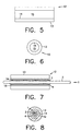
- FIG. 5 is a cross-sectional side view of a stent crimping sleeve 12 having an outer surface 13 and an inner surface 14 defining a longitudinal stent crimping bore 15.
- FIG. 6 is an end view of FIG. 5.
- the stent crimping bore 15 has a selectively variable substantially circular crosssectional diameter that changes in response to external pressure applied to the external surface 13 of the stent crimping sleeve 12.
- the material comprising the stent crimping sleeve 12 is selected from a material which will substantially uniformly vary and maintain the substantially circular cross-sectional diameter of the longitudinal stent crimping bore 15 in response to pressure applied to the outer surface 13 of the stent crimping sleeve 12.
- polyurethane is utilized.
- FIG. 7 shows the stent 4, balloon 3, and catheter 2 of FIG. 1 disposed within the longitudinal stent crimping bore 15 of the stent crimping sleeve 12 shown in FIG. 5 prior to the stent 4 being crimped and secured to the balloon 3.
- FIG. 8 is an end view of FIG. 7.
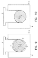
- FIG. 9 shows the stent crimping sleeve 12 of FIGS. 5 and 6 disposed in the stent crimping sleeve channel 10 between the first stent clamping portion 6 and second stent clamping portion 8 of the stent securing apparatus 5.
- the first stent clamping portion 6 and second stent clamping portion 8 are disposed in a first position which provides adequate clearance in the stent crimping sleeve channel 10 for the stent crimping sleeve 12 to be easily inserted or removed from the stent crimping sleeve channel 10.
- Longitudinal bore 15 has a substantially circular cross-sectional diameter D1.
- FIG. 10 differs from FIG. 9 in that the first stent clamping portion 6 and the second stent clamping portion 8 have been moved to a second position.
- the first clamping portion recess 7 and the second clamping portion recess are sized and cooperatively adapted so that when disposed in the second position the first and second clamping portions 6 and 8 define a channel 10 having a substantially circular cross-sectional diameter.
- the stent crimping sleeve 12 is compressed.
- the diameter of the longitudinal stent crimping bore 15 to be reduced substantially uniformly to a substantially circular crosssectional diameter D2 which is less than the uncompressed diameter D1 shown in FIG. 9.
- the inner surface 14 of the stent crimping bore 15 applies a substantially uniform pressure to the stent 4 in an amount sufficient so as to substantially uniformly crimp the stent 4 and secure it on the balloon 3 with minimal irregular distortion of the stent 4 because the longitudinal bore 15 maintains its substantially circular cross-sectional diameter when the stent crimping sleeve 12 is compressed and the diameter of the stent crimping bore 15 is reduced.
- FIG. 11 is a side view of the stent shown in FIG. 1 after it has been secured in accordance with the invention and removed from the stent securing apparatus 5 and shows that the stent 4 has been substantially uniformly crimped and secured on the balloon 3 with minimal irregular distortion.
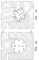
- FIGS. 12 to 16 show an alternative embodiment of the invention that utilizes a plurality of crimping elements disposed between the clamping portions to apply pressure to a stent crimping sleeve.
- FIG. 12 shows a first clamping portion 16 and a second clamping portion 18.
- First clamping portion 16 is provided with a first surface 19, a second surface 20, and a third surface 21 defining a first clamping portion recess 66.
- Second clamping portion 18 is provided with a first surface 22, a second surface 23, a third surface 24, a fourth surface 25 and a fifth surface 26 defining a second clamping portion recess 67.
- the surfaces 19, 20, 21, comprising the first clamping portion recess 66 and the surfaces 22, 23, 24, 25, and 26 comprising the second clamping portion recess 67 define a longitudinal stent crimping element channel 27 with a selectively variable cross-sectional diameter.
- first crimping element 29 is provided with a first crimping element contact surface 33, a second crimping element contact surface 35, a first clamping portion contact surface 34 and a stent crimping sleeve contact surface 36.
- Second crimping element 30 comprises a first crimping element contact surface 37, a second crimping element contact surface 39, a first clamping portion contact surface 38 and a stent crimping sleeve contact surface 40.
- Third crimping element 31 is provided with a first crimping element contact surface 41, a second crimping element contact surface 43, a second clamping portion contact surface 42 and a stent crimping sleeve contact surface 44.
- Fourth crimping element 32 is provided with a first crimping element contact surface 45, a second crimping element contact surface 47, a second clamping portion contact surface 46, and a stent crimping sleeve contact surface 48.
- the stent crimping sleeve contact surfaces 36, 40, 44, and 48 define a stent crimping sleeve channel 10, having a selectively variable crosssectional diameter.
- FIG. 13 shows the first clamping portion 16, the second clamping portion 18, and the crimping elements 29, 30, 31, and 32 disposed in a first or non-securing position, which provides a cross-sectional diameter Di of the stent crimping sleeve channel 101 that is adequate for inserting an uncompressed stent crimping sleeve 12 into the stent crimping sleeve channel 101.
- first clamping portion 16 and second clamping portion 18 may be arranged in a variety of ways well skilled to those skilled in the art which permits selective movement of the first clamping portion 16 and second clamping portion 18 in a first direction away from each other to a first position and in a second direction toward each other to a second position.
- FIGS. 15 and 16 show a stent crimping sleeve 12 (previously discussed) disposed in the longitudinal stent crimping sleeve channel 10' . (The stent and balloon catheter have been omitted for clarity.) As shown in FIG.
- gaps 68 may exist between the outer surface 13 of the stent crimping sleeve 12 and crimping element contact surfaces 36, 40, 44, and 48. As shown in FIG.
- first clamping portion 16, second clamping portion 18, and crimping elements 29, 30, 31, and 32 are disposed in the second or securing position, substantially all of crimping element contact surfaces 36, 40, 44, and 48 are in contact with the external surface 13 of the crimping sleeve 12 because surfaces 36, 40, 44, and 48 are sized and adapted to define a stent crimping sleeve channel 10' having a substantially circular cross-sectional diameter when the first clamping portion 16, the second clamping portion 18, and crimping elements 29, 30, 31, and 32 are disposed in the second position.
- the stent crimping bore 15 has a substantially circular cross-sectional diameter of D1.
- the stent crimping bore 15 has a substantially circular cross-sectional diameter D2 that is smaller than D1.
- the inner surface 14 of the stent crimping sleeve 12 applies substantially uniform pressure to the stent 4 to be crimped mounted on the balloon catheter 1 disposed within the longitudinal stent crimping bore 15 and substantially uniformly crimp and secure the stent 4 to the balloon catheter on which it is mounted with minimal irregular distortion of the stent 4.
- FIGS. 17 to 19 show an alternative embodiment of the invention in which a first catheter protector 60 and a second catheter protector and stent positioner 61 is utilized to protect the catheter shaft and also to limit the movement of the stent along the longitudinal axis of the catheter resulting in more precise placement on the catheter.
- FIG. 17 is a cross-sectional side view and shows a balloon catheter 1, a stent 4, a guide-wire 65, a first catheter protector 60 and a second catheter protector and stent positioner 61.
- FIG. 18A is an end view of the second catheter-protector and positioner 61 shown in FIG. 17
- FIG. 18B is an end view of the first catheter protector 60 shown in FIG. 17. As shown in FIG.
- the second catheter protector and stent positioner 61 is circular in cross-section and comprises an outer ring 62 of compressible material and an inner ring 63 of substantially non-compressible material.
- the inner ring 63 is provided with an inner ring aperture 64 having a substantially circular cross-sectional diameter.
- the first catheter protector 60 is circular in cross-section and comprises an outer ring 62' of compressible material and an inner ring 63' of substantially non-compressible material.
- the inner ring 63' is provided with an inner ring aperture 64' having a substantially circular cross-sectional diameter.
- the substantially compressible material is polyurethane and the substantially non-compressible material is metal.
- FIG. 19 is an enlarged view of the second catheter protector and stent positioner 61 and the first catheter protector 60 of FIG. 17.
- the inner ring aperture 64 of the substantially non-compressible inner ring 63 of the second catheter protector and positioner 61 is sized sufficiently large so as to permit the catheter 2 to enter into the inner ring aperture 64 and is sized sufficiently small so as to prevent the stent 4 from entering into the inner ring aperture 64.
- the inner ring aperture 64 is sized sufficiently small to prevent entrance of the uncrimped stent 4 and is sized sufficiently large to permit entrance of the balloon portion 3 of the catheter 2 into the inner ring aperture 64.
- the inner ring aperture 64 is substantially non-compressible it protects the portions of the catheter 2 and guide-wire 65 disposed within the inner ring aperture 64 of the inner ring 63 during the securing procedure.
- the substantially non-compressible inner ring 63 also acts as a stop to positively position the stent 4 on the catheter 2.
- the balloon portion of the catheter has an external diameter of about 0.9 to about 1.2 mm
- the inner ring aperture 64 of the second catheter protector and stent positioner 61 has a diameter of about 1.4 mm
- the unexpanded and uncrimped stent has an external diameter of about 1.7 to about 1.75 mm
- the crimped stent has a diameter of about 1.0 to about 1.1 mm.
- the first catheter protector 60 has an inner ring aperture 64' that is larger than the inner ring aperture 64 of the second catheter protector and stent positioner 61.
- the inner ring aperture 64' is sized large enough to permit the passage of an uncrimped stent through the inner ring aperture 64' and into the longitudinal stent crimping bore of the stent crimping sleeve. In an especially preferred embodiment a diameter of about 1.9 mm to about 2.0 mm is utilized.
- the uncrimped stent is advanced through the inner ring aperture 64' of the first catheter protector 60 and into the longitudinal stent crimping bore until the stent contacts the second catheter protector and stent positioner 61. Because the second catheter protector and stent positioner 61 has an inner ring aperture 64 that is smaller than the diameter of an uncrimped stent and greater than the diameter of the catheter, the catheter positioner and stent positioner 61 serves both to position the stent and to protect the distal end of the catheter. The catheter is then introduced into the longitudinal bore of the stent and the stent is crimped onto the balloon portion of catheter.
- the catheter with the stent crimped on it is withdrawn by pulling the catheter through the inner ring aperture 64' of the first catheter protector 60.
Landscapes
- Health & Medical Sciences (AREA)
- Engineering & Computer Science (AREA)
- Biomedical Technology (AREA)
- Life Sciences & Earth Sciences (AREA)
- Heart & Thoracic Surgery (AREA)
- Veterinary Medicine (AREA)
- Animal Behavior & Ethology (AREA)
- Public Health (AREA)
- General Health & Medical Sciences (AREA)
- Cardiology (AREA)
- Oral & Maxillofacial Surgery (AREA)
- Vascular Medicine (AREA)
- Transplantation (AREA)
- Biophysics (AREA)
- Pulmonology (AREA)
- Anesthesiology (AREA)
- Hematology (AREA)
- Child & Adolescent Psychology (AREA)
- Media Introduction/Drainage Providing Device (AREA)
Applications Claiming Priority (4)
| Application Number | Priority Date | Filing Date | Title |
|---|---|---|---|
| US360415 | 1994-12-21 | ||
| US21850398A | 1998-12-22 | 1998-12-22 | |
| US218503 | 1998-12-22 | ||
| US09/360,415 US6364870B1 (en) | 1998-12-22 | 1999-07-23 | Apparatus and method for securing a stent on a balloon |
Publications (3)
| Publication Number | Publication Date |
|---|---|
| EP1018320A2 true EP1018320A2 (fr) | 2000-07-12 |
| EP1018320A3 EP1018320A3 (fr) | 2003-06-04 |
| EP1018320B1 EP1018320B1 (fr) | 2005-11-09 |
Family
ID=26912977
Family Applications (1)
| Application Number | Title | Priority Date | Filing Date |
|---|---|---|---|
| EP99124856A Expired - Lifetime EP1018320B1 (fr) | 1998-12-22 | 1999-12-15 | Appareil et méthode de fixation d'un stent sur un ballon |
Country Status (19)
| Country | Link |
|---|---|
| US (1) | US6689123B2 (fr) |
| EP (1) | EP1018320B1 (fr) |
| JP (1) | JP3650783B2 (fr) |
| KR (1) | KR100355189B1 (fr) |
| CN (1) | CN1260213A (fr) |
| AT (1) | ATE308941T1 (fr) |
| AU (2) | AU1582500A (fr) |
| BR (1) | BR9915721A (fr) |
| CA (1) | CA2290889C (fr) |
| DE (2) | DE19960525A1 (fr) |
| EE (1) | EE04139B1 (fr) |
| GB (1) | GB2345858B (fr) |
| IL (1) | IL133350A (fr) |
| NO (1) | NO996380L (fr) |
| NZ (1) | NZ501861A (fr) |
| PL (1) | PL337359A1 (fr) |
| SG (1) | SG76636A1 (fr) |
| SK (1) | SK175799A3 (fr) |
| WO (1) | WO2000036994A2 (fr) |
Cited By (2)
| Publication number | Priority date | Publication date | Assignee | Title |
|---|---|---|---|---|
| WO2002011646A1 (fr) * | 2000-08-03 | 2002-02-14 | Fortimedix B.V. | Dispositif pour sertir un extenseur dans un systeme d'administration de catheter |
| WO2002067813A3 (fr) * | 2001-02-22 | 2002-12-27 | Scimed Life Systems Inc | Dispositif de protection de ballonnet/endoprothese retractable |
Families Citing this family (98)
| Publication number | Priority date | Publication date | Assignee | Title |
|---|---|---|---|---|
| AT413364B (de) * | 2003-03-10 | 2006-02-15 | Schuh Rainer Karl | Spannrahmen für eine plane |
| US7284401B2 (en) * | 2004-01-12 | 2007-10-23 | Boston Scientific Scimed, Inc. | Stent reducing system and device |
| US7945409B2 (en) * | 2004-01-15 | 2011-05-17 | Icon Interventional Systems, Inc. | Method for verifying position on an angioplasty balloon |
| US7207204B2 (en) * | 2004-02-26 | 2007-04-24 | Boston Scientific Scimed, Inc. | Crimper |
| US7389670B1 (en) | 2004-07-26 | 2008-06-24 | Abbott Laboratories | Stent crimping system |
| US7241437B2 (en) * | 2004-12-30 | 2007-07-10 | 3M Innovative Properties Company | Zirconia particles |
| US7563400B2 (en) | 2005-04-12 | 2009-07-21 | Advanced Cardiovascular Systems, Inc. | Method of stent mounting to form a balloon catheter having improved retention of a drug delivery stent |
| US8099851B2 (en) * | 2005-06-27 | 2012-01-24 | Boston Scientific Scimed, Inc. | Crimping and edge protection elements |
| US7658880B2 (en) * | 2005-07-29 | 2010-02-09 | Advanced Cardiovascular Systems, Inc. | Polymeric stent polishing method and apparatus |
| US9585743B2 (en) | 2006-07-31 | 2017-03-07 | Edwards Lifesciences Cardiaq Llc | Surgical implant devices and methods for their manufacture and use |
| EP3360509B1 (fr) | 2006-07-31 | 2022-06-22 | Syntheon TAVR, LLC | Implants endovasculaires scellables |
| US9408607B2 (en) | 2009-07-02 | 2016-08-09 | Edwards Lifesciences Cardiaq Llc | Surgical implant devices and methods for their manufacture and use |
| US9566178B2 (en) | 2010-06-24 | 2017-02-14 | Edwards Lifesciences Cardiaq Llc | Actively controllable stent, stent graft, heart valve and method of controlling same |
| AU2008333855B2 (en) * | 2007-12-04 | 2013-10-24 | Cook Medical Technologies Llc | Tapered loading system for implantable medical devices. |
| WO2009073774A1 (fr) * | 2007-12-04 | 2009-06-11 | Cook Incorporated | Système de stockage et de chargement pour dispositifs médicaux implantables |
| PL2628464T5 (pl) | 2007-12-14 | 2024-10-28 | Edwards Lifesciences Corporation | Zastawka protetyczna |
| ATE556679T1 (de) | 2008-04-09 | 2012-05-15 | Cook Medical Technologies Llc | Ladegerät und verfahren für expandierbare intraluminale medizinische vorrichtungen |
| CA3272239A1 (en) | 2008-06-06 | 2025-10-28 | Edwards Lifesciences Corporation | Low profile transcatheter heart valve |
| US8652202B2 (en) | 2008-08-22 | 2014-02-18 | Edwards Lifesciences Corporation | Prosthetic heart valve and delivery apparatus |
| US8790387B2 (en) | 2008-10-10 | 2014-07-29 | Edwards Lifesciences Corporation | Expandable sheath for introducing an endovascular delivery device into a body |
| US8585019B2 (en) | 2009-08-20 | 2013-11-19 | Cook Medical Technologies Llc | Loading apparatus and system for expandable intraluminal medical devices |
| US8795354B2 (en) | 2010-03-05 | 2014-08-05 | Edwards Lifesciences Corporation | Low-profile heart valve and delivery system |
| US8752261B2 (en) * | 2010-07-07 | 2014-06-17 | Abbott Cardiovascular Systems Inc. | Mounting stents on stent delivery systems |
| CA3020195C (fr) | 2010-10-05 | 2020-10-27 | Edwards Lifesciences Corporation | Valve cardiaque prosthetique |
| US9155619B2 (en) | 2011-02-25 | 2015-10-13 | Edwards Lifesciences Corporation | Prosthetic heart valve delivery apparatus |
| US9339384B2 (en) | 2011-07-27 | 2016-05-17 | Edwards Lifesciences Corporation | Delivery systems for prosthetic heart valve |
| US12364596B2 (en) | 2011-10-21 | 2025-07-22 | Edwards Lifesciences Cardiaq Llc | Actively controllable stent, stent graft, heart valve and method of controlling same |
| US9827093B2 (en) | 2011-10-21 | 2017-11-28 | Edwards Lifesciences Cardiaq Llc | Actively controllable stent, stent graft, heart valve and method of controlling same |
| WO2013120082A1 (fr) | 2012-02-10 | 2013-08-15 | Kassab Ghassan S | Procédés et utilisations de tissus biologiques pour diverses endoprothèses vasculaires et d'autres applications médicales |
| EP3424469A1 (fr) | 2012-02-22 | 2019-01-09 | Syntheon TAVR, LLC | Endoprothèse à commande active, greffe d'endoprothèse et valvule cardiaque |
| US9724219B2 (en) | 2012-10-04 | 2017-08-08 | Abbott Cardiovascular Systems Inc. | Method of uniform crimping and expansion of medical devices |
| EP4215163A1 (fr) | 2013-02-11 | 2023-07-26 | Cook Medical Technologies LLC | Cadre de support extensible et dispositif médical |
| SG10202103500PA (en) | 2013-08-12 | 2021-05-28 | Mitral Valve Tech Sarl | Apparatus and methods for implanting a replacement heart valve |
| EP3068346B1 (fr) | 2013-11-11 | 2021-03-03 | Edwards Lifesciences CardiAQ LLC | Procédé pour fabriquer un stent pour une prothèse de valve |
| US10098734B2 (en) | 2013-12-05 | 2018-10-16 | Edwards Lifesciences Corporation | Prosthetic heart valve and delivery apparatus |
| EP4736932A2 (fr) * | 2014-07-04 | 2026-05-06 | Abiomed Europe GmbH | Gaine pour l'accès étanche à un vaisseau |
| US10016272B2 (en) | 2014-09-12 | 2018-07-10 | Mitral Valve Technologies Sarl | Mitral repair and replacement devices and methods |
| US12194256B2 (en) | 2015-04-10 | 2025-01-14 | Edwards Lifesciences Corporation | Expandable sheath |
| US10327896B2 (en) | 2015-04-10 | 2019-06-25 | Edwards Lifesciences Corporation | Expandable sheath with elastomeric cross sectional portions |
| US10792471B2 (en) | 2015-04-10 | 2020-10-06 | Edwards Lifesciences Corporation | Expandable sheath |
| US10179043B2 (en) | 2016-02-12 | 2019-01-15 | Edwards Lifesciences Corporation | Prosthetic heart valve having multi-level sealing member |
| SG10202108804RA (en) | 2016-03-24 | 2021-09-29 | Edwards Lifesciences Corp | Delivery system for prosthetic heart valve |
| US11096781B2 (en) | 2016-08-01 | 2021-08-24 | Edwards Lifesciences Corporation | Prosthetic heart valve |
| US10973631B2 (en) | 2016-11-17 | 2021-04-13 | Edwards Lifesciences Corporation | Crimping accessory device for a prosthetic valve |
| US10463484B2 (en) | 2016-11-17 | 2019-11-05 | Edwards Lifesciences Corporation | Prosthetic heart valve having leaflet inflow below frame |
| US10603165B2 (en) | 2016-12-06 | 2020-03-31 | Edwards Lifesciences Corporation | Mechanically expanding heart valve and delivery apparatus therefor |
| US11013600B2 (en) | 2017-01-23 | 2021-05-25 | Edwards Lifesciences Corporation | Covered prosthetic heart valve |
| US11185406B2 (en) | 2017-01-23 | 2021-11-30 | Edwards Lifesciences Corporation | Covered prosthetic heart valve |
| US11654023B2 (en) | 2017-01-23 | 2023-05-23 | Edwards Lifesciences Corporation | Covered prosthetic heart valve |
| US10660773B2 (en) | 2017-02-14 | 2020-05-26 | Abbott Cardiovascular Systems Inc. | Crimping methods for thin-walled scaffolds |
| US11135056B2 (en) | 2017-05-15 | 2021-10-05 | Edwards Lifesciences Corporation | Devices and methods of commissure formation for prosthetic heart valve |
| EP3630013B1 (fr) | 2017-05-22 | 2024-04-24 | Edwards Lifesciences Corporation | Dispositif d'ancrage de valvule |
| US12064341B2 (en) | 2017-05-31 | 2024-08-20 | Edwards Lifesciences Corporation | Sealing member for prosthetic heart valve |
| US10869759B2 (en) | 2017-06-05 | 2020-12-22 | Edwards Lifesciences Corporation | Mechanically expandable heart valve |
| US11026785B2 (en) | 2017-06-05 | 2021-06-08 | Edwards Lifesciences Corporation | Mechanically expandable heart valve |
| US10918473B2 (en) | 2017-07-18 | 2021-02-16 | Edwards Lifesciences Corporation | Transcatheter heart valve storage container and crimping mechanism |
| ES2959773T3 (es) | 2017-08-11 | 2024-02-28 | Edwards Lifesciences Corp | Elemento de sellado para válvula cardiaca protésica |
| US11083575B2 (en) | 2017-08-14 | 2021-08-10 | Edwards Lifesciences Corporation | Heart valve frame design with non-uniform struts |
| US10932903B2 (en) | 2017-08-15 | 2021-03-02 | Edwards Lifesciences Corporation | Skirt assembly for implantable prosthetic valve |
| US10898319B2 (en) | 2017-08-17 | 2021-01-26 | Edwards Lifesciences Corporation | Sealing member for prosthetic heart valve |
| US10973628B2 (en) | 2017-08-18 | 2021-04-13 | Edwards Lifesciences Corporation | Pericardial sealing member for prosthetic heart valve |
| US10722353B2 (en) | 2017-08-21 | 2020-07-28 | Edwards Lifesciences Corporation | Sealing member for prosthetic heart valve |
| US10973629B2 (en) | 2017-09-06 | 2021-04-13 | Edwards Lifesciences Corporation | Sealing member for prosthetic heart valve |
| US11147667B2 (en) | 2017-09-08 | 2021-10-19 | Edwards Lifesciences Corporation | Sealing member for prosthetic heart valve |
| US10555825B2 (en) | 2017-11-09 | 2020-02-11 | Abbott Cardiovascular Systems Inc. | Rotation of a medical device during crimping |
| EP3498233A1 (fr) * | 2017-12-14 | 2019-06-19 | Biotronik AG | Procédé et dispositif de détermination d'une force suffisante d'enlèvement d'un stent |
| US11318011B2 (en) | 2018-04-27 | 2022-05-03 | Edwards Lifesciences Corporation | Mechanically expandable heart valve with leaflet clamps |
| US10967556B2 (en) | 2018-06-11 | 2021-04-06 | Abbott Cardiovascular Systems Inc. | Uniform expansion of thin-walled scaffolds |
| JP7407812B2 (ja) | 2018-07-06 | 2024-01-04 | クック・メディカル・テクノロジーズ・リミテッド・ライアビリティ・カンパニー | ストレージ装置、ローディング装置、供給システム、キット及び関連する方法 |
| US12161551B2 (en) | 2018-08-30 | 2024-12-10 | Edwards Lifesciences Corporation | Systems and methods for sizing and implanting prosthetic heart valves |
| CN118975871A (zh) | 2018-10-19 | 2024-11-19 | 爱德华兹生命科学公司 | 具有非圆柱形框架的假体心脏瓣膜 |
| US12310847B2 (en) | 2018-10-19 | 2025-05-27 | Edwards Lifesciences Corporation | Prosthetic heart valve having non-cylindrical frame |
| CR20210226A (es) | 2018-10-30 | 2021-10-01 | Edwards Lifesciences Corp | Control de diámetro de válvula y fuerza de una válvula cardiaca protésica |
| JP7525503B2 (ja) | 2018-10-30 | 2024-07-30 | エドワーズ ライフサイエンシーズ コーポレイション | 人工弁送達アセンブリ |
| WO2020117887A1 (fr) | 2018-12-06 | 2020-06-11 | Edwards Lifesciences Corporation | Valvule cardiaque prothétique à expansion mécanique et appareil de pose |
| CN117838388A (zh) | 2019-01-17 | 2024-04-09 | 爱德华兹生命科学公司 | 用于假体心脏瓣膜的框架 |
| CN113613594B (zh) | 2019-01-28 | 2024-11-26 | 爱德华兹生命科学公司 | 假体瓣膜 |
| CN113613596B (zh) | 2019-02-13 | 2024-11-12 | 爱德华兹生命科学公司 | 具有非均匀支柱的心脏瓣膜框架设计 |
| CN109875663B (zh) * | 2019-03-04 | 2024-12-13 | 武欣 | 一种子宫癌变阴道管封闭阻断装置 |
| EP3934582A1 (fr) | 2019-03-04 | 2022-01-12 | Edwards Lifesciences Corporation | Fixation de commissure pour valve cardiaque prothétique |
| WO2020198273A2 (fr) | 2019-03-26 | 2020-10-01 | Edwards Lifesciences Corporation | Prothèse valvulaire cardiaque |
| EP3946159A1 (fr) | 2019-03-27 | 2022-02-09 | Edwards Lifesciences Corporation | Élément d'étanchéité pour valvule prothétique |
| EP3952789B1 (fr) | 2019-04-11 | 2024-05-15 | Edwards Lifesciences Corporation | Procédé d'assemblage d'une valvule cardiaque prothétique |
| EP3999000A1 (fr) | 2019-07-19 | 2022-05-25 | Edwards Lifesciences Corporation | Dispositifs de sertissage pour valves cardiaques prothétiques |
| CN114025712A (zh) | 2019-08-12 | 2022-02-08 | 爱德华兹生命科学公司 | 人工心脏瓣膜 |
| CN216394380U (zh) | 2019-12-06 | 2022-04-29 | 爱德华兹生命科学公司 | 递送组件 |
| WO2021141878A1 (fr) | 2020-01-10 | 2021-07-15 | Edwards Lifesciences Corporation | Procédés et ensembles pour un feuillet de valvule cardiaque prothétique |
| WO2021178317A1 (fr) | 2020-03-03 | 2021-09-10 | Edwards Lifesciences Corporation | Ensembles de commissures de feuillets de valvules prothétiques cardiaques et méthodes associées |
| KR20220150321A (ko) | 2020-03-06 | 2022-11-10 | 에드워즈 라이프사이언시스 코포레이션 | 볼 조인트가 있는 노즈콘을 갖는 전달 장치 |
| CN115666455A (zh) * | 2020-04-02 | 2023-01-31 | 爱德华兹生命科学公司 | 液压植入物卷曲系统和方法 |
| ES3015213T3 (en) | 2020-06-18 | 2025-04-30 | Edwards Lifesciences Corp | Crimping methods |
| CN216823784U (zh) | 2020-07-10 | 2022-06-28 | 爱德华兹生命科学公司 | 假体瓣膜和递送组件 |
| CN216570344U (zh) | 2020-07-10 | 2022-05-24 | 爱德华兹生命科学公司 | 假体瓣膜 |
| EP4225212A1 (fr) | 2020-10-06 | 2023-08-16 | Edwards Lifesciences Corporation | Élément de verrouillage de commissure |
| EP4243734A1 (fr) | 2020-11-12 | 2023-09-20 | Edwards Lifesciences Corporation | Procédés et ensembles de cuspides de valve prothétique |
| EP4281014A1 (fr) | 2021-01-20 | 2023-11-29 | Edwards Lifesciences Corporation | Jupe de liaison permettant de fixer un feuillet au cadre d'une valvule cardiaque prothétique |
| AU2022242802A1 (en) | 2021-03-23 | 2023-09-14 | Edwards Lifesciences Corporation | Prosthetic heart valve having elongated sealing member |
| USD1054562S1 (en) | 2022-08-31 | 2024-12-17 | Edwards Lifesciences Corporation | Leaflet for a prosthetic heart valve |
Citations (1)
| Publication number | Priority date | Publication date | Assignee | Title |
|---|---|---|---|---|
| US5104404A (en) | 1989-10-02 | 1992-04-14 | Medtronic, Inc. | Articulated stent |
Family Cites Families (20)
| Publication number | Priority date | Publication date | Assignee | Title |
|---|---|---|---|---|
| US3575036A (en) * | 1967-09-13 | 1971-04-13 | Amp Inc | Crimping tool and die assembly |
| US5183085A (en) | 1991-09-27 | 1993-02-02 | Hans Timmermans | Method and apparatus for compressing a stent prior to insertion |
| US5437083A (en) | 1993-05-24 | 1995-08-01 | Advanced Cardiovascular Systems, Inc. | Stent-loading mechanism |
| US5353623A (en) | 1994-04-15 | 1994-10-11 | Bobenhausen Larry F | Portable elastomeric hose crimping tool |
| DE19532288A1 (de) | 1995-09-01 | 1997-03-06 | Ulrich Dipl Phys Dr M Solzbach | Hilfsvorrichtung zum Aufbringen einer Gefäßstütze (Stent) auf einen Ballon eines Dilatationskatheters |
| US5746764A (en) | 1995-12-04 | 1998-05-05 | Atrion Medical Products, Inc. | Stent compression instrument |
| US5626604A (en) * | 1995-12-05 | 1997-05-06 | Cordis Corporation | Hand held stent crimping device |
| US5720197A (en) * | 1996-03-08 | 1998-02-24 | Aeroquip Corporation | Crimper assembly |
| US5672169A (en) * | 1996-04-10 | 1997-09-30 | Medtronic, Inc. | Stent mounting device |
| US5630830A (en) | 1996-04-10 | 1997-05-20 | Medtronic, Inc. | Device and method for mounting stents on delivery systems |
| US5725519A (en) * | 1996-09-30 | 1998-03-10 | Medtronic Instent Israel Ltd. | Stent loading device for a balloon catheter |
| US5893867A (en) * | 1996-11-06 | 1999-04-13 | Percusurge, Inc. | Stent positioning apparatus and method |
| US5893868A (en) * | 1997-03-05 | 1999-04-13 | Scimed Life Systems, Inc. | Catheter with removable balloon protector and stent delivery system with removable stent protector |
| US5810838A (en) * | 1997-03-13 | 1998-09-22 | Solar; Ronald J. | Hydraulic method and apparatus for uniform radial compression and catheter mounting of radially expandable intraluminal stents and stented grafts |
| US5992000A (en) * | 1997-10-16 | 1999-11-30 | Scimed Life Systems, Inc. | Stent crimper |
| US6024737A (en) | 1998-02-25 | 2000-02-15 | Advanced Cardiovascular Systems, Inc. | Stent crimping device |
| US6009614A (en) | 1998-04-21 | 2000-01-04 | Advanced Cardiovascular Systems, Inc. | Stent crimping tool and method of use |
| US5931851A (en) * | 1998-04-21 | 1999-08-03 | Advanced Cardiovascular Systems, Inc. | Method and apparatus for rubber-tube crimping tool with premount stent |
| US5951540A (en) * | 1998-10-22 | 1999-09-14 | Medtronic, Inc. | Device and method for mounting stents |
| US6364870B1 (en) * | 1998-12-22 | 2002-04-02 | Medinol Ltd. | Apparatus and method for securing a stent on a balloon |
-
1999
- 1999-11-12 SG SG1999005632A patent/SG76636A1/en unknown
- 1999-11-25 CA CA002290889A patent/CA2290889C/fr not_active Expired - Lifetime
- 1999-12-06 WO PCT/IL1999/000663 patent/WO2000036994A2/fr not_active Ceased
- 1999-12-06 AU AU15825/00A patent/AU1582500A/en not_active Abandoned
- 1999-12-06 IL IL133350A patent/IL133350A/en not_active IP Right Cessation
- 1999-12-14 SK SK1757-99A patent/SK175799A3/sk unknown
- 1999-12-15 AT AT99124856T patent/ATE308941T1/de not_active IP Right Cessation
- 1999-12-15 DE DE19960525A patent/DE19960525A1/de not_active Withdrawn
- 1999-12-15 DE DE69928207T patent/DE69928207T2/de not_active Expired - Lifetime
- 1999-12-15 EP EP99124856A patent/EP1018320B1/fr not_active Expired - Lifetime
- 1999-12-16 GB GB9929617A patent/GB2345858B/en not_active Revoked
- 1999-12-16 AU AU65303/99A patent/AU768391B2/en not_active Expired
- 1999-12-16 NZ NZ501861A patent/NZ501861A/en unknown
- 1999-12-17 KR KR1019990058488A patent/KR100355189B1/ko not_active Expired - Fee Related
- 1999-12-21 CN CN99126913A patent/CN1260213A/zh active Pending
- 1999-12-21 NO NO996380A patent/NO996380L/no not_active Application Discontinuation
- 1999-12-21 EE EEP199900498A patent/EE04139B1/xx not_active IP Right Cessation
- 1999-12-21 JP JP36217399A patent/JP3650783B2/ja not_active Expired - Fee Related
- 1999-12-21 BR BR9915721-7A patent/BR9915721A/pt not_active IP Right Cessation
- 1999-12-21 PL PL99337359A patent/PL337359A1/xx not_active Application Discontinuation
-
2001
- 2001-11-07 US US10/045,262 patent/US6689123B2/en not_active Expired - Lifetime
Patent Citations (1)
| Publication number | Priority date | Publication date | Assignee | Title |
|---|---|---|---|---|
| US5104404A (en) | 1989-10-02 | 1992-04-14 | Medtronic, Inc. | Articulated stent |
Cited By (4)
| Publication number | Priority date | Publication date | Assignee | Title |
|---|---|---|---|---|
| WO2002011646A1 (fr) * | 2000-08-03 | 2002-02-14 | Fortimedix B.V. | Dispositif pour sertir un extenseur dans un systeme d'administration de catheter |
| WO2002067813A3 (fr) * | 2001-02-22 | 2002-12-27 | Scimed Life Systems Inc | Dispositif de protection de ballonnet/endoprothese retractable |
| US6783542B2 (en) | 2001-02-22 | 2004-08-31 | Scimed Life Systems, Inc | Crimpable balloon/stent protector |
| US7998184B2 (en) | 2001-02-22 | 2011-08-16 | Boston Scientific Scimed, Inc. | Crimpable balloon stent protector |
Also Published As
| Publication number | Publication date |
|---|---|
| PL337359A1 (en) | 2000-07-03 |
| DE19960525A1 (de) | 2000-06-29 |
| GB2345858B (en) | 2003-07-30 |
| CA2290889A1 (fr) | 2000-06-22 |
| DE69928207D1 (de) | 2005-12-15 |
| CA2290889C (fr) | 2004-08-24 |
| DE69928207T2 (de) | 2006-07-13 |
| WO2000036994A2 (fr) | 2000-06-29 |
| AU6530399A (en) | 2000-06-29 |
| EE04139B1 (et) | 2003-10-15 |
| NO996380D0 (no) | 1999-12-21 |
| SG76636A1 (en) | 2000-11-21 |
| IL133350A0 (en) | 2001-04-30 |
| EP1018320A3 (fr) | 2003-06-04 |
| GB9929617D0 (en) | 2000-02-09 |
| EE9900498A (et) | 2000-08-15 |
| BR9915721A (pt) | 2001-08-07 |
| IL133350A (en) | 2006-08-20 |
| SK175799A3 (en) | 2000-08-14 |
| KR20000057066A (ko) | 2000-09-15 |
| KR100355189B1 (ko) | 2002-10-11 |
| AU768391B2 (en) | 2003-12-11 |
| JP2000185104A (ja) | 2000-07-04 |
| NO996380L (no) | 2000-06-23 |
| ATE308941T1 (de) | 2005-11-15 |
| NZ501861A (en) | 2001-11-30 |
| US6689123B2 (en) | 2004-02-10 |
| JP3650783B2 (ja) | 2005-05-25 |
| EP1018320B1 (fr) | 2005-11-09 |
| AU1582500A (en) | 2000-07-12 |
| US20020107507A1 (en) | 2002-08-08 |
| CN1260213A (zh) | 2000-07-19 |
| GB2345858A (en) | 2000-07-26 |
Similar Documents
| Publication | Publication Date | Title |
|---|---|---|
| US6689123B2 (en) | Apparatus and method for securing a stent on a balloon | |
| US6364870B1 (en) | Apparatus and method for securing a stent on a balloon | |
| US6141855A (en) | Stent crimping tool and method of use | |
| US5672169A (en) | Stent mounting device | |
| US5725519A (en) | Stent loading device for a balloon catheter | |
| US6309383B1 (en) | Stent crimper apparatus with radiation shied | |
| US5860966A (en) | Method of securing a stent on a balloon catheter | |
| US5693066A (en) | Stent mounting and transfer device and method | |
| JP3814580B2 (ja) | ソックス部の潤滑剤充填ポート | |
| US5620457A (en) | Catheter balloon | |
| US6878158B2 (en) | Process for coupling an angioplasty stent to a corresponding insertion element, and kit thus formed | |
| EP0938880A2 (fr) | Appareil manuel pour comprimer un stent | |
| US20020198559A1 (en) | Radiopaque balloon | |
| EP0834293A1 (fr) | Cathéter et ballonnet pour placer un stent | |
| EP0903122A2 (fr) | Outil de sertissage de type collet | |
| EP0812579A1 (fr) | Porthèse endovasculaire | |
| JPH11512313A (ja) | バルーン・カテーテル上に血管内ステントを設置するためのデバイス及び方法 | |
| US20030060876A1 (en) | Graft delivery system | |
| MXPA99012025A (en) | Apparatus and method to secure a stent on a gl | |
| CZ9904492A3 (cs) | Přístroj a způsob pro zajištění roztažitelného stentu, majícího podélný kanál, na balónkovém katetru | |
| EP0990427A3 (fr) | Systemes et procedes pour monter un stent sur un catheter |
Legal Events
| Date | Code | Title | Description |
|---|---|---|---|
| PUAI | Public reference made under article 153(3) epc to a published international application that has entered the european phase |
Free format text: ORIGINAL CODE: 0009012 |
|
| AK | Designated contracting states |
Kind code of ref document: A2 Designated state(s): AT BE CH CY DE DK ES FI FR GB GR IE IT LI LU MC NL PT SE |
|
| AX | Request for extension of the european patent |
Free format text: AL;LT;LV;MK;RO;SI |
|
| PUAL | Search report despatched |
Free format text: ORIGINAL CODE: 0009013 |
|
| AK | Designated contracting states |
Designated state(s): AT BE CH CY DE DK ES FI FR GB GR IE IT LI LU MC NL PT SE |
|
| AX | Request for extension of the european patent |
Extension state: AL LT LV MK RO SI |
|
| 17P | Request for examination filed |
Effective date: 20031007 |
|
| AKX | Designation fees paid |
Designated state(s): AT BE CH CY DE DK ES FI FR GB GR IE IT LI LU MC NL PT SE |
|
| AXX | Extension fees paid |
Extension state: SI Payment date: 20031007 Extension state: RO Payment date: 20031007 Extension state: MK Payment date: 20031007 Extension state: LV Payment date: 20031007 Extension state: LT Payment date: 20031007 Extension state: AL Payment date: 20031007 |
|
| 17Q | First examination report despatched |
Effective date: 20040903 |
|
| GRAP | Despatch of communication of intention to grant a patent |
Free format text: ORIGINAL CODE: EPIDOSNIGR1 |
|
| GRAS | Grant fee paid |
Free format text: ORIGINAL CODE: EPIDOSNIGR3 |
|
| GRAA | (expected) grant |
Free format text: ORIGINAL CODE: 0009210 |
|
| AK | Designated contracting states |
Kind code of ref document: B1 Designated state(s): AT BE CH CY DE DK ES FI FR GB GR IE IT LI LU MC NL PT SE |
|
| AX | Request for extension of the european patent |
Extension state: AL LT LV MK RO SI |
|
| PG25 | Lapsed in a contracting state [announced via postgrant information from national office to epo] |
Ref country code: LI Free format text: LAPSE BECAUSE OF FAILURE TO SUBMIT A TRANSLATION OF THE DESCRIPTION OR TO PAY THE FEE WITHIN THE PRESCRIBED TIME-LIMIT Effective date: 20051109 Ref country code: FI Free format text: LAPSE BECAUSE OF FAILURE TO SUBMIT A TRANSLATION OF THE DESCRIPTION OR TO PAY THE FEE WITHIN THE PRESCRIBED TIME-LIMIT Effective date: 20051109 Ref country code: CH Free format text: LAPSE BECAUSE OF FAILURE TO SUBMIT A TRANSLATION OF THE DESCRIPTION OR TO PAY THE FEE WITHIN THE PRESCRIBED TIME-LIMIT Effective date: 20051109 Ref country code: BE Free format text: LAPSE BECAUSE OF FAILURE TO SUBMIT A TRANSLATION OF THE DESCRIPTION OR TO PAY THE FEE WITHIN THE PRESCRIBED TIME-LIMIT Effective date: 20051109 Ref country code: AT Free format text: LAPSE BECAUSE OF FAILURE TO SUBMIT A TRANSLATION OF THE DESCRIPTION OR TO PAY THE FEE WITHIN THE PRESCRIBED TIME-LIMIT Effective date: 20051109 |
|
| REG | Reference to a national code |
Ref country code: GB Ref legal event code: FG4D |
|
| REG | Reference to a national code |
Ref country code: CH Ref legal event code: EP |
|
| REG | Reference to a national code |
Ref country code: IE Ref legal event code: FG4D |
|
| PG25 | Lapsed in a contracting state [announced via postgrant information from national office to epo] |
Ref country code: CY Free format text: LAPSE BECAUSE OF FAILURE TO SUBMIT A TRANSLATION OF THE DESCRIPTION OR TO PAY THE FEE WITHIN THE PRESCRIBED TIME-LIMIT Effective date: 20051215 |
|
| REF | Corresponds to: |
Ref document number: 69928207 Country of ref document: DE Date of ref document: 20051215 Kind code of ref document: P |
|
| PG25 | Lapsed in a contracting state [announced via postgrant information from national office to epo] |
Ref country code: MC Free format text: LAPSE BECAUSE OF NON-PAYMENT OF DUE FEES Effective date: 20051231 |
|
| PG25 | Lapsed in a contracting state [announced via postgrant information from national office to epo] |
Ref country code: LU Free format text: LAPSE BECAUSE OF NON-PAYMENT OF DUE FEES Effective date: 20060109 |
|
| PG25 | Lapsed in a contracting state [announced via postgrant information from national office to epo] |
Ref country code: SE Free format text: LAPSE BECAUSE OF FAILURE TO SUBMIT A TRANSLATION OF THE DESCRIPTION OR TO PAY THE FEE WITHIN THE PRESCRIBED TIME-LIMIT Effective date: 20060209 Ref country code: GR Free format text: LAPSE BECAUSE OF FAILURE TO SUBMIT A TRANSLATION OF THE DESCRIPTION OR TO PAY THE FEE WITHIN THE PRESCRIBED TIME-LIMIT Effective date: 20060209 Ref country code: DK Free format text: LAPSE BECAUSE OF FAILURE TO SUBMIT A TRANSLATION OF THE DESCRIPTION OR TO PAY THE FEE WITHIN THE PRESCRIBED TIME-LIMIT Effective date: 20060209 |
|
| PG25 | Lapsed in a contracting state [announced via postgrant information from national office to epo] |
Ref country code: ES Free format text: LAPSE BECAUSE OF FAILURE TO SUBMIT A TRANSLATION OF THE DESCRIPTION OR TO PAY THE FEE WITHIN THE PRESCRIBED TIME-LIMIT Effective date: 20060220 |
|
| PG25 | Lapsed in a contracting state [announced via postgrant information from national office to epo] |
Ref country code: PT Free format text: LAPSE BECAUSE OF FAILURE TO SUBMIT A TRANSLATION OF THE DESCRIPTION OR TO PAY THE FEE WITHIN THE PRESCRIBED TIME-LIMIT Effective date: 20060410 |
|
| LTIE | Lt: invalidation of european patent or patent extension |
Effective date: 20051109 |
|
| REG | Reference to a national code |
Ref country code: CH Ref legal event code: PL |
|
| ET | Fr: translation filed | ||
| PLBE | No opposition filed within time limit |
Free format text: ORIGINAL CODE: 0009261 |
|
| STAA | Information on the status of an ep patent application or granted ep patent |
Free format text: STATUS: NO OPPOSITION FILED WITHIN TIME LIMIT |
|
| 26N | No opposition filed |
Effective date: 20060810 |
|
| REG | Reference to a national code |
Ref country code: FR Ref legal event code: PLFP Year of fee payment: 17 |
|
| REG | Reference to a national code |
Ref country code: FR Ref legal event code: PLFP Year of fee payment: 18 |
|
| PG25 | Lapsed in a contracting state [announced via postgrant information from national office to epo] |
Ref country code: IT Free format text: LAPSE BECAUSE OF NON-PAYMENT OF DUE FEES Effective date: 20151215 |
|
| PG25 | Lapsed in a contracting state [announced via postgrant information from national office to epo] |
Ref country code: IT Free format text: LAPSE BECAUSE OF NON-PAYMENT OF DUE FEES Effective date: 20151215 |
|
| PGRI | Patent reinstated in contracting state [announced from national office to epo] |
Ref country code: IT Effective date: 20170710 |
|
| REG | Reference to a national code |
Ref country code: FR Ref legal event code: PLFP Year of fee payment: 19 |
|
| PGFP | Annual fee paid to national office [announced via postgrant information from national office to epo] |
Ref country code: IE Payment date: 20181227 Year of fee payment: 20 |
|
| PGFP | Annual fee paid to national office [announced via postgrant information from national office to epo] |
Ref country code: GB Payment date: 20181227 Year of fee payment: 20 |
|
| PGFP | Annual fee paid to national office [announced via postgrant information from national office to epo] |
Ref country code: NL Payment date: 20181226 Year of fee payment: 20 Ref country code: FR Payment date: 20181226 Year of fee payment: 20 Ref country code: IT Payment date: 20181220 Year of fee payment: 20 Ref country code: DE Payment date: 20181231 Year of fee payment: 20 |
|
| REG | Reference to a national code |
Ref country code: DE Ref legal event code: R071 Ref document number: 69928207 Country of ref document: DE |
|
| REG | Reference to a national code |
Ref country code: NL Ref legal event code: MK Effective date: 20191214 |
|
| REG | Reference to a national code |
Ref country code: GB Ref legal event code: PE20 Expiry date: 20191214 |
|
| PG25 | Lapsed in a contracting state [announced via postgrant information from national office to epo] |
Ref country code: GB Free format text: LAPSE BECAUSE OF EXPIRATION OF PROTECTION Effective date: 20191214 |
|
| REG | Reference to a national code |
Ref country code: IE Ref legal event code: MK9A |
|
| PG25 | Lapsed in a contracting state [announced via postgrant information from national office to epo] |
Ref country code: IE Free format text: LAPSE BECAUSE OF EXPIRATION OF PROTECTION Effective date: 20191215 |