EP1018434A2 - Anordnung zur Ablage von Aufzeichungsträgern - Google Patents
Anordnung zur Ablage von Aufzeichungsträgern Download PDFInfo
- Publication number
- EP1018434A2 EP1018434A2 EP99250399A EP99250399A EP1018434A2 EP 1018434 A2 EP1018434 A2 EP 1018434A2 EP 99250399 A EP99250399 A EP 99250399A EP 99250399 A EP99250399 A EP 99250399A EP 1018434 A2 EP1018434 A2 EP 1018434A2
- Authority
- EP
- European Patent Office
- Prior art keywords
- channel
- insert
- franking machine
- guide
- front wall
- Prior art date
- Legal status (The legal status is an assumption and is not a legal conclusion. Google has not performed a legal analysis and makes no representation as to the accuracy of the status listed.)
- Granted
Links
- 229920003023 plastic Polymers 0.000 claims description 4
- 239000004033 plastic Substances 0.000 claims description 4
- 239000002184 metal Substances 0.000 claims description 3
- XECAHXYUAAWDEL-UHFFFAOYSA-N acrylonitrile butadiene styrene Chemical compound C=CC=C.C=CC#N.C=CC1=CC=CC=C1 XECAHXYUAAWDEL-UHFFFAOYSA-N 0.000 claims description 2
- 229920000122 acrylonitrile butadiene styrene Polymers 0.000 claims description 2
- 239000004676 acrylonitrile butadiene styrene Substances 0.000 claims description 2
- 239000000969 carrier Substances 0.000 claims description 2
- 230000007797 corrosion Effects 0.000 claims description 2
- 238000005260 corrosion Methods 0.000 claims description 2
- 238000000151 deposition Methods 0.000 abstract description 4
- 230000008021 deposition Effects 0.000 abstract 2
- 238000000034 method Methods 0.000 description 1
- 230000002093 peripheral effect Effects 0.000 description 1
- 230000000284 resting effect Effects 0.000 description 1
- 230000035939 shock Effects 0.000 description 1
Images



Classifications
-
- B—PERFORMING OPERATIONS; TRANSPORTING
- B41—PRINTING; LINING MACHINES; TYPEWRITERS; STAMPS
- B41J—TYPEWRITERS; SELECTIVE PRINTING MECHANISMS, i.e. MECHANISMS PRINTING OTHERWISE THAN FROM A FORME; CORRECTION OF TYPOGRAPHICAL ERRORS
- B41J13/00—Devices or arrangements of selective printing mechanisms, e.g. ink-jet printers or thermal printers, specially adapted for supporting or handling copy material in short lengths, e.g. sheets
- B41J13/10—Sheet holders, retainers, movable guides, or stationary guides
- B41J13/12—Sheet holders, retainers, movable guides, or stationary guides specially adapted for small cards, envelopes, or the like, e.g. credit cards, cut visiting cards
-
- B—PERFORMING OPERATIONS; TRANSPORTING
- B41—PRINTING; LINING MACHINES; TYPEWRITERS; STAMPS
- B41J—TYPEWRITERS; SELECTIVE PRINTING MECHANISMS, i.e. MECHANISMS PRINTING OTHERWISE THAN FROM A FORME; CORRECTION OF TYPOGRAPHICAL ERRORS
- B41J13/00—Devices or arrangements of selective printing mechanisms, e.g. ink-jet printers or thermal printers, specially adapted for supporting or handling copy material in short lengths, e.g. sheets
- B41J13/10—Sheet holders, retainers, movable guides, or stationary guides
- B41J13/106—Sheet holders, retainers, movable guides, or stationary guides for the sheet output section
Definitions
- the invention relates to an arrangement for storing record carriers, especially of letters standing on one edge be ejected from a franking and / or addressing machine.
- the insert 2 is angular and consists of a front wall 21 and a side wall 22, the side wall 22 being docked to the franking machine 1 and both walls 21, 22 being orthogonal to one another.
- the front wall 21 has a trough 211 sloping in the transport direction, which connects to the guide plane 121 for the lower edge of the letter in the franking machine 1.
- the exit part of the guide level 121 is designed to fall off analogously to the channel 211.
- a storage box 3 is provided in the form of an angle part adjustable for use, which consists of a front wall 31, a side wall 32 and a base plate 33, which are arranged orthogonally to one another.
- the base plate 33 serves as a carrier for the stored letters 0.
- the front wall 31 is guided in an adjustable slot 212 in the front wall of the insert 2.
- the side wall 32 is designed as a resilient baffle, which is arranged at an adjustable distance after the trough 211 and orthogonally to the letter transport direction. The distance is usually chosen to be somewhat larger than the largest letter format to be processed. Since the stack of letters also acts as a tipping edge, this arrangement achieves a stack height which corresponds approximately to half the height of the smallest letter format or the height of the middle part of the channel 211.
- a device was created for the first-mentioned franking machine for handing over letters to a subordinate filing device of the type described above, compare DE 198 40 917 C1 and Fig. 2, in which in the franking machine 1 in Direction of transport immediately after the conveyor belt 12 and in the same Height provided with a driven transport roller 14 is whose peripheral speed is set greater than that of the Conveyor belt 12.
- the sliding surface following the transport roller 14 121 for the lower edge of the letter is lower and has a sloping design.
- the purpose of the invention is to improve reliability and Usage properties.
- the invention has for its object an arrangement of the beginning to create the type mentioned, with a gentle and reliable Letter tray reached and the stack height only from the arrangement itself is determined.
- the channel runs horizontally on the one hand and is drawn obliquely behind the guide level of the guide plate of the franking machine, on the one hand, the letters are braked and, on the other hand, tipped over immediately after leaving the franking machine. This avoids a hard impact on the side wall of the storage box.
- the maximum stack height is determined by the height of the rear upper edge of the channel above the bottom of the storage box. Due to the nose protruding into the sliding surface of the franking machine in front of the channel, the letters are smoothly transferred to the channel without the risk of getting caught.
- the design according to the invention of the rear of the front wall of the insert has a significant influence. Since the back of the front wall undercuts the gutter, there is enough free space for the tipping letter to hit the bottom of the filing box or the previously filed letter at an oblique angle. The back is also included in the falling process, in that the letter slides downwards with the previously bearing edge on the back. The back of the insert and the side wall of the storage box prevent the letter from being turned out to the side and to the front.
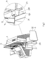
- the arrangement according to the invention for storing is essentially realized in the insert 2 coupled to the franking machine 1 and the storage box 3 connected to it.
- the insert 2 is designed as a one-piece part.
- a channel 211 running horizontally obliquely to the rear is formed, see also FIGS. 4 and 5.
- the angular storage box 3 has a front wall 31, a side wall 32 and a bottom plate 33 orthogonally to one another.
- the storage box 3 is guided with its front wall 31 in the transport direction and opposite to it adjustable in a slot 212 of the insert 2, see also Fig. 6. In this way, the distance from the side wall 32 to the exit of the franking machine 1 is the largest letter format to be processed adjustable.
- the letter 0 is conveyed in the franking machine 1 standing on one edge by means of a conveyor belt 12, sliding along a slightly inclined guide plate 11, and on the output side is pushed onto the channel 211 by means of a driven transport roller 14 arranged flush in the guide plane 121.
- the outgoing part of the guide level 121 is sloping, see also FIG. 5.
- the letter 0 can optionally stand on the conveyor belt 12, which is not shown in greater detail, or a short leg of the guide plate 11 during transport in the franking machine 1. Accordingly, the guide plane 121 for the lower edge of the letter is formed either by the upper surface of the conveyor belt 12 and a subsequent slide 121 or by the surface of the short leg of the guide plate 11.
- the insert 2 consists of a plastic, preferably of acrylonitrile-butadiene-styrene.
- the storage box 3 is expediently designed to be corrosion-resistant, for example in the form of a non-rusting metal or a metal-coated plastic - matt hard chrome-plated.
- the trough 211 runs horizontally in the franking machine 1 to match the standing level 121 of the letter 0.
- the groove 531 runs horizontally but slightly obliquely to the rear behind the front plane of the guide plate 11 in the transport direction.
- the letter 0 is clearly pre-oriented due to the inclination of the guide plate 11, so that storage in the direction of the storage box 3 is guaranteed, see also the explanations for FIG. 6.
- the letters 0 are stacked one above the other on the base plate 33 of the storage box 3.
- the right side wall 32 prevents the letters 0 from migrating sideways.
- the front wall 31 of the storage box 3 is adjustable in accordance with the largest letter format to be processed in the slot 212 of the front wall 21 of the insert 2 led, see also Fig. 6.
- the trough 211 has a nose 2110, which projects beyond the side of the insert 5 into the sloping area of the franking machine 1.
- the nose 2110 is designed as an inclined plane sloping outwards in order to prevent the letters 1 from getting caught when transitioning to the channel 211.
- the trough 211 has at the beginning in the rear region a support plate 2114 which is adapted to the inclination of the guide plate 11 in the franking machine 1. This support plate 2114 prevents thin, light letters 1 from fluttering and consequently not being properly deposited, see also FIG. 6.
- the channel 211 has a front upper guide slope 2111, a front lower guide slope 2112 and a rear guide slope 2113. In the cross profile there is a wedge-shaped depression that is bent on one side. A letter 0 entering the trough 211 slides down on the guide bevels 2111, 2112, 2113 as far as the bottom as the thickness of the attached letter edge allows.
- FIG. 6 shows the movement sequence of the letter 0 in the deposit from the insert 2 in the storage box 3 in more detail.
- the design of the trough 211 and the rear 213 of the front wall 21 have a particular influence.
- the rear 213 of the front wall 21 undercuts the groove 211 or the rear guide bevel 2113.
- the letter 0 has completely left the franking machine 1, it initially tilts over the rear guide bevel 2113, in order then to strike the bottom plate 33 of the storage box 3 or the previously deposited letter 01 at an oblique angle with the edge opposite the envelope flap 01.
- the letter 0 slides down with the edge of the envelope flap 01 on the rear 213 of the front wall 21. In this way, the letter 0 slides into the storage box 3 and shock loads are consequently avoided.
- the shelf becomes softer. Since the letter 0 is also guided horizontally in this due to the horizontal course of the channel 211, it tilts only over the upper edge of the rear guide bevel 2113. Accordingly, at least one stack height for the letters 0 is possible, which corresponds to the height of the upper edge mentioned.
Landscapes
- Devices For Checking Fares Or Tickets At Control Points (AREA)
- Separation, Sorting, Adjustment, Or Bending Of Sheets To Be Conveyed (AREA)
- Sorting Of Articles (AREA)
- Pile Receivers (AREA)
Abstract
Description
Der Einsatz 2 ist winkelförmig und besteht aus einer Vorderwand 21 und aus einer Seitenwand 22, wobei die Seitenwand 22 an die Frankiermaschine 1 angedockt ist und beide Wände 21, 22 zueinander orthogonal sind. Die Vorderwand 21 weist eine in Transportrichtung abfallende Rinne 211 auf, die an die Führungsebene 121 für die Briefunterkante in der Frankiermaschine 1 anschließt. Der Ausgangsteil der Führungsebene 121 ist dabei analog wie die Rinne 211 abfallend ausgeführt.
In Verbindung mit dem Einsatz 2 ist ein Ablagekasten 3 in Form eines zum Einsatz verstellbarer Winkelteils vorgesehen, der aus einer Vorderwand 31, einer Seitenwand 32 und einer Bodenplatte 33 besteht, die zueinander orthogonal angeordnet sind. Die Bodenplatte 33 dient dabei als Träger für die abgelegten Briefe 0. Die Vorderwand 31 ist in einem angepaßten Schlitz 212 der Vorderwand des Einsatzes 2 verstellbar geführt. Die Seitenwand 32 ist als federnde Prallwand ausgeführt, die mit einstellbarem Abstand nach der Rinne 211 und orthogonal zur Brieftransportrichtung angeordnet ist. Der Abstand ist in der Regel etwas größer gewählt als das größte zu verarbeitende Briefformat.
Da der Briefstapel mit als Kippkante wirkt, wird mit dieser Anordnung eine Stapelhöhe erreicht, die etwa der halben Höhe des kleinsten Briefformats beziehungsweise der Höhe des mittleren Teils der Rinne 211 entspricht.
Bei den vorstehend beschriebenen Lösungen besteht bei der Ablage frisch geschlossener - insbesondere dicker - Briefe die Gefahr, daß der Verschluß wieder aufspringt. Darüberhinaus ist die Stapelhöhe durch den Stapel selbst eingeschränkt.
Da die Rinne zum einen horizontal verläuft und zum anderen schräg hinter die Führungsebene der Führungsplatte der Frankiermaschine gezogen ist, werden einerseits die Briefe abgebremst und andererseits sofort nach Verlassen der Frankiermaschine abgekippt. Ein harter Aufprall auf die Seitenwand des Ablagekastens wird dadurch vermieden. Die maximale Stapelhöhe wird durch die Höhe der hinteren Oberkante der Rinne über dem Boden des Ablagekastens bestimmt. Durch die in die Gleitfläche der Frankiermaschine hineinragende Nase vor der Rinne wird ein sanfter Übergang der Briefe auf die Rinne ohne die Gefahr des Verhakens erreicht.
Neben der Führungsrinne hat die erfindungsgemäße Gestaltung der Rückseite der Vorderwand des Einsatzes wesentlichen Einfluß. Da die Rückseite der Vorderwand die Rinne unterschneidet, ist für den abkippenden Brief genügend freier Raum vorhanden, um unter einem schrägen Winkel auf den Boden des Ablagekastens beziehungsweise auf den zuvor abgelegten Brief aufzutreffen. Die Rückseite ist in den Fallvorgang außerdem noch insofern miteinbezogen, indem der Brief mit der bisher tragenden Kante an der Rückseite anliegend nach unten gleitet. Die Rückseite des Einsatzes und die Seitenwand des Ablagekastens verhindern dabei ein Herausdrehen des Briefes zur Seite und nach vorn.
Es zeigen:
- Fig. 1
- eine perspektivische Ansicht einer Frankiermaschine mit einer Anordnung zur Ablage von Briefen gemäß DE 197 42 893.2 von vorn rechts,
- Fig. 2
- eine perspektivische Ansicht einer Frankiermaschine mit einer Vorrichtung zur Übergabe von Briefen gemäß DE 198 40 917 C1 von rechts
- Fig. 3
- eine perspektivische Ansicht einer Frankiermaschin mit der erfindungsgemäßen Anordnung zur Ablage von Briefen von vorn rechts,
- Fig. 4
- eine perspektivische Ansicht einer Anordnung gemäß Fig. 3 von hinten links,
- Fig. 5
- eine Seitenansicht von rechts zu Fig. 3,
- Fig. 6
- Details zur Briefablage,
- a) von vorn rechts,
- b) von hinten links.
Der Einsatz 2 ist als einstückiges Teil ausgeführt. In die Vorderwand 21 ist eine horizontal schräg nach hinten verlaufende Rinne 211 eingeformt, siehe auch Fig. 4 und 5.
Der winkelförmige Ablagekasten 3 weist zueinander orthogonal eine Vorderwand 31, eine Seitenwand 32 und eine Bodenplatte 33 auf. Der Ablagekasten 3 ist mit seiner Vorderwand 31 in Transportrichtung und entgegen derselben verstellbar in einem Schlitz 212 des Einsatzes 2 geführt, siehe auch Fig. 6. Auf diese Weise ist der Abstand der Seitenwand 32 zum Ausgang der Frankiermaschine 1 auf das größte jeweils zu verarbeitende Briefformat einstellbar.
Der Einsatz 2 besteht aus einem Plast, vorzugsweise aus Acrylnitril-Butadien-Styrol.
Der Ablagekasten 3 ist zweckmäßigerweise korrosionsbeständig ausgeführt, beispielweise in Form eines nichtrostenden Metalls oder eines metallbeschichteten Plastes - matt hartverchromt -.
Die Rinne 211 verläuft horizontal in Anpassung an die Standebene 121 des Briefes 0 in der Frankiermaschine 1.
Der Brief 0 ist auf Grund der Neigung der Führungsplatte 11 eindeutig vororientiert, so daß eine Ablage in Richtung Ablagekasten 3 garantiert ist, siehe auch Ausführungen zu Fig. 6.
Die Briefe 0 liegen übereinandergestapelt auf der Bodenplatte 33 des Ablagekastens 3. Die rechte Seitenwand 32 verhindert ein seitliches Auswandern der Briefe 0. Die Vorderwand 31 des Ablagekastens 3 ist verstellbar entsprechend dem jeweils größten zu verarbeitenden Briefformat in dem Schlitz 212 der Vorderwand 21 des Einsatzes 2 geführt, siehe auch Fig. 6.
Am Anfang weist die Rinne 211 eine Nase 2110 auf, die über die Seite des Einsatzes 5 herausragt bis in den abfallenden Bereich der Frankiermaschine 1 hinein. Die Nase 2110 ist als nach außen abfallende schiefe Ebene ausgebildet, um ein Verhaken der Briefe 1 beim Übergang auf die Rinne 211 zu verhindern. Außerdem weist die Rinne 211 am Anfang im rückwärtigen Bereich eine Stützplatte 2114 auf, die der Neigung der Führungsplatte 11 in der Frankiermaschine 1 angepaßt ist. Mit dieser Stützplatte 2114 wird verhindert, daß dünne leichte Briefe 1 ins Flattern kommen und als Folge nicht ordnungsgemäß abgelegt werden, siehe gleichfalls Fig. 6.
Die Rinne 211 weist eine vordere obere Führungsschräge 2111, eine vordere untere Führungsschräge 2112 und eine hintere Führungsschräge 2113 auf. Im Querprofil ergibt sich eine einseitig abgeknickte keilförmige Vertiefung. Ein in die Rinne 211 einlaufender Brief 0 rutscht an den Führungsschrägen 2111, 2112, 2113 so weit zum Grund hinab, wie es die Dicke der aufsetzenden Briefkante gestattet.
Die Rückseite 213 der Vorderwand 21 unterschneidet die Rinne 211 beziehungsweise die hintere Führungsschräge 2113.
Wenn der Brief 0 die Frankiermaschine 1 vollständig verlassen hat, kippt dieser über die hintere Führungsschräge 2113 zunächst ab, um dann mit der der Umschlagklappe 01 gegenüberliegenden Kante unter einem schrägen Winkel auf die Bodenplatte 33 des Ablagekastens 3 beziehungsweise den vorher abgelegten Brief 01 aufzutreffen. Anschließend rutscht der Brief 0 mit der Kante der Umschlagklappe 01 an der Rückseite 213 der Vorderwand 21 nach unten.
Auf diese Weise gelangt der Brief 0 gleitend in den Ablagekasten 3 und Stoßbelastungen werden demzufolge vermieden. Mit steigender Stapelhöhe wird die Ablage sanfter.
Da der Brief 0 auf Grund des horizontalen Verlaufes der Rinne 211 gleichfalls horizontal in dieser geführt wird, kippt dieser nur über die Oberkante der hinteren Führungsschräge 2113 ab. Demzufolge ist mindestens eine Stapelhöhe für die Briefe 0 möglich, die der Höhe der genannten Oberkante entspricht.
- 0
- Brief, Briefumschlag, Druckträger
- 01
- Umschlagklappe des Briefes 1
- 02
- Tasche des Briefes 1
- 1
- Frankiermaschine
- 11
- Führungsplatte
- 12
- Transportebene, Transportband
- 121
- Führungsebene
- 2
- Einsatz
- 21
- Vorderwand des Einsatzes 2
- 22
- Seitenwand des Einsatzes 2
- 211
- Rinne in der Vorderwand 21
- 2110
- Nase der Rinne 211
- 2111
- vordere, obere Führungsschräge der Rinne 211
- 2112
- vordere, untere Führungsschräge der Rinne 211
- 2113
- hintere Führungsschräge der Rinne 211
- 2114
- Stützplatte am Anfang der Rinne 211
- 212
- Schlitz in der Vorderwand 21 zur Aufnahme der Vorderwand 31 des Ablagekastens 3
- 213
- Rückseite der Vorderwand 21
- 3
- Ablagekasten, Kasten
- 61
- Vorderwand des Ablagekastens 6
- 62
- Seitenwand des Ablagekastens 6
- 63
- Bodenplatte des Ablagekastens
Claims (7)
- Anordnung zur Ablage von Aufzeichnungsträgern, insbesondere Briefen, die in einer Frankier- und/oder Adressiermaschine auf einer Kante stehend und an einer geneigten Führungsplatte anliegend transportiert werden, dadurch gekennzeichnet,
daß ein einstückiger Einsatz (2) seitlich an die Frankiermaschine (1) angedockt ist, der eine Rinne (211) aufweist,
die an die Führungsebene (121) für die Briefunterkante in der Frankiermaschine (1) anschließt und in der die Briefe entlanggleiten,
die horizontal verläuft und leicht schräg nach hinten hinter die Anlageebene der Führungsplatte (11) geführt ist,
die so unterschnitten ist, daß der Ablagebereich bis unter die Rinne (211) erstreckt ist, und
daß in Verbindung mit dem Einsatz (2) ein Ablagekasten (3) vorgesehen ist. - Anordnung nach Anspruch 1, dadurch gekennzeichnet, daß die Rinne (211) in die Vorderwand (21) des Einsatzes eingeformt ist daß die Rückseite (213) der Vorderwand (21) die Rinne (211) unterschneidet,
daß eine Transportrolle (14) in dem der Rinne (211) vorangehenden Teil in der Frankiermaschine (1) bündig abschließend mit der Führungsebene (121) angeordnet ist und der nachfolgende Teil der Führungsebene (121) in der Frankiermaschine (1) abfallend ausgeführt ist. - Anordnung nach Anspruch 1 und 2, dadurch gekennzeichnet,
daß die Rinne (211) am Anfang eine Nase (2110) aufweist, die als schiefe Ebene abfallend zur Frankiermaschine (1) hin über die Seite des Einsatzes (2) herausragt bis in den abfallenden Teil der Führungsebene (121) hinein,
daß die Rinne (211) außerdem am Anfang im rückwärtigen Bereich eine Stützplatte (2114) aufweist, die der Neigung der Führungsplatte (11) in der Frankiermaschine (1) angepaßt ist,
daß die Rinne (211) eine vordere obere Führungsschräge (2111), eine vordere untere Führungsschräge (2112) und eine hintere Führungsschräge (2113) aufweist, so daß im Querprofil eine einseitig abgeknickte keilförmige Vertiefung vorliegt. - Anordnung nach Anspruch 1, dadurch gekennzeichnet, daß der Einsatz (2) aus einem Plast, vorzugsweise Acrylnitril-Butadien-Styrol, besteht.
- Anordnung nach Anspruch 1, dadurch gekennzeichnet, daß der Ablagekasten (3) winkelförmig ausgeführt und zu dem Einsatz (2) verstellbar angeordnet ist.
- Anordnung nach Anspruch 1 und 5, dadurch gekennzeichnet,
daß der Ablagekasten (3) aus einer Vorderwand (31), einer Seitenwand (32) und einer Bodenplatte (33) besteht, die zueinander orthogonal angeordnet sind, wobei die Bodenplatte (33) als Träger für die abgelegten Briefe (0) dient und die Vorderwand (31) in einem angepaßten Schlitz (212) in der Vorderwand (21) des Einsatzes (2) geführt ist,
daß die Seitenwand (32) mit einstellbarem Abstand nach der Rinne (211) und orthogonal zur Transportrichtung angeordnet ist, wobei der Abstand der Seitenwand (32) zum Ausgang der Frankiermaschine (1) etwas größer als das jeweils größte zu verarbeitende Briefformat eingestellt ist. - Anordnung nach Anspruch 1, dadurch gekennzeichnet, daß der Ablagekasten (3) korrosionsbeständig, wahlweise aus Metall oder Plast, ausgeführt ist.
Applications Claiming Priority (2)
| Application Number | Priority Date | Filing Date | Title |
|---|---|---|---|
| DE19900687A DE19900687B4 (de) | 1999-01-05 | 1999-01-05 | Anordnung zur Ablage von Aufzeichnungsträgern |
| DE19900687 | 1999-01-05 |
Publications (3)
| Publication Number | Publication Date |
|---|---|
| EP1018434A2 true EP1018434A2 (de) | 2000-07-12 |
| EP1018434A3 EP1018434A3 (de) | 2000-12-13 |
| EP1018434B1 EP1018434B1 (de) | 2006-03-01 |
Family
ID=7893929
Family Applications (1)
| Application Number | Title | Priority Date | Filing Date |
|---|---|---|---|
| EP99250399A Expired - Lifetime EP1018434B1 (de) | 1999-01-05 | 1999-11-12 | Anordnung zur Ablage von Aufzeichungsträgern |
Country Status (3)
| Country | Link |
|---|---|
| US (1) | US6280104B1 (de) |
| EP (1) | EP1018434B1 (de) |
| DE (2) | DE19900687B4 (de) |
Families Citing this family (6)
| Publication number | Priority date | Publication date | Assignee | Title |
|---|---|---|---|---|
| DE19840917C1 (de) * | 1998-09-08 | 2000-01-13 | Francotyp Postalia Gmbh | Vorrichtung zur Übergabe von Postgut an eine Ablagevorrichtung |
| EP1259449B1 (de) * | 2000-03-03 | 2005-09-14 | Ferag AG | Verfahren und vorrichtung zum ablegen flächiger erzeugnisse |
| US7828286B2 (en) * | 2005-11-10 | 2010-11-09 | Xerox Corporation | Automatic document scanner with upright visible document images |
| USD587301S1 (en) * | 2006-05-31 | 2009-02-24 | Francotyp - Postalia Gmbh | Franking system |
| USD596224S1 (en) * | 2006-05-31 | 2009-07-14 | Francotyp - Postalia Gmbh | Franking system |
| CA168408S (en) * | 2015-12-01 | 2017-04-13 | Francotyp Postalia Gmbh | Franking machine |
Citations (4)
| Publication number | Priority date | Publication date | Assignee | Title |
|---|---|---|---|---|
| DE19605015C1 (de) | 1996-01-31 | 1997-03-06 | Francotyp Postalia Gmbh | Vorrichtung zum Bedrucken eines auf einer Kante stehenden Druckträgers |
| DE19605014C1 (de) | 1996-01-31 | 1997-03-13 | Francotyp Postalia Gmbh | Vorrichtung zum Bedrucken eines auf einer Kante stehenden Druckträgers |
| DE19742893A1 (de) | 1997-09-24 | 1999-04-01 | Francotyp Postalia Gmbh | Anordnung zur Ablage von Aufzeichnungsträgern |
| DE19840917C1 (de) | 1998-09-08 | 2000-01-13 | Francotyp Postalia Gmbh | Vorrichtung zur Übergabe von Postgut an eine Ablagevorrichtung |
Family Cites Families (15)
| Publication number | Priority date | Publication date | Assignee | Title |
|---|---|---|---|---|
| JPS5093433A (de) * | 1973-12-19 | 1975-07-25 | ||
| US4561352A (en) * | 1984-11-05 | 1985-12-31 | Bell & Howell Company | Rotatable print mechanism for printing on front or back of media |
| GB2208369B (en) * | 1987-07-09 | 1991-07-03 | Alcatel Business Systems | Franking machine |
| US5233532A (en) * | 1991-04-10 | 1993-08-03 | U-Ship Usa, Ltd. | System for mailing and collecting items |
| US5332210A (en) * | 1992-11-18 | 1994-07-26 | Pitney Bowes Inc. | Variable size envelope drop stacker having means for assuring envelope sealing |
| US5464317A (en) * | 1992-11-18 | 1995-11-07 | Pitney Bowes Inc. | Registration power stacker |
| US5368287A (en) * | 1993-11-15 | 1994-11-29 | Pitney Bowes Inc. | Ninety degree turn-up apparatus |
| JP3371644B2 (ja) * | 1995-09-14 | 2003-01-27 | オムロン株式会社 | 郵便物処理システム、郵便物処理装置、読取装置およびホストコンピュータ |
| FR2758763B1 (fr) * | 1997-01-24 | 1999-04-16 | Neopost Ind | Machine compacte de traitement de courrier a chemin de transport particulier |
| DE19705089C1 (de) * | 1997-02-01 | 1998-03-26 | Francotyp Postalia Gmbh | Anordnung zur Ablage von Aufzeichnungsträgern |
| DE19711997A1 (de) * | 1997-03-13 | 1998-09-17 | Francotyp Postalia Gmbh | Anordnung zur Kommunikation zwischen einer Basisstation und weiteren Stationen einer Postbearbeitungsmaschine und zu deren Notabschaltung |
| US6041569A (en) * | 1997-07-11 | 2000-03-28 | Pitney Bowes Inc. | Mailing machine having envelope closing and sealing device |
| DE19740395A1 (de) * | 1997-09-05 | 1999-03-11 | Francotyp Postalia Gmbh | Vorrichtung zum Transport und zum Bedrucken von Druckträgern |
| DE19748954A1 (de) * | 1997-10-29 | 1999-05-06 | Francotyp Postalia Gmbh | Verfahren für eine digital druckende Frankiermaschine zur Erzeugung und Überprüfung eines Sicherheitsabdruckes |
| US6000774A (en) * | 1998-03-24 | 1999-12-14 | Pitney Bowes Inc. | Mailing machine including ink jet operation checking for prevention of loss of postal funds |
-
1999
- 1999-01-05 DE DE19900687A patent/DE19900687B4/de not_active Expired - Fee Related
- 1999-11-12 EP EP99250399A patent/EP1018434B1/de not_active Expired - Lifetime
- 1999-11-12 DE DE59913174T patent/DE59913174D1/de not_active Expired - Lifetime
-
2000
- 2000-01-05 US US09/477,889 patent/US6280104B1/en not_active Expired - Lifetime
Patent Citations (4)
| Publication number | Priority date | Publication date | Assignee | Title |
|---|---|---|---|---|
| DE19605015C1 (de) | 1996-01-31 | 1997-03-06 | Francotyp Postalia Gmbh | Vorrichtung zum Bedrucken eines auf einer Kante stehenden Druckträgers |
| DE19605014C1 (de) | 1996-01-31 | 1997-03-13 | Francotyp Postalia Gmbh | Vorrichtung zum Bedrucken eines auf einer Kante stehenden Druckträgers |
| DE19742893A1 (de) | 1997-09-24 | 1999-04-01 | Francotyp Postalia Gmbh | Anordnung zur Ablage von Aufzeichnungsträgern |
| DE19840917C1 (de) | 1998-09-08 | 2000-01-13 | Francotyp Postalia Gmbh | Vorrichtung zur Übergabe von Postgut an eine Ablagevorrichtung |
Also Published As
| Publication number | Publication date |
|---|---|
| EP1018434B1 (de) | 2006-03-01 |
| DE59913174D1 (de) | 2006-04-27 |
| DE19900687A1 (de) | 2000-07-06 |
| EP1018434A3 (de) | 2000-12-13 |
| US6280104B1 (en) | 2001-08-28 |
| DE19900687B4 (de) | 2005-09-15 |
Similar Documents
| Publication | Publication Date | Title |
|---|---|---|
| DE4416893C1 (de) | Leitvorrichtung für Verteilfördereinrichtung | |
| DE443076T1 (de) | Vereinzelnder spender mit vakuumfoerderbalken und methode zur vereinzelung von produkten. | |
| DE2459251A1 (de) | Vorrichtung zur ausgabe einzelner muenzen | |
| EP2120615A1 (de) | Entleermagazin für eine schragenentleereinrichtung zum entleeren von mit stabförmigen produkten gefüllten schrägen | |
| EP1018434A2 (de) | Anordnung zur Ablage von Aufzeichungsträgern | |
| DE10147134B4 (de) | Stackerriemen mit geschalteten Einzahlkassetten | |
| DE2929660A1 (de) | Vorrichtung zum zufuehren von aus einem schragen entnommenen zigaretten zu einer packmaschine o.dgl. | |
| EP1018442B1 (de) | Anordnung zum Schliessen von Briefumschlägen | |
| EP0465874A1 (de) | Speicher- und Stapeleinrichtung für flächig ausgebildete Teile | |
| EP0985619B1 (de) | Vorrichtung zur Übergabe von Postgut an eine Ablagevorrichtung | |
| DE10015756C2 (de) | Kuvertierstation | |
| DE4035397A1 (de) | Vorrichtung zum verpacken von zigaretten | |
| EP0121710B1 (de) | Einsatz für eine Kassenschublade | |
| DE1449005B2 (de) | ||
| EP3192757B1 (de) | Ablagevorrichtung für flache güter | |
| DE19705089C1 (de) | Anordnung zur Ablage von Aufzeichnungsträgern | |
| DE19742893A1 (de) | Anordnung zur Ablage von Aufzeichnungsträgern | |
| DE10050964A1 (de) | Vorrichtung zum Transport und zur Ablage von Einzelblättern | |
| DE3929656A1 (de) | Verfahren und vorrichtung zum lagern in und zum automatischen entnehmen von stueckgutsorten aus regalen in grosslagern | |
| DE4205775C2 (de) | Ablage an einem Drucker | |
| DE1574189C (de) | Magazin fur einen gestapelten Mun zenvorrat fur Selbstverkäufer | |
| DE911950C (de) | Einrichtung zur Aufbewahrung und Darreichung von Folien | |
| CH680201A5 (de) | ||
| DE2512896C3 (de) | Münzförderwerk mit einer Transportscheibe | |
| DE1449005C (de) | Einrichtung zum Sortieren von Post Sendungen nach ihrem Gewicht |
Legal Events
| Date | Code | Title | Description |
|---|---|---|---|
| PUAI | Public reference made under article 153(3) epc to a published international application that has entered the european phase |
Free format text: ORIGINAL CODE: 0009012 |
|
| AK | Designated contracting states |
Kind code of ref document: A2 Designated state(s): CH DE FR GB IT LI |
|
| AX | Request for extension of the european patent |
Free format text: AL;LT;LV;MK;RO;SI |
|
| PUAL | Search report despatched |
Free format text: ORIGINAL CODE: 0009013 |
|
| AK | Designated contracting states |
Kind code of ref document: A3 Designated state(s): AT BE CH CY DE DK ES FI FR GB GR IE IT LI LU MC NL PT SE |
|
| AX | Request for extension of the european patent |
Free format text: AL;LT;LV;MK;RO;SI |
|
| 17P | Request for examination filed |
Effective date: 20010412 |
|
| AKX | Designation fees paid |
Free format text: CH DE FR GB IT LI |
|
| RAP1 | Party data changed (applicant data changed or rights of an application transferred) |
Owner name: FRANCOTYP-POSTALIA AG & CO. KG |
|
| 17Q | First examination report despatched |
Effective date: 20040907 |
|
| GRAP | Despatch of communication of intention to grant a patent |
Free format text: ORIGINAL CODE: EPIDOSNIGR1 |
|
| GRAS | Grant fee paid |
Free format text: ORIGINAL CODE: EPIDOSNIGR3 |
|
| RAP1 | Party data changed (applicant data changed or rights of an application transferred) |
Owner name: FRANCOTYP-POSTALIA GMBH |
|
| GRAA | (expected) grant |
Free format text: ORIGINAL CODE: 0009210 |
|
| AK | Designated contracting states |
Kind code of ref document: B1 Designated state(s): CH DE FR GB IT LI |
|
| PG25 | Lapsed in a contracting state [announced via postgrant information from national office to epo] |
Ref country code: IT Free format text: LAPSE BECAUSE OF FAILURE TO SUBMIT A TRANSLATION OF THE DESCRIPTION OR TO PAY THE FEE WITHIN THE PRESCRIBED TIME-LIMIT;WARNING: LAPSES OF ITALIAN PATENTS WITH EFFECTIVE DATE BEFORE 2007 MAY HAVE OCCURRED AT ANY TIME BEFORE 2007. THE CORRECT EFFECTIVE DATE MAY BE DIFFERENT FROM THE ONE RECORDED. Effective date: 20060301 |
|
| REG | Reference to a national code |
Ref country code: GB Ref legal event code: FG4D Free format text: NOT ENGLISH |
|
| REG | Reference to a national code |
Ref country code: CH Ref legal event code: NV Representative=s name: ROTTMANN, ZIMMERMANN + PARTNER AG Ref country code: CH Ref legal event code: EP |
|
| REF | Corresponds to: |
Ref document number: 59913174 Country of ref document: DE Date of ref document: 20060427 Kind code of ref document: P |
|
| GBT | Gb: translation of ep patent filed (gb section 77(6)(a)/1977) |
Effective date: 20060426 |
|
| ET | Fr: translation filed | ||
| PLBE | No opposition filed within time limit |
Free format text: ORIGINAL CODE: 0009261 |
|
| STAA | Information on the status of an ep patent application or granted ep patent |
Free format text: STATUS: NO OPPOSITION FILED WITHIN TIME LIMIT |
|
| 26N | No opposition filed |
Effective date: 20061204 |
|
| REG | Reference to a national code |
Ref country code: CH Ref legal event code: PFA Owner name: FRANCOTYP-POSTALIA GMBH Free format text: FRANCOTYP-POSTALIA GMBH#TRIFTWEG 21-26#16547 BIRKENWERDER (DE) -TRANSFER TO- FRANCOTYP-POSTALIA GMBH#TRIFTWEG 21-26#16547 BIRKENWERDER (DE) |
|
| PGFP | Annual fee paid to national office [announced via postgrant information from national office to epo] |
Ref country code: CH Payment date: 20121122 Year of fee payment: 14 Ref country code: FR Payment date: 20121130 Year of fee payment: 14 Ref country code: DE Payment date: 20120908 Year of fee payment: 14 |
|
| PGFP | Annual fee paid to national office [announced via postgrant information from national office to epo] |
Ref country code: IT Payment date: 20121126 Year of fee payment: 14 Ref country code: GB Payment date: 20121120 Year of fee payment: 14 |
|
| REG | Reference to a national code |
Ref country code: CH Ref legal event code: PL |
|
| GBPC | Gb: european patent ceased through non-payment of renewal fee |
Effective date: 20131112 |
|
| PG25 | Lapsed in a contracting state [announced via postgrant information from national office to epo] |
Ref country code: CH Free format text: LAPSE BECAUSE OF NON-PAYMENT OF DUE FEES Effective date: 20131130 Ref country code: LI Free format text: LAPSE BECAUSE OF NON-PAYMENT OF DUE FEES Effective date: 20131130 |
|
| REG | Reference to a national code |
Ref country code: FR Ref legal event code: ST Effective date: 20140731 |
|
| REG | Reference to a national code |
Ref country code: DE Ref legal event code: R119 Ref document number: 59913174 Country of ref document: DE Effective date: 20140603 |
|
| PG25 | Lapsed in a contracting state [announced via postgrant information from national office to epo] |
Ref country code: DE Free format text: LAPSE BECAUSE OF NON-PAYMENT OF DUE FEES Effective date: 20140603 Ref country code: IT Free format text: LAPSE BECAUSE OF NON-PAYMENT OF DUE FEES Effective date: 20131112 |
|
| PG25 | Lapsed in a contracting state [announced via postgrant information from national office to epo] |
Ref country code: FR Free format text: LAPSE BECAUSE OF NON-PAYMENT OF DUE FEES Effective date: 20131202 Ref country code: GB Free format text: LAPSE BECAUSE OF NON-PAYMENT OF DUE FEES Effective date: 20131112 |