EP1018617A2 - Dichtring für eine Steckmuffenverbindung - Google Patents
Dichtring für eine Steckmuffenverbindung Download PDFInfo
- Publication number
- EP1018617A2 EP1018617A2 EP99126267A EP99126267A EP1018617A2 EP 1018617 A2 EP1018617 A2 EP 1018617A2 EP 99126267 A EP99126267 A EP 99126267A EP 99126267 A EP99126267 A EP 99126267A EP 1018617 A2 EP1018617 A2 EP 1018617A2
- Authority
- EP
- European Patent Office
- Prior art keywords
- sealing ring
- seal
- pipe
- sealing
- lip
- Prior art date
- Legal status (The legal status is an assumption and is not a legal conclusion. Google has not performed a legal analysis and makes no representation as to the accuracy of the status listed.)
- Granted
Links
- 238000007789 sealing Methods 0.000 title claims abstract description 59
- 239000011324 bead Substances 0.000 claims description 12
- 230000003014 reinforcing effect Effects 0.000 claims description 11
- 230000002787 reinforcement Effects 0.000 abstract description 12
- 230000000694 effects Effects 0.000 description 6
- 230000008719 thickening Effects 0.000 description 5
- 244000089486 Phragmites australis subsp australis Species 0.000 description 3
- 230000006835 compression Effects 0.000 description 3
- 238000007906 compression Methods 0.000 description 3
- 238000011109 contamination Methods 0.000 description 3
- 229910000831 Steel Inorganic materials 0.000 description 2
- 238000003780 insertion Methods 0.000 description 2
- 230000037431 insertion Effects 0.000 description 2
- 239000010959 steel Substances 0.000 description 2
- 238000010276 construction Methods 0.000 description 1
- 238000011161 development Methods 0.000 description 1
- 230000018109 developmental process Effects 0.000 description 1
- 238000004519 manufacturing process Methods 0.000 description 1
- 230000002093 peripheral effect Effects 0.000 description 1
- 239000010865 sewage Substances 0.000 description 1
Images


Classifications
-
- F—MECHANICAL ENGINEERING; LIGHTING; HEATING; WEAPONS; BLASTING
- F16—ENGINEERING ELEMENTS AND UNITS; GENERAL MEASURES FOR PRODUCING AND MAINTAINING EFFECTIVE FUNCTIONING OF MACHINES OR INSTALLATIONS; THERMAL INSULATION IN GENERAL
- F16L—PIPES; JOINTS OR FITTINGS FOR PIPES; SUPPORTS FOR PIPES, CABLES OR PROTECTIVE TUBING; MEANS FOR THERMAL INSULATION IN GENERAL
- F16L21/00—Joints with sleeve or socket
- F16L21/02—Joints with sleeve or socket with elastic sealing rings between pipe and sleeve or between pipe and socket, e.g. with rolling or other prefabricated profiled rings
- F16L21/03—Joints with sleeve or socket with elastic sealing rings between pipe and sleeve or between pipe and socket, e.g. with rolling or other prefabricated profiled rings placed in the socket before connection
-
- F—MECHANICAL ENGINEERING; LIGHTING; HEATING; WEAPONS; BLASTING
- F16—ENGINEERING ELEMENTS AND UNITS; GENERAL MEASURES FOR PRODUCING AND MAINTAINING EFFECTIVE FUNCTIONING OF MACHINES OR INSTALLATIONS; THERMAL INSULATION IN GENERAL
- F16L—PIPES; JOINTS OR FITTINGS FOR PIPES; SUPPORTS FOR PIPES, CABLES OR PROTECTIVE TUBING; MEANS FOR THERMAL INSULATION IN GENERAL
- F16L17/00—Joints with packing adapted to sealing by fluid pressure
- F16L17/02—Joints with packing adapted to sealing by fluid pressure with sealing rings arranged between outer surface of pipe and inner surface of sleeve or socket
- F16L17/025—Joints with packing adapted to sealing by fluid pressure with sealing rings arranged between outer surface of pipe and inner surface of sleeve or socket the sealing rings having radially directed ribs
Definitions
- the invention relates to a sealing ring for a push-in joint a reinforcing ring according to the preamble of claim 1.
- Sealing rings of this type are normally used to connect two pipes, such as plastic sewage pipes, used in the ring beads of the sleeve end a tube can be used. If the tip end of a second pipe is in the sealing end of the first pipe is inserted, the sealing lips the seal close to the tube to be inserted, so that usually the Sealing is guaranteed.
- the seal has only one only sealing lip on the tip of a pipe to be inserted is present. There is therefore a risk that possible contamination of the Lip seal lead to a leak in the pipe connection. Furthermore results when deflecting the lip seal due to the insertion Sharp wedging of the base of the lip on one edge of the Reinforcement ring, so that easily the risk of damage to the Lip seal exists.
- the invention has for its object a sealing ring for a Specify push-in joint with inserted reinforcement ring by on the one hand an improved sealing effect of those to be assembled Tubes guaranteed and on the other hand a high pressure force of the seal is achievable.
- a sealing ring for a push-in socket connection indicated, in a substantially rectangular cross-section annular bead the socket end of a pipe end can be used and a rotating one Contains reinforcement ring which in an inwardly open recess of the Sealing ring is included, the sealing ring on the front one has angled lip seal and a at the rear end Pressure seal contains.
- the rear has Pressure seal a front, obliquely to the radial plane of the tube to the rear inclined ramp surface, over which when inserting the tip end second pipe in the sleeve, the pressure seal for contact with the spigot of the second tube through the deflected lip seal backwards and is deflected inwards towards the tube axis.
- the measures according to the invention can be achieved that the lip seal deflected by the tip end of the pipe to be inserted comes to the system on the contact surface of the pressure seal and with further Push in the pipe the pressure seal in the push back direction presses and squeezes at the same time.
- the sealing function remains Lip seal preserved on the one hand, but on the other hand also a sealing function the pressure seal can be reached.
- the run-up surface is oblique to the radial plane of the pipe towards the rear / inside inclined so that the lip seal impinging on the run-up surface Increasing the pressure glides over the ramp surface and thus the Pressure seal deformed in the direction of insertion of the tip end.
- the pressure seal preferably projects beyond the reinforcing ring in its Starting position in a partial area. This allows the design of the Shorten the seal. In the assembled state of the pipes Pressure seal, however, deflected so far that it does not reinforce the ring more towering, but the space above the reinforcement ring from the Lip seal is taken.
- the sealing ring has on its outside in the bead base preferably several peripheral web-like projections. These are in yours Height designed so that even when two pipes are assembled Between the projections there is space between the sealing back and the ribbed base remain.
- the sealing ring therefore remains compressible in this area, too that it can be used for large tolerance ranges of pipe systems.
- the Protrusions are preferably trapezoidal in cross section and are through arcuate recesses on the outside of the seal connected.
- the seal shown in FIG. 1 is in an annular bead 16 Socket end 9 of a first tube used. It contains one made of plastic or steel existing reinforcement ring 6, the inner bevel or Rounds 4 and 11 contains.
- the reinforcement ring is in one Recess of the seal, which essentially towards the inside of the radius Lip seal 1 and the pressure seal 5 is covered.
- Fig. 1 shows the Seal in the relaxed state. If in this state the distance between the lip 12 of the lip seal 1 and the lip 2 of the Pressure seal 5 is reduced to almost zero, can be achieved that the Space of the seal in which the reinforcing ring 6 is arranged against Contamination of the seal in the unloaded state is largely secured.
- the lip seal 1 extends from the front end of the seal diagonally to the rear and becomes when inserting the tip end 13 of a second Tube 10 deflected over the lip flank 14 to the outside.
- the located between the projections 8 Free spaces 7 form a compression space when the pipes are plugged together. These free spaces 7 remain partially in the assembled state of the Pipes received so that a large tolerance range of pipes to be put together to be able to record.
- the pressure seal 5 arranged on the back of the sealing ring has a sloping rearward / inward running surface 15 on the Lip seal opposite side. Therefore, if the spiked end 13 a second tube 10 strikes the lip flank 14 of the lip seal 1, the lip 12 of the lip seal 1 on the run-up surface 15 of the Pressure seal 5 is pressed and slides along the run-up surface 15 inside, so that the pressure seal 5 is deflected to the rear and therefore rears up to the inside of the radius.
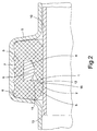
- Fig. 2 shows the corresponding state of a sealing ring inserted tip end 13 of a second tube 10 into the first tube 9. It it can be clearly seen that the lip 12 on the ramp surface 15 of the Pressure seal 5 has come to rest and this to the back has deflected. However, the pressure seal 5 rears inwards canceled again by the tube 10 by compressing the pressure seal 5 becomes. This ensures that on the one hand the lip seal 1 completely on the Pipe outside of the pipe 10 comes to rest and in particular the lip 12 their sealing function fulfills that the lip 12 by pressing against the Pressure seal 5 is increased in its pressure force that the lip 2 of the Pressure seal 5 exerts an additional sealing effect and the compression the pressure seal 5 additionally increases the sealing effect of the lip 2.
- Fig. 2 also clearly shows that the lip seal 1 has no wedge effect the reinforcing ring 6 experiences, but evenly around the chamfer 4 of the Reinforcement ring 6 runs around.
- the rear chamfer of the reinforcement ring 6 is irrelevant when the pipes are assembled.
- the condition of the seal can serve to increase the volume of the Pressure seal 5 to be able to enlarge without an extension of Seal is required.
- FIG. 3 shows a further embodiment of the invention a seal with an additional front wiper lip 17.
- the area of Scraper lip 17 is located in the area of a step 19 accordingly equipped sleeve 18.
- This area of a seal is already from the DE-GM 29 810 672 known.
- the basic principle of the seal according to the invention is but can also be used with this item.
Landscapes
- Engineering & Computer Science (AREA)
- General Engineering & Computer Science (AREA)
- Mechanical Engineering (AREA)
- Physics & Mathematics (AREA)
- Fluid Mechanics (AREA)
- Joints With Sleeves (AREA)
- Gasket Seals (AREA)
- Adhesives Or Adhesive Processes (AREA)
- Non-Disconnectible Joints And Screw-Threaded Joints (AREA)
- Adhesive Tapes (AREA)
- Closures For Containers (AREA)
- Flanged Joints, Insulating Joints, And Other Joints (AREA)
- Coupling Device And Connection With Printed Circuit (AREA)
- Insulating Bodies (AREA)
Abstract
Description
- Fig. 1
- eine Querschnittsansicht eines erfindungsgemäßen Dichtrings, der in einer Ringsicke eines Muffenendes eines Rohres eingesetzt ist im entlasteten Zustand,
- Fig. 2
- einen erfindungsgemäßen Dichtring in einer Ringsicke, bei dem das Spitzende eines zweiten Rohres in das Muffenende des die Dichtung aufnehmenden Rohres eingesteckt ist, und
- Fig. 3
- ein weiteres Ausführungsbeispiel der Erfindung.
- 1
- Lippendichtung
- 2
- Lippe
- 3
- Dichtrücken
- 4
- Fase
- 5
- Andruckdichtung
- 6
- Verstärkungsring
- 7
- Freiraum
- 8
- Vorsprung
- 9
- Muffenende
- 10
- zweites Rohr
- 11
- Fase
- 12
- Lippe
- 13
- Spitzende
- 14
- Lippenflanke
- 15
- Auflauffläche
- 16
- Sicke
- 17
- Abstreiflippe
- 18
- Muffe
- 19
- Stufe
Claims (9)
- Dichtring für eine Steckmuffenverbindung, der in eine im Querschnitt im wesentlichen rechteckige Ringsicke (16) des Muffenendes (9) eines Rohrendes einsetzbar ist, und einen umlaufenden Verstärkungsring (6) enthält, der in einer nach innen offenen Ausnehmung des Dichtrings aufgenommen ist, wobei der Dichtring an seinem Vorderende eine zum rückwärtigen Ende hin angewinkelte Lippendichtung (1) aufweist und am rückwärtigen Ende eine Andruckdichtung (5) enthält, dadurch gekennzeichnet, daß die rückwärtige Andruckdichtung (5) eine vordere schräg zur Radialebene des Rohres nach hinten geneigte Auflauffläche (15) aufweist, über die bei Einschieben des Spitzendes (13) eines zweiten Rohres (10) in die Muffe die Andruckdichtung (5) zur Anlage an das Spitzende des zweiten Rohres durch die abgelenkte Lippendichtung nach rückwärts und nach innen zur Rohrachse hin ausgelenkt wird.
- Dichtring nach Anspruch 1, dadurch gekennzeichnet, daß die Andruckdichtung (5) den Verstärkungsring (6) in einem Teilbereich überragt.
- Dichtring nach einem der Ansprüche 1 oder 2, dadurch gekennzeichnet, daß der Verstärkungsring (6) an seiner an die Lippendichtung (1) angrenzenden Seite eine Fase (4) oder Abrundung aufweist.
- Dichtring nach einem der Ansprüche 1 - 3, dadurch gekennzeichnet, daß der Verstärkungsring (6) an seiner an die Andruckdichtung angrenzende Seite eine innere Fase (11) oder Abrundung aufweist.
- Dichtring nach einem der vorhergehenden Ansprüche, dadurch gekennzeichnet, daß der Dichtring an seiner im Sickengrund anliegenden Außenseite mehrere umlaufende Vorsprünge (8) aufweist.
- Dichtring nach Anspruch 5, dadurch gekennzeichnet, daß die Vorsprünge (8) eine derartige Höhe gegenüber dem Dichtrücken (3) aufweisen, daß auch im zusammengesteckten Zustand zweier Rohre zwischen den Vorsprüngen (8) Freiräume (7) zwischen Dichtrücken (3) und dem Sickengrund verbleiben.
- Dichtring nach Anspruch 1, dadurch gekennzeichnet, daß die Vorsprünge (8) im Querschnitt trapezförmig gestaltet sind.
- Dichtring nach einem oder mehreren der vorhergehenden Ansprüche, dadurch gekennzeichnet, daß das Verhältnis zwischen Dichtringbreite und Dichtringdicke zwischen 2 : 1 und 4 : 1 beträgt.
- Dichtring nach Anspruch 8, dadurch gekennzeichnet, daß das Verhältnis zwischen Dichtringbreite und Dichtringdicke 3 : 1 beträgt.
Priority Applications (2)
| Application Number | Priority Date | Filing Date | Title |
|---|---|---|---|
| SI9930689T SI1018617T1 (en) | 1999-01-07 | 1999-12-31 | Sealing ring for a socket joint |
| DK99126267T DK1018617T3 (da) | 1999-01-07 | 1999-12-31 | Tætningsring til en stikmuffeforbindelse |
Applications Claiming Priority (2)
| Application Number | Priority Date | Filing Date | Title |
|---|---|---|---|
| DE19900302A DE19900302B4 (de) | 1999-01-07 | 1999-01-07 | Dichtring für eine Steckmuffenverbindung |
| DE19900302 | 1999-01-07 |
Publications (3)
| Publication Number | Publication Date |
|---|---|
| EP1018617A2 true EP1018617A2 (de) | 2000-07-12 |
| EP1018617A3 EP1018617A3 (de) | 2002-11-13 |
| EP1018617B1 EP1018617B1 (de) | 2004-11-03 |
Family
ID=7893696
Family Applications (1)
| Application Number | Title | Priority Date | Filing Date |
|---|---|---|---|
| EP99126267A Expired - Lifetime EP1018617B1 (de) | 1999-01-07 | 1999-12-31 | Dichtring für eine Steckmuffenverbindung |
Country Status (11)
| Country | Link |
|---|---|
| EP (1) | EP1018617B1 (de) |
| AT (1) | ATE281622T1 (de) |
| CZ (1) | CZ294528B6 (de) |
| DE (2) | DE19900302B4 (de) |
| DK (1) | DK1018617T3 (de) |
| ES (1) | ES2232997T3 (de) |
| HU (1) | HU222674B1 (de) |
| PL (1) | PL192326B1 (de) |
| PT (1) | PT1018617E (de) |
| RU (1) | RU2176350C2 (de) |
| SI (1) | SI1018617T1 (de) |
Cited By (3)
| Publication number | Priority date | Publication date | Assignee | Title |
|---|---|---|---|---|
| CN112413123A (zh) * | 2019-08-22 | 2021-02-26 | 西克股份公司 | 具有环形成型密封件的过程连接件 |
| CN117122789A (zh) * | 2023-09-11 | 2023-11-28 | 北京五瑞美阳医疗器械有限责任公司 | 湿化器及呼吸装置 |
| WO2023231847A1 (zh) * | 2022-06-02 | 2023-12-07 | 郝百顺 | 密封圈 |
Families Citing this family (5)
| Publication number | Priority date | Publication date | Assignee | Title |
|---|---|---|---|---|
| DE19949864C1 (de) | 1999-10-15 | 2001-06-28 | Mol Gummiverarbeitung | Dichtring für eine Steckmuffenverbindung zweier Rohre |
| DE10033096A1 (de) | 2000-07-07 | 2002-02-14 | Mol Gummiverarbeitung | Dichtungsring für eine Steckmuffenrohrverbindung |
| DE10219865B4 (de) * | 2002-05-03 | 2005-03-31 | M.O.L. Gummiverarbeitung Gmbh & Co. Kg | Dichtring für eine Steckmuffenverbindung |
| RU2351822C2 (ru) * | 2007-04-09 | 2009-04-10 | ОАО "Пластик" | Кольцо уплотнительное |
| RU2351823C2 (ru) * | 2007-04-09 | 2009-04-10 | ОАО "Пластик" | Фасонное уплотнение |
Citations (2)
| Publication number | Priority date | Publication date | Assignee | Title |
|---|---|---|---|---|
| EP0451900B1 (de) | 1990-04-12 | 1993-09-22 | Nyloplast Europe B.V. | Dichtungsring für eine Rohrverbindung |
| DE19713329A1 (de) | 1997-03-29 | 1998-10-01 | Bode Gmbh | Dichtring für Steckmuffenverbindungen |
Family Cites Families (8)
| Publication number | Priority date | Publication date | Assignee | Title |
|---|---|---|---|---|
| DE7118924U (de) * | 1971-09-23 | Arne E | Dichtung, insbesondere Gummiring dichtung fur Rohrverbindungen | |
| GB2016630B (en) * | 1978-02-03 | 1982-05-19 | Wavin Bv | Sealing of spigot and socket pipe joints |
| DE3226875C2 (de) * | 1982-07-17 | 1984-09-06 | Wavin B.V., Zwolle | Dichtungsring |
| DE8333286U1 (de) * | 1983-11-19 | 1984-03-08 | Gebr. Ostendorf oHG, 2848 Vechta | Dichtring zum einsetzen in die rohrmuffe eines rohres, insbesondere kunststoff-abwasserrohres |
| US4602792A (en) * | 1984-10-09 | 1986-07-29 | Polymer/Raymond Industries | Dual function gasket with dual lips and optional locking ring |
| CH666949A5 (de) * | 1985-08-09 | 1988-08-31 | Immanuel Straub | Rohrkupplung. |
| SE8505802D0 (sv) * | 1985-12-09 | 1985-12-09 | Forsheda Ab | Tetningsring |
| DE29810672U1 (de) * | 1998-06-13 | 1998-09-10 | UPONOR Hausabflußtechnik GmbH, 49685 Emstek | Rohr mit einer Ringsicke zur Aufnahme einer Ringdichtung |
-
1999
- 1999-01-07 DE DE19900302A patent/DE19900302B4/de not_active Expired - Fee Related
- 1999-12-31 DE DE59910985T patent/DE59910985D1/de not_active Expired - Lifetime
- 1999-12-31 SI SI9930689T patent/SI1018617T1/xx unknown
- 1999-12-31 PT PT99126267T patent/PT1018617E/pt unknown
- 1999-12-31 EP EP99126267A patent/EP1018617B1/de not_active Expired - Lifetime
- 1999-12-31 DK DK99126267T patent/DK1018617T3/da active
- 1999-12-31 ES ES99126267T patent/ES2232997T3/es not_active Expired - Lifetime
- 1999-12-31 AT AT99126267T patent/ATE281622T1/de not_active IP Right Cessation
-
2000
- 2000-01-04 CZ CZ20008A patent/CZ294528B6/cs not_active IP Right Cessation
- 2000-01-05 PL PL337681A patent/PL192326B1/pl not_active IP Right Cessation
- 2000-01-06 RU RU2000100461/06A patent/RU2176350C2/ru not_active IP Right Cessation
- 2000-01-06 HU HU0000024A patent/HU222674B1/hu not_active IP Right Cessation
Patent Citations (2)
| Publication number | Priority date | Publication date | Assignee | Title |
|---|---|---|---|---|
| EP0451900B1 (de) | 1990-04-12 | 1993-09-22 | Nyloplast Europe B.V. | Dichtungsring für eine Rohrverbindung |
| DE19713329A1 (de) | 1997-03-29 | 1998-10-01 | Bode Gmbh | Dichtring für Steckmuffenverbindungen |
Cited By (4)
| Publication number | Priority date | Publication date | Assignee | Title |
|---|---|---|---|---|
| CN112413123A (zh) * | 2019-08-22 | 2021-02-26 | 西克股份公司 | 具有环形成型密封件的过程连接件 |
| US11892079B2 (en) | 2019-08-22 | 2024-02-06 | Sick Ag | Process connection having an annular gasket |
| WO2023231847A1 (zh) * | 2022-06-02 | 2023-12-07 | 郝百顺 | 密封圈 |
| CN117122789A (zh) * | 2023-09-11 | 2023-11-28 | 北京五瑞美阳医疗器械有限责任公司 | 湿化器及呼吸装置 |
Also Published As
| Publication number | Publication date |
|---|---|
| HUP0000024A1 (hu) | 2000-12-28 |
| CZ294528B6 (cs) | 2005-01-12 |
| PL192326B1 (pl) | 2006-10-31 |
| PT1018617E (pt) | 2005-01-31 |
| ATE281622T1 (de) | 2004-11-15 |
| ES2232997T3 (es) | 2005-06-01 |
| DK1018617T3 (da) | 2005-01-31 |
| CZ20008A3 (cs) | 2000-11-15 |
| RU2176350C2 (ru) | 2001-11-27 |
| DE59910985D1 (de) | 2004-12-09 |
| DE19900302A1 (de) | 2001-08-09 |
| EP1018617B1 (de) | 2004-11-03 |
| EP1018617A3 (de) | 2002-11-13 |
| HU0000024D0 (en) | 2000-03-28 |
| DE19900302B4 (de) | 2005-11-17 |
| PL337681A1 (en) | 2000-07-17 |
| SI1018617T1 (en) | 2005-02-28 |
| HU222674B1 (hu) | 2003-09-29 |
Similar Documents
| Publication | Publication Date | Title |
|---|---|---|
| EP0087557B1 (de) | Rohrverbindung für Metallrohre | |
| EP0012166B1 (de) | Dichtungsring aus gummielastischem Werkstoff für Rippenrohre, insbesondere aus Kunststoff | |
| DE3644834C1 (de) | Rohrverbinder aus Muffe und Einsteckteil | |
| EP1143183A2 (de) | Dichtungsring für Verbindung zwischen Spitzende eines Wellrohres und Rohrmuffe mit glatter Innenwand | |
| EP0231446A1 (de) | Kunststoff-Wellrohr mit angeformter Steck-Muffe | |
| DE4122455A1 (de) | Steckverbindung fuer thermoplastische rohre | |
| DE3120266A1 (de) | Dichtring | |
| EP1636521B1 (de) | Verbindungseinrichtung für ein rohr oder dgl | |
| EP1018617B1 (de) | Dichtring für eine Steckmuffenverbindung | |
| DE60022079T2 (de) | Dichtung | |
| EP1092906A1 (de) | Dichtungsring für ein mit äusseren Wellen versehenes Kunststoffrohr | |
| EP0596230A1 (de) | Steckverbindung von Rohrstücken | |
| DE10219865B4 (de) | Dichtring für eine Steckmuffenverbindung | |
| DE19949864C1 (de) | Dichtring für eine Steckmuffenverbindung zweier Rohre | |
| DE19635053C2 (de) | Schlaucharmatur für Druckschläuche | |
| EP2667074B1 (de) | System mit Klemmteil zur Steckverbindung von Rohren | |
| WO1997025562A1 (de) | Vorrichtung und verfahren zur herstellung einer unlösbaren leitungsrohrverbindung | |
| DE585377C (de) | Gas- und fluessigkeitsdichte Flanschverbindung fuer Rohre | |
| WO1994011666A1 (de) | Steckmuffenverbindung | |
| WO1994005944A1 (de) | Abdichtung zwischen zwei ineinandersteckbaren teilen | |
| EP1170538A2 (de) | Dichtungsring für eine Steckmuffenrohrverbindung | |
| EP0967426A2 (de) | Dichtungsring zum Einsetzen in eine Sicke einer Rohrmuffe | |
| EP1479961A1 (de) | Pressfitting | |
| DE9419865U1 (de) | Übergangsrohrverbindung | |
| DE202020105499U1 (de) | Dichtring für eine Rohrverbindung |
Legal Events
| Date | Code | Title | Description |
|---|---|---|---|
| PUAI | Public reference made under article 153(3) epc to a published international application that has entered the european phase |
Free format text: ORIGINAL CODE: 0009012 |
|
| AK | Designated contracting states |
Kind code of ref document: A2 Designated state(s): AT BE CH CY DE DK ES FI FR GB GR IE IT LI LU MC NL PT SE |
|
| AX | Request for extension of the european patent |
Free format text: AL;LT;LV;MK;RO;SI |
|
| PUAL | Search report despatched |
Free format text: ORIGINAL CODE: 0009013 |
|
| AK | Designated contracting states |
Kind code of ref document: A3 Designated state(s): AT BE CH CY DE DK ES FI FR GB GR IE IT LI LU MC NL PT SE |
|
| AX | Request for extension of the european patent |
Free format text: AL;LT;LV;MK;RO;SI |
|
| RIC1 | Information provided on ipc code assigned before grant |
Free format text: 7F 16L 17/025 A, 7F 16L 21/03 B, 7F 16L 47/06 B |
|
| 17P | Request for examination filed |
Effective date: 20021231 |
|
| AKX | Designation fees paid |
Designated state(s): AT BE CH CY DE DK ES FI FR GB GR IE IT LI LU MC NL PT SE |
|
| AXX | Extension fees paid |
Extension state: SI Payment date: 20021231 Extension state: RO Payment date: 20021231 Extension state: MK Payment date: 20021231 Extension state: LV Payment date: 20021231 Extension state: LT Payment date: 20021231 Extension state: AL Payment date: 20021231 |
|
| GRAP | Despatch of communication of intention to grant a patent |
Free format text: ORIGINAL CODE: EPIDOSNIGR1 |
|
| GRAS | Grant fee paid |
Free format text: ORIGINAL CODE: EPIDOSNIGR3 |
|
| GRAA | (expected) grant |
Free format text: ORIGINAL CODE: 0009210 |
|
| AK | Designated contracting states |
Kind code of ref document: B1 Designated state(s): AT BE CH CY DE DK ES FI FR GB GR IE IT LI LU MC NL PT SE |
|
| AX | Request for extension of the european patent |
Extension state: AL LT LV MK RO SI |
|
| REG | Reference to a national code |
Ref country code: GB Ref legal event code: FG4D Free format text: NOT ENGLISH |
|
| REG | Reference to a national code |
Ref country code: CH Ref legal event code: EP |
|
| PGFP | Annual fee paid to national office [announced via postgrant information from national office to epo] |
Ref country code: MC Payment date: 20041117 Year of fee payment: 6 |
|
| REF | Corresponds to: |
Ref document number: 59910985 Country of ref document: DE Date of ref document: 20041209 Kind code of ref document: P |
|
| REG | Reference to a national code |
Ref country code: IE Ref legal event code: FG4D Free format text: GERMAN |
|
| PGFP | Annual fee paid to national office [announced via postgrant information from national office to epo] |
Ref country code: CY Payment date: 20050117 Year of fee payment: 6 |
|
| REG | Reference to a national code |
Ref country code: DK Ref legal event code: T3 Ref country code: PT Ref legal event code: SC4A Effective date: 20041122 Ref country code: CH Ref legal event code: NV Representative=s name: R. A. EGLI & CO. PATENTANWAELTE |
|
| GBT | Gb: translation of ep patent filed (gb section 77(6)(a)/1977) |
Effective date: 20050118 |
|
| REG | Reference to a national code |
Ref country code: SE Ref legal event code: TRGR |
|
| REG | Reference to a national code |
Ref country code: GR Ref legal event code: EP Ref document number: 20050400374 Country of ref document: GR |
|
| REG | Reference to a national code |
Ref country code: ES Ref legal event code: FG2A Ref document number: 2232997 Country of ref document: ES Kind code of ref document: T3 |
|
| PLBE | No opposition filed within time limit |
Free format text: ORIGINAL CODE: 0009261 |
|
| STAA | Information on the status of an ep patent application or granted ep patent |
Free format text: STATUS: NO OPPOSITION FILED WITHIN TIME LIMIT |
|
| ET | Fr: translation filed | ||
| 26N | No opposition filed |
Effective date: 20050804 |
|
| PGFP | Annual fee paid to national office [announced via postgrant information from national office to epo] |
Ref country code: LU Payment date: 20051220 Year of fee payment: 7 |
|
| PG25 | Lapsed in a contracting state [announced via postgrant information from national office to epo] |
Ref country code: MC Free format text: LAPSE BECAUSE OF NON-PAYMENT OF DUE FEES Effective date: 20051231 Ref country code: CY Free format text: LAPSE BECAUSE OF NON-PAYMENT OF DUE FEES Effective date: 20051231 |
|
| PGFP | Annual fee paid to national office [announced via postgrant information from national office to epo] |
Ref country code: NL Payment date: 20071130 Year of fee payment: 9 Ref country code: ES Payment date: 20071115 Year of fee payment: 9 Ref country code: DK Payment date: 20071206 Year of fee payment: 9 |
|
| PGFP | Annual fee paid to national office [announced via postgrant information from national office to epo] |
Ref country code: AT Payment date: 20071228 Year of fee payment: 9 Ref country code: FI Payment date: 20071210 Year of fee payment: 9 |
|
| PGFP | Annual fee paid to national office [announced via postgrant information from national office to epo] |
Ref country code: BE Payment date: 20071213 Year of fee payment: 9 Ref country code: SE Payment date: 20071212 Year of fee payment: 9 |
|
| PGFP | Annual fee paid to national office [announced via postgrant information from national office to epo] |
Ref country code: GB Payment date: 20071206 Year of fee payment: 9 Ref country code: CH Payment date: 20080326 Year of fee payment: 9 |
|
| PGFP | Annual fee paid to national office [announced via postgrant information from national office to epo] |
Ref country code: PT Payment date: 20071015 Year of fee payment: 9 Ref country code: GR Payment date: 20071228 Year of fee payment: 9 |
|
| PG25 | Lapsed in a contracting state [announced via postgrant information from national office to epo] |
Ref country code: LU Free format text: LAPSE BECAUSE OF NON-PAYMENT OF DUE FEES Effective date: 20061231 |
|
| PGFP | Annual fee paid to national office [announced via postgrant information from national office to epo] |
Ref country code: FR Payment date: 20071227 Year of fee payment: 9 |
|
| BERE | Be: lapsed |
Owner name: *MOL GUMMIVERARBEITUNG G.M.B.H. & CO. K.G. Effective date: 20081231 |
|
| REG | Reference to a national code |
Ref country code: PT Ref legal event code: MM4A Free format text: LAPSE DUE TO NON-PAYMENT OF FEES Effective date: 20090630 |
|
| PG25 | Lapsed in a contracting state [announced via postgrant information from national office to epo] |
Ref country code: FI Free format text: LAPSE BECAUSE OF NON-PAYMENT OF DUE FEES Effective date: 20081231 |
|
| REG | Reference to a national code |
Ref country code: CH Ref legal event code: PL |
|
| REG | Reference to a national code |
Ref country code: DK Ref legal event code: EBP |
|
| LTLA | Lt: lapse of european patent or patent extension |
Effective date: 20081231 |
|
| GBPC | Gb: european patent ceased through non-payment of renewal fee |
Effective date: 20081231 |
|
| PG25 | Lapsed in a contracting state [announced via postgrant information from national office to epo] |
Ref country code: PT Free format text: LAPSE BECAUSE OF NON-PAYMENT OF DUE FEES Effective date: 20090630 Ref country code: AT Free format text: LAPSE BECAUSE OF NON-PAYMENT OF DUE FEES Effective date: 20081231 |
|
| PGFP | Annual fee paid to national office [announced via postgrant information from national office to epo] |
Ref country code: IT Payment date: 20090323 Year of fee payment: 10 Ref country code: IE Payment date: 20071105 Year of fee payment: 9 |
|
| NLV4 | Nl: lapsed or anulled due to non-payment of the annual fee |
Effective date: 20090701 |
|
| EUG | Se: european patent has lapsed | ||
| PG25 | Lapsed in a contracting state [announced via postgrant information from national office to epo] |
Ref country code: BE Free format text: LAPSE BECAUSE OF NON-PAYMENT OF DUE FEES Effective date: 20081231 |
|
| REG | Reference to a national code |
Ref country code: FR Ref legal event code: ST Effective date: 20090831 |
|
| REG | Reference to a national code |
Ref country code: IE Ref legal event code: MM4A |
|
| PG25 | Lapsed in a contracting state [announced via postgrant information from national office to epo] |
Ref country code: LI Free format text: LAPSE BECAUSE OF NON-PAYMENT OF DUE FEES Effective date: 20081231 Ref country code: CH Free format text: LAPSE BECAUSE OF NON-PAYMENT OF DUE FEES Effective date: 20081231 |
|
| REG | Reference to a national code |
Ref country code: SI Ref legal event code: KO00 Effective date: 20090820 |
|
| PG25 | Lapsed in a contracting state [announced via postgrant information from national office to epo] |
Ref country code: NL Free format text: LAPSE BECAUSE OF NON-PAYMENT OF DUE FEES Effective date: 20090701 Ref country code: GB Free format text: LAPSE BECAUSE OF NON-PAYMENT OF DUE FEES Effective date: 20081231 |
|
| PG25 | Lapsed in a contracting state [announced via postgrant information from national office to epo] |
Ref country code: IE Free format text: LAPSE BECAUSE OF NON-PAYMENT OF DUE FEES Effective date: 20081231 Ref country code: DK Free format text: LAPSE BECAUSE OF NON-PAYMENT OF DUE FEES Effective date: 20090105 |
|
| PG25 | Lapsed in a contracting state [announced via postgrant information from national office to epo] |
Ref country code: GR Free format text: LAPSE BECAUSE OF NON-PAYMENT OF DUE FEES Effective date: 20090703 |
|
| REG | Reference to a national code |
Ref country code: ES Ref legal event code: FD2A Effective date: 20090102 |
|
| PG25 | Lapsed in a contracting state [announced via postgrant information from national office to epo] |
Ref country code: FR Free format text: LAPSE BECAUSE OF NON-PAYMENT OF DUE FEES Effective date: 20081231 Ref country code: ES Free format text: LAPSE BECAUSE OF NON-PAYMENT OF DUE FEES Effective date: 20090102 |
|
| PGFP | Annual fee paid to national office [announced via postgrant information from national office to epo] |
Ref country code: DE Payment date: 20091029 Year of fee payment: 11 |
|
| PG25 | Lapsed in a contracting state [announced via postgrant information from national office to epo] |
Ref country code: SE Free format text: LAPSE BECAUSE OF NON-PAYMENT OF DUE FEES Effective date: 20090101 |
|
| PG25 | Lapsed in a contracting state [announced via postgrant information from national office to epo] |
Ref country code: IT Free format text: LAPSE BECAUSE OF NON-PAYMENT OF DUE FEES Effective date: 20091231 |
|
| REG | Reference to a national code |
Ref country code: DE Ref legal event code: R119 Ref document number: 59910985 Country of ref document: DE Effective date: 20110701 |
|
| PG25 | Lapsed in a contracting state [announced via postgrant information from national office to epo] |
Ref country code: DE Free format text: LAPSE BECAUSE OF NON-PAYMENT OF DUE FEES Effective date: 20110701 |