EP1018723A2 - Commande d'échelle de gris d'un système d'affichage - Google Patents
Commande d'échelle de gris d'un système d'affichage Download PDFInfo
- Publication number
- EP1018723A2 EP1018723A2 EP99204582A EP99204582A EP1018723A2 EP 1018723 A2 EP1018723 A2 EP 1018723A2 EP 99204582 A EP99204582 A EP 99204582A EP 99204582 A EP99204582 A EP 99204582A EP 1018723 A2 EP1018723 A2 EP 1018723A2
- Authority
- EP
- European Patent Office
- Prior art keywords
- light
- bit
- modulator
- display system
- image data
- Prior art date
- Legal status (The legal status is an assumption and is not a legal conclusion. Google has not performed a legal analysis and makes no representation as to the accuracy of the status listed.)
- Granted
Links
Images



Classifications
-
- G—PHYSICS
- G09—EDUCATION; CRYPTOGRAPHY; DISPLAY; ADVERTISING; SEALS
- G09G—ARRANGEMENTS OR CIRCUITS FOR CONTROL OF INDICATING DEVICES USING STATIC MEANS TO PRESENT VARIABLE INFORMATION
- G09G3/00—Control arrangements or circuits, of interest only in connection with visual indicators other than cathode-ray tubes
- G09G3/20—Control arrangements or circuits, of interest only in connection with visual indicators other than cathode-ray tubes for presentation of an assembly of a number of characters, e.g. a page, by composing the assembly by combination of individual elements arranged in a matrix no fixed position being assigned to or needed to be assigned to the individual characters or partial characters
- G09G3/2007—Display of intermediate tones
- G09G3/2018—Display of intermediate tones by time modulation using two or more time intervals
- G09G3/2022—Display of intermediate tones by time modulation using two or more time intervals using sub-frames
- G09G3/2033—Display of intermediate tones by time modulation using two or more time intervals using sub-frames with splitting one or more sub-frames corresponding to the most significant bits into two or more sub-frames
-
- G—PHYSICS
- G09—EDUCATION; CRYPTOGRAPHY; DISPLAY; ADVERTISING; SEALS
- G09G—ARRANGEMENTS OR CIRCUITS FOR CONTROL OF INDICATING DEVICES USING STATIC MEANS TO PRESENT VARIABLE INFORMATION
- G09G3/00—Control arrangements or circuits, of interest only in connection with visual indicators other than cathode-ray tubes
- G09G3/20—Control arrangements or circuits, of interest only in connection with visual indicators other than cathode-ray tubes for presentation of an assembly of a number of characters, e.g. a page, by composing the assembly by combination of individual elements arranged in a matrix no fixed position being assigned to or needed to be assigned to the individual characters or partial characters
- G09G3/34—Control arrangements or circuits, of interest only in connection with visual indicators other than cathode-ray tubes for presentation of an assembly of a number of characters, e.g. a page, by composing the assembly by combination of individual elements arranged in a matrix no fixed position being assigned to or needed to be assigned to the individual characters or partial characters by control of light from an independent source
-
- G—PHYSICS
- G09—EDUCATION; CRYPTOGRAPHY; DISPLAY; ADVERTISING; SEALS
- G09G—ARRANGEMENTS OR CIRCUITS FOR CONTROL OF INDICATING DEVICES USING STATIC MEANS TO PRESENT VARIABLE INFORMATION
- G09G3/00—Control arrangements or circuits, of interest only in connection with visual indicators other than cathode-ray tubes
- G09G3/20—Control arrangements or circuits, of interest only in connection with visual indicators other than cathode-ray tubes for presentation of an assembly of a number of characters, e.g. a page, by composing the assembly by combination of individual elements arranged in a matrix no fixed position being assigned to or needed to be assigned to the individual characters or partial characters
- G09G3/34—Control arrangements or circuits, of interest only in connection with visual indicators other than cathode-ray tubes for presentation of an assembly of a number of characters, e.g. a page, by composing the assembly by combination of individual elements arranged in a matrix no fixed position being assigned to or needed to be assigned to the individual characters or partial characters by control of light from an independent source
- G09G3/3406—Control of illumination source
-
- H—ELECTRICITY
- H04—ELECTRIC COMMUNICATION TECHNIQUE
- H04N—PICTORIAL COMMUNICATION, e.g. TELEVISION
- H04N9/00—Details of colour television systems
- H04N9/12—Picture reproducers
- H04N9/31—Projection devices for colour picture display, e.g. using electronic spatial light modulators [ESLM]
- H04N9/3102—Projection devices for colour picture display, e.g. using electronic spatial light modulators [ESLM] using two-dimensional electronic spatial light modulators
- H04N9/3111—Projection devices for colour picture display, e.g. using electronic spatial light modulators [ESLM] using two-dimensional electronic spatial light modulators for displaying the colours sequentially, e.g. by using sequentially activated light sources
- H04N9/3114—Projection devices for colour picture display, e.g. using electronic spatial light modulators [ESLM] using two-dimensional electronic spatial light modulators for displaying the colours sequentially, e.g. by using sequentially activated light sources by using a sequential colour filter producing one colour at a time
-
- H—ELECTRICITY
- H04—ELECTRIC COMMUNICATION TECHNIQUE
- H04N—PICTORIAL COMMUNICATION, e.g. TELEVISION
- H04N9/00—Details of colour television systems
- H04N9/12—Picture reproducers
- H04N9/31—Projection devices for colour picture display, e.g. using electronic spatial light modulators [ESLM]
- H04N9/3102—Projection devices for colour picture display, e.g. using electronic spatial light modulators [ESLM] using two-dimensional electronic spatial light modulators
- H04N9/312—Driving therefor
- H04N9/3123—Driving therefor using pulse width modulation
-
- H—ELECTRICITY
- H04—ELECTRIC COMMUNICATION TECHNIQUE
- H04N—PICTORIAL COMMUNICATION, e.g. TELEVISION
- H04N9/00—Details of colour television systems
- H04N9/12—Picture reproducers
- H04N9/31—Projection devices for colour picture display, e.g. using electronic spatial light modulators [ESLM]
- H04N9/3141—Constructional details thereof
- H04N9/315—Modulator illumination systems
- H04N9/3155—Modulator illumination systems for controlling the light source
-
- G—PHYSICS
- G09—EDUCATION; CRYPTOGRAPHY; DISPLAY; ADVERTISING; SEALS
- G09G—ARRANGEMENTS OR CIRCUITS FOR CONTROL OF INDICATING DEVICES USING STATIC MEANS TO PRESENT VARIABLE INFORMATION
- G09G2320/00—Control of display operating conditions
- G09G2320/02—Improving the quality of display appearance
- G09G2320/0266—Reduction of sub-frame artefacts
-
- G—PHYSICS
- G09—EDUCATION; CRYPTOGRAPHY; DISPLAY; ADVERTISING; SEALS
- G09G—ARRANGEMENTS OR CIRCUITS FOR CONTROL OF INDICATING DEVICES USING STATIC MEANS TO PRESENT VARIABLE INFORMATION
- G09G2320/00—Control of display operating conditions
- G09G2320/04—Maintaining the quality of display appearance
-
- G—PHYSICS
- G09—EDUCATION; CRYPTOGRAPHY; DISPLAY; ADVERTISING; SEALS
- G09G—ARRANGEMENTS OR CIRCUITS FOR CONTROL OF INDICATING DEVICES USING STATIC MEANS TO PRESENT VARIABLE INFORMATION
- G09G2360/00—Aspects of the architecture of display systems
- G09G2360/14—Detecting light within display terminals, e.g. using a single or a plurality of photosensors
- G09G2360/145—Detecting light within display terminals, e.g. using a single or a plurality of photosensors the light originating from the display screen
-
- G—PHYSICS
- G09—EDUCATION; CRYPTOGRAPHY; DISPLAY; ADVERTISING; SEALS
- G09G—ARRANGEMENTS OR CIRCUITS FOR CONTROL OF INDICATING DEVICES USING STATIC MEANS TO PRESENT VARIABLE INFORMATION
- G09G3/00—Control arrangements or circuits, of interest only in connection with visual indicators other than cathode-ray tubes
- G09G3/20—Control arrangements or circuits, of interest only in connection with visual indicators other than cathode-ray tubes for presentation of an assembly of a number of characters, e.g. a page, by composing the assembly by combination of individual elements arranged in a matrix no fixed position being assigned to or needed to be assigned to the individual characters or partial characters
- G09G3/2007—Display of intermediate tones
- G09G3/2018—Display of intermediate tones by time modulation using two or more time intervals
-
- G—PHYSICS
- G09—EDUCATION; CRYPTOGRAPHY; DISPLAY; ADVERTISING; SEALS
- G09G—ARRANGEMENTS OR CIRCUITS FOR CONTROL OF INDICATING DEVICES USING STATIC MEANS TO PRESENT VARIABLE INFORMATION
- G09G3/00—Control arrangements or circuits, of interest only in connection with visual indicators other than cathode-ray tubes
- G09G3/20—Control arrangements or circuits, of interest only in connection with visual indicators other than cathode-ray tubes for presentation of an assembly of a number of characters, e.g. a page, by composing the assembly by combination of individual elements arranged in a matrix no fixed position being assigned to or needed to be assigned to the individual characters or partial characters
- G09G3/2007—Display of intermediate tones
- G09G3/2018—Display of intermediate tones by time modulation using two or more time intervals
- G09G3/2022—Display of intermediate tones by time modulation using two or more time intervals using sub-frames
-
- G—PHYSICS
- G09—EDUCATION; CRYPTOGRAPHY; DISPLAY; ADVERTISING; SEALS
- G09G—ARRANGEMENTS OR CIRCUITS FOR CONTROL OF INDICATING DEVICES USING STATIC MEANS TO PRESENT VARIABLE INFORMATION
- G09G3/00—Control arrangements or circuits, of interest only in connection with visual indicators other than cathode-ray tubes
- G09G3/20—Control arrangements or circuits, of interest only in connection with visual indicators other than cathode-ray tubes for presentation of an assembly of a number of characters, e.g. a page, by composing the assembly by combination of individual elements arranged in a matrix no fixed position being assigned to or needed to be assigned to the individual characters or partial characters
- G09G3/34—Control arrangements or circuits, of interest only in connection with visual indicators other than cathode-ray tubes for presentation of an assembly of a number of characters, e.g. a page, by composing the assembly by combination of individual elements arranged in a matrix no fixed position being assigned to or needed to be assigned to the individual characters or partial characters by control of light from an independent source
- G09G3/3433—Control arrangements or circuits, of interest only in connection with visual indicators other than cathode-ray tubes for presentation of an assembly of a number of characters, e.g. a page, by composing the assembly by combination of individual elements arranged in a matrix no fixed position being assigned to or needed to be assigned to the individual characters or partial characters by control of light from an independent source using light modulating elements actuated by an electric field and being other than liquid crystal devices and electrochromic devices
- G09G3/346—Control arrangements or circuits, of interest only in connection with visual indicators other than cathode-ray tubes for presentation of an assembly of a number of characters, e.g. a page, by composing the assembly by combination of individual elements arranged in a matrix no fixed position being assigned to or needed to be assigned to the individual characters or partial characters by control of light from an independent source using light modulating elements actuated by an electric field and being other than liquid crystal devices and electrochromic devices based on modulation of the reflection angle, e.g. micromirrors
Definitions
- This invention relates to the field of display systems, and more particularly to pulse-width modulated display systems using periodically varying light sources.
- Digital display systems temporally modulate light to create images.
- a typical digital display system uses a digital micromirror device (DMD) to selectively reflect portions of an incident beam of light to an image plane.
- the DMD is an array of mirrors that are rotated in one of two directions about a torsion hinge. In the first position (ON), light incident the mirror is reflected towards an image plane, typically by way of a projection lens. The light reaching the image plane forms a bright spot on the image plane representing a picture element, or pixel.
- OFF the light reflected by the mirror does not reach the image plane and the pixel corresponding to the mirror in the off position is dark.
- Intermediate intensities are created by rapidly cycling the mirror on and off.
- the amount of light reflected to the image plane is a function of the duty cycle of the mirror.
- the human eye, or other integrator such as a photosensitive medium located at the image plane integrates the amount of light reaching each pixel over a period of time and creates the impression of an intermediate pixel brightness.
- Color images are formed by superimposing three simultaneously or sequentially-generated single-color images.
- the present teachings disclose a method and system for adaptive temporal modulation of a periodically varying light source.
- One disclosed embodiment provides a method of temporally modulating a light beam.
- a light source is provided for sourcing a beam of light along a light path.
- a light modulator is provided on the light path.
- the light modulator comprises an array modulator elements, each modulator element operable to selectively relay light incident the modulator element to an image plane in response to an image signal.
- the quantity of light provided by the light source is detected and a signal representing the light output is generated.
- a controller receives image data words and controls the operation of the light modulator, the controller serially provides each bit of the image data words to the light modulator for a separate time period in a frame period.
- the quantity of light output during the time period for each bit represents the relative weight of the bit.
- a display system comprising a light source, a modulator array, a means for detecting the amount of light from the light source, and a controller.
- the controller receives image data and controls the modulator array.
- the image data comprises multiple bits of image data for each element in the modulator array.
- the controller provides bits of image data to the modulator array elements such that the total quantity of light directed by each modulator element to an image plane is proportional to the weight of the image data bit.
- FIGURE 1 is a timeline for a simple seven-bit pulse-width modulated pixel.
- FIGURE 2 is a timeline for a seven-bit pulse-width modulated pixel using bit-splitting.
- FIGURE 3 is a block diagram of a portion of a pulse-width modulated display system showing a sequencer and a memory for storing bit sequences.
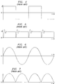
- FIGURE 4 is a plot of the current for an alternating current arc lamp.
- FIGURE 5 is a plot of the intensity of light generated by an arc lamp receiving the current waveform shown in Figure 4.
- FIGURE 6 is a plot of the current for an alternating current arc lamp.
- FIGURE 7 is a plot of the intensity of light generated by an arc lamp receiving the current waveform shown in Figure 6.
- FIGURE 8 is a block diagram of a portion of a pulse-width modulated display system showing a processor for modifying and storing bit sequences.
- FIGURE 9 is a plot of the intensity of light generated by a light source.
- FIGURE 10 is a schematic view of a micromirror-based projection system utilizing the adaptive temporal modulation techniques taught herein.
- a new method and system for controlling the intensity of a pixel in a pulse width modulated display system has been developed.
- the new method and system improve the accuracy of pulse width modulated display systems by adapting the duration of the pulses to account for variations in the output of the light source. Since the effective brightness of a pixel is a function of the light accumulated by the pixel, taking into account both the duration and the intensity of the light directed to the pixel provides a more accurate determination of the pixel intensity than duration alone.
- Figure 1 is a timeline of a simple pulse width modulation frame period.
- the frame period 102 shown in Figure 1 is divided into seven individual bit periods. During each bit period, a single data bit from a seven-bit intensity word is used to control the light modulator. The length of each bit period is proportional to the magnitude represented by the bit, or bit weight.
- bit period 104 For example, the most significant bit (MSB) in the seven-bit binary-weighted intensity word is displayed during period 104.
- Bit period 104 has a duration of 64/127 of the total frame period 102.
- the next most significant bit has a bit period 106 equal to half of the MSB bit period 104, or 32/127 of the total frame period.
- bit period 108 has a duration of 16/127 of the total frame period
- bit period 110 has a duration of 8/127 of the total frame period
- bit period 112 has a duration of 4/127 of the total frame period
- bit period 114 has a duration of 2/127 of the total frame period
- bit period 116 has a duration of 1/127 of the total frame period.
- the bit period for a bit is equal to 2 n-1 /(2 m -1) where n is the weight of the bit and m is the total number of bits in the intensity word.
- bit periods shown in Figure 1 tend to create artifacts when showing moving images. To avoid artifacts, the longer bit periods are split into two or more bit splits and distributed throughout the frame period 102. The total duration for all of the bit splits for a given image bit equal the bit period shown in Figure 1.
- Figure 2 shows a timeline for a pulse width modulated frame period where the two most significant bit periods are split. The MSB bit period has been split into four bit splits 104a, 104b, 104c, and 104d, and the next MSB bit period has been split into two bit splits 106a and 106b. The terms bit split and bit periods are often used interchangeably.
- the optimum bit sequence is determined by many factors including the data word size, the frame rate, the speed of the display device, and the time required to load the display device. Since the frame rate can vary depending on the capability of the display device to display multiple image formats and also on the ability of the image source to provide an accurate and consistent image input, several different sequences are used by each display system. These sequences are stored in a sequence read only memory (ROM) 302 shown in Figure 3. A sequencer 304 selects a particular sequence and reads the sequence from the sequence ROM 302. The sequence indicates the order and duration for each of the bit periods or bit splits in the sequence. The sequencer 304 controls the timing of the control signals that load and reset the display device 306.
- ROM read only memory
- sequencer ROM 302 and the sequencer 304 are typically two components in a much more complex application specific integrated circuit (ASIC) or gate array that processes the image data as well as controls the display device. Therefore, the statement that the sequencer ROM controls the timing of, or drives the control signals that load and reset the display device 306 comprehends the possibility that the controlling or driving is in addition to or through other parts of the circuit that may also control or drive the display device timing and control signals.
- ASIC application specific integrated circuit
- the effect of the ringing shown in Figure 5 can been eliminated by hiding the transition in a spoke period in a color wheel-based display system.
- the display device is turned off during the ringing. Unfortunately, turning "OFF" the device and extending a spoke period longer than necessary, both reduce the brightness of the display system.
- Figure 6 is the waveform for a sinusoidal arc current. While sinusoidal waveforms are not likely to be used to drive arc lamps, the sinusoidal waveform of Figure 6 provides a good illustration of the problems of time-varying light sources, and may approximate the waveform of a band-limited high frequency AC driver current.
- Figure 7 is a plot of the intensity of light emitted by an arc lamp being driven by the alternating current of Figure 6.
- bit periods shown in Figures 1 and 2 with a time-varying light source alters the relative weights of the image bits as displayed. For example, a data bit displayed during a peak of the waveform shown in Figure 7 may provide much more illumination than a more significant bit displayed during a minimal-intensity period of Figure 7.
- Prior art display systems could not compensate for the varying light intensity-except using the blanking periods described above-and therefore could not use light sources with less-stable outputs.
- a new display system controller 800 and method has been developed that will allow the use of less-stable light output.
- the new display system controller 800 is shown in Figure 8.
- the system controller 800 uses a two-port random access memory (RAM) 802 to store the bit period sequences used by the sequencer 304.
- the sequences are stored in ROM 804 and read by processor 806 which selects a sequence and stores the selected sequence in RAM 802.
- RAM random access memory
- System controller 800 also includes a detector 808 to sense the output of the light source.
- a signal representing the output intensity of the light source is driven to a processor 806 by the detector 808.
- the signal is typically an analog signal that is sampled by an analog-to-digital converter included in processor 806.
- the output of detector 808 must be sampled above the Nyquist rate to avoid aliasing.
- the intensity of the periodically-varying lamp output is integrated by the processor 806 to determine the total light available during each frame period.
- the processor uses the sampled light waveform and the calculated total light to modify each bit period in the bit sequence. For example, bit periods during above average lamp output periods are shortened, while bit periods during below average lamp output periods are lengthened.
- the duration of each bit period or bit split is equal to (2 n-1 /(2 m -1) * (I avg /I n ) * (1/i): where n is the weight of the bit, m is the total number of bits in the intensity word, I avg is the average intensity of the light during a frame period, I n is the intensity of light during a given bit split, and i is the number of bit splits a given bit is divided into.
- Arc lamps generally have a periodic waveform that varies slowly over time. If the lamp is assumed to be relatively stable from one period to the next, very little processing power is required to implement the disclosed teachings.
- Figure 9 shows a plot of the light intensity during a small portion of a frame period.
- the intensity waveform 902 is sampled at many points 904 along the waveform 902. The sampled points are accumulated over several periods to smooth the intensity waveform 902. Smoothing the waveform reduces the impact of unique excursions from the periodic waveform.
- additional intensity points 906 may be calculated from the sampled data points 904. Depending on the number of samples 904, linear interpolation between the samples 904 may be sufficient to provide an accurate representation of the waveform 902.
- bit periods can be altered to increase the accuracy of the pulse width modulation.
- a bit split, or bit period starts at time t (n) and extends to time t (n+1) .
- the intensity under curve 902 is integrated by summing each sample 904 or interpolated sample 906. If the measured illumination during the bit period, represented by area 908, is a larger portion of the total frame illumination than desired, the bit sequence is modified to end the bit period before time t (n+1) .
- Figure 9 also shows a second bit period having an illumination represented by the area 910, and an optional load period or blanking period between time t (n+1) and time t (n+2) .
- the processor 806 reads the current sequence from the two-port RAM 802. The processor then adds or subtracts to the duration of the bit periods in the sequence and stores the updated sequence in the two-port RAM 802.
- a two-port RAM is ideally, but not necessarily, used to hold the updated sequences
- the sequence update rate and the bit period display rates are not tightly coupled.
- Various embodiments of the present invention sample the lamp intensity, update the accumulated waveform data, and alter the bit period sequence at various rates.
- the sample, accumulation, and alter rates are independent and perform different functions.
- a faster sample rate provides more accurate estimates of the total periodic intensity of the lamp, and more accurate estimates of the total intensity during a given bit split.
- the faster the accumulated intensity responds to recent data that is the quicker older data decays, the less smoothing will occur and the quicker the system will respond to changes in the lamp waveform.
- the faster the bit period sequence is modified the quicker the system will respond to changes in the lamp waveform and the more non-periodic excursions by the lamp will cause bit period errors.
- the sampled periodic intensity waveform is accumulated in various ways.
- One embodiment provides a very fast processor to calculate a new bit sequence using only the samples from the current period and the total integrated intensity value from the previous period.
- another embodiment uses a slow processor, or a small amount of the available processing power, to update the bit period sequence stored in the two-port RAM by the minimum possible increment each lamp period. While either extreme will work well in the proper circumstances, it is envisioned that the samples from each new lamp period will contribute between 1% and 10% of the total accumulated waveform data.
- the sample, accumulate, and update rates need not be constant.
- the default bit period sequence is changed rapidly upon system powerup in order to allow the system to quickly adapt to the lamp characteristics. After the sequence has been modified, the rate of change is limited to add stability to the system and reduce the processing required by the intensity tracking and bit period adjustment functions.
- some lamps may exhibit unstable waveforms during a powerup and warmup period. In this case the processor is allowed to modify the bit period sequence rapidly during the powerup and warmup period. Once the lamp stabilizes the modification rate can be decreased.
- the operation of the system described above must be modified to accommodate the light variations within the frame period.
- Some display systems use light sources that are switched to provide varying colors of light.
- three primary color light sources such as lasers or light emitting diodes, may be individually enabled to sequentially provide primary color light.
- the processor can use the techniques taught herein to alter each color period to equalize the actual amount of light provided by the light source, or light sources, during each of the three primary color periods.
- the duration of the individual primary color light periods cannot be altered, however, as is the case when a spinning color wheel or drum is used to filter a white light source, variations in the output of the lamp are likely to cause unequal amounts of light during each primary color period.
- the processor can respond to unequal amounts of primary colored light.
- the processor may simply ignore the fact that the primaries are unbalanced and use the techniques taught herein solely to balance the relative bit-weights within each primary color.
- the processor uses the light available during one primary color period as a reference when dividing all three primary color periods into bit periods. If the primary color period having a minimum total intensity is used as the reference, image brightness will be decreased, while color accuracy will be improved. Image brightness is decreased because the additional light available during the two brightest primary color periods will not be used. Color accuracy will increase because the image light provided by each image bit will accurately represent the weight of the image bit not only within each primary color, but also between primary colors.
- FIG 10 is a schematic view of one embodiment of an image projection system 1000 implementing the adaptive temporal modulation of a periodically varying light source methods taught herein.
- light from light source 1002 is reflected by a cold mirror 1004 and focused on a micromirror device 1006 by lens 1008.
- lens 1008 is typically a group of lenses and mirrors which together focus and direct light from the light source 1002 through a prism assembly 1010 and onto the surface of the micromirror device 1006.
- Image data and control signals from controller 1012 cause some mirrors to rotate to an on position and others to rotate to an off position.
- Mirrors on the micromirror device that are rotated to an off position reflect light to a light trap 1014 while mirrors rotated to an on position reflect light to projection lens 1016.
- Projection lens 1016 focuses the light modulated by the micromirror device 1006 onto an image plane or screen 1018.
- FIG 10 Also shown in Figure 10 are many light detectors for providing an indication of the intensity of the light source to the controller as shown in Figure 8. Although many light detectors are shown in Figure 10, generally only one detector is necessary or desired. The type and location of the detector depends on the individual system design. For example, a photodetector or other light detector 1020 is placed in the illumination path of the projector and intercepts a portion of the light headed to the light modulator 1006. Alternatively, light detector 1022 is used to detect the light reflected by one of the transmissive elements in the optical path. The advantage of using light detector 1022 is that the light it captures is from a ghost reflection and therefore does not reduce the light available to the light modulator 1006. Many other alternative light detector locations are available. For example, light detector 1024 monitors light passing through the illumination prism assembly 1010. Light detector 1026 measures the light entering the light trap 1014. Light detector 1026 measures the light scattered in the projector housing. Light detector 1030 measures the light reflected by the image screen 1018.
- the signal from the light detector may not directly represent the amount of light output by the lamp source 1002.
- the light reaching a detector 1026 in the light trap 1014 is primarily a function of the image data provided to the modulator 1006, not merely the output of the light source 1002.
- a processor could determine the periodic output of the light source 1002 by measuring the light outside the illumination path and accounting for the influence of image data on the collected light.
- the system controller 1012 can simply monitor the current output of the lamp power supply 1032.
- a second proxy for the visible light reaching the modulator 1006 is the infrared light passing through the cold mirror 1004. While not all systems use cold mirrors, those that do use cold mirrors can position an infrared detector 1034 behind the cold mirror to measure the infrared light passing through the cold mirror 1004. As long as the amount of infrared light provided by the light source 1002 track the amount of visible light, the output of the infrared detector is a good proxy for the visible light output.
Landscapes
- Engineering & Computer Science (AREA)
- Physics & Mathematics (AREA)
- Computer Hardware Design (AREA)
- General Physics & Mathematics (AREA)
- Theoretical Computer Science (AREA)
- Multimedia (AREA)
- Signal Processing (AREA)
- Control Of Indicators Other Than Cathode Ray Tubes (AREA)
- Mechanical Light Control Or Optical Switches (AREA)
- Optical Modulation, Optical Deflection, Nonlinear Optics, Optical Demodulation, Optical Logic Elements (AREA)
- Projection Apparatus (AREA)
Applications Claiming Priority (2)
| Application Number | Priority Date | Filing Date | Title |
|---|---|---|---|
| US11404498P | 1998-12-28 | 1998-12-28 | |
| US114044 | 1998-12-28 |
Publications (3)
| Publication Number | Publication Date |
|---|---|
| EP1018723A2 true EP1018723A2 (fr) | 2000-07-12 |
| EP1018723A3 EP1018723A3 (fr) | 2002-03-20 |
| EP1018723B1 EP1018723B1 (fr) | 2005-11-16 |
Family
ID=22353069
Family Applications (1)
| Application Number | Title | Priority Date | Filing Date |
|---|---|---|---|
| EP99204582A Expired - Lifetime EP1018723B1 (fr) | 1998-12-28 | 1999-12-24 | Commande d'échelle de gris d'un système d'affichage |
Country Status (4)
| Country | Link |
|---|---|
| US (1) | US6285491B1 (fr) |
| EP (1) | EP1018723B1 (fr) |
| JP (1) | JP2000193914A (fr) |
| DE (1) | DE69928365T2 (fr) |
Cited By (6)
| Publication number | Priority date | Publication date | Assignee | Title |
|---|---|---|---|---|
| WO2005111977A1 (fr) * | 2004-05-10 | 2005-11-24 | Infocus Corporation | Appareil de projection comprenant un systeme de commande de diodes electroluminescentes a retroaction et procede d'activation associe |
| WO2006114742A3 (fr) * | 2005-04-28 | 2007-04-05 | Philips Intellectual Property | Systeme de projection et procede de mise en oeuvre d'un systeme de projection |
| WO2007108522A1 (fr) * | 2006-03-17 | 2007-09-27 | Casio Computer Co., Ltd. | appareil de projection, méthodes de projection et programme informatique |
| CN104424874A (zh) * | 2013-08-19 | 2015-03-18 | 珠海格力电器股份有限公司 | 家用电器控制装置、家用电器及其显示控制方法 |
| EP2437104A4 (fr) * | 2009-05-29 | 2016-03-02 | Nippon Seiki Co Ltd | Dispositif d'affichage à cristaux liquides |
| CN110297323A (zh) * | 2018-03-22 | 2019-10-01 | 三美电机株式会社 | 促动器以及光扫描装置 |
Families Citing this family (8)
| Publication number | Priority date | Publication date | Assignee | Title |
|---|---|---|---|---|
| EP1532481A4 (fr) * | 2002-05-06 | 2009-04-22 | Uni Pixel Displays Inc | Efficacite de couleur a sequences de trames |
| US7359026B2 (en) * | 2002-05-13 | 2008-04-15 | Paul Bullwinkel | Liquid crystal display projector |
| US7410262B2 (en) * | 2005-08-02 | 2008-08-12 | Tte Technology, Inc. | System and method for compensating for spoke light |
| US9160914B2 (en) * | 2011-06-28 | 2015-10-13 | Inview Technology Corporation | User control of the visual performance of a compressive imaging system |
| JP2013182142A (ja) * | 2012-03-02 | 2013-09-12 | Mitsubishi Electric Corp | マルチ画面表示装置 |
| US10237523B2 (en) | 2013-05-07 | 2019-03-19 | Dolby Laboratories Licensing Corporation | Digital point spread function (DPSF) and dual modulation projection (including lasers) using DPSF |
| EP4723086A1 (fr) | 2013-05-07 | 2026-04-08 | Dolby Laboratories Licensing Corporation | Imagerie à demi-teintes multiples et projection à double modulation/projection laser à double modulation |
| CN113744354B (zh) * | 2021-11-05 | 2022-02-22 | 苏州浪潮智能科技有限公司 | 一种基于灰度值调节亮度的方法、装置、设备及可读介质 |
Family Cites Families (11)
| Publication number | Priority date | Publication date | Assignee | Title |
|---|---|---|---|---|
| US4197559A (en) * | 1978-10-12 | 1980-04-08 | Gramling Wiliam D | Color television display system |
| GB2251511A (en) * | 1991-01-04 | 1992-07-08 | Rank Brimar Ltd | Display device. |
| CA2063744C (fr) | 1991-04-01 | 2002-10-08 | Paul M. Urbanus | Architecture et dispositif de synchronisation de systeme d'affichage a modulation d'impulsions en duree |
| GB9223114D0 (en) * | 1992-11-04 | 1992-12-16 | Rank Brimar Ltd | Display system |
| US5365283A (en) * | 1993-07-19 | 1994-11-15 | Texas Instruments Incorporated | Color phase control for projection display using spatial light modulator |
| US6362835B1 (en) * | 1993-11-23 | 2002-03-26 | Texas Instruments Incorporated | Brightness and contrast control for a digital pulse-width modulated display system |
| US5583688A (en) | 1993-12-21 | 1996-12-10 | Texas Instruments Incorporated | Multi-level digital micromirror device |
| US5706061A (en) * | 1995-03-31 | 1998-01-06 | Texas Instruments Incorporated | Spatial light image display system with synchronized and modulated light source |
| US5986721A (en) * | 1995-06-13 | 1999-11-16 | Texas Instruments Incorporated | Producing a rendered image version of an original image using an image structure map representation of the image |
| CA2184129A1 (fr) * | 1995-08-31 | 1997-03-01 | Donald B. Doherty | Segmentation de bits pour modulateur de lumiere spatial module en duree par des impulsions |
| US6201521B1 (en) * | 1995-09-29 | 2001-03-13 | Texas Instruments Incorporated | Divided reset for addressing spatial light modulator |
-
1999
- 1999-12-21 US US09/467,816 patent/US6285491B1/en not_active Expired - Lifetime
- 1999-12-24 DE DE69928365T patent/DE69928365T2/de not_active Expired - Lifetime
- 1999-12-24 EP EP99204582A patent/EP1018723B1/fr not_active Expired - Lifetime
- 1999-12-24 JP JP11368115A patent/JP2000193914A/ja not_active Abandoned
Cited By (11)
| Publication number | Priority date | Publication date | Assignee | Title |
|---|---|---|---|---|
| WO2005111977A1 (fr) * | 2004-05-10 | 2005-11-24 | Infocus Corporation | Appareil de projection comprenant un systeme de commande de diodes electroluminescentes a retroaction et procede d'activation associe |
| US7172295B2 (en) | 2004-05-10 | 2007-02-06 | Infocus Corporation | LED control system with feedback |
| WO2006114742A3 (fr) * | 2005-04-28 | 2007-04-05 | Philips Intellectual Property | Systeme de projection et procede de mise en oeuvre d'un systeme de projection |
| US7887196B2 (en) | 2005-04-28 | 2011-02-15 | Koninklijke Philips Electronics N.V. | Projection system and method for operating a projection system to compensate for overshoot sequence |
| CN101167370B (zh) * | 2005-04-28 | 2011-09-07 | 皇家飞利浦电子股份有限公司 | 投影系统及用于操作投影系统的方法 |
| WO2007108522A1 (fr) * | 2006-03-17 | 2007-09-27 | Casio Computer Co., Ltd. | appareil de projection, méthodes de projection et programme informatique |
| US7976172B2 (en) * | 2006-03-17 | 2011-07-12 | Casio Computer Co., Ltd. | Projection apparatus, projection method, and computer program |
| EP2437104A4 (fr) * | 2009-05-29 | 2016-03-02 | Nippon Seiki Co Ltd | Dispositif d'affichage à cristaux liquides |
| CN104424874A (zh) * | 2013-08-19 | 2015-03-18 | 珠海格力电器股份有限公司 | 家用电器控制装置、家用电器及其显示控制方法 |
| CN110297323A (zh) * | 2018-03-22 | 2019-10-01 | 三美电机株式会社 | 促动器以及光扫描装置 |
| CN110297323B (zh) * | 2018-03-22 | 2022-07-01 | 三美电机株式会社 | 促动器以及光扫描装置 |
Also Published As
| Publication number | Publication date |
|---|---|
| JP2000193914A (ja) | 2000-07-14 |
| DE69928365T2 (de) | 2006-07-13 |
| DE69928365D1 (de) | 2005-12-22 |
| EP1018723B1 (fr) | 2005-11-16 |
| EP1018723A3 (fr) | 2002-03-20 |
| US6285491B1 (en) | 2001-09-04 |
Similar Documents
| Publication | Publication Date | Title |
|---|---|---|
| US6285491B1 (en) | Adaptive temporal modulation of periodically varying light sources | |
| US5986640A (en) | Display device using time division modulation to display grey scale | |
| KR101466119B1 (ko) | 디스플레이장치 및 그 광조절방법 | |
| US7661828B2 (en) | Adjusting light intensity | |
| KR20030076441A (ko) | 디지털 미러장치 프로젝터 및 디지털 미러장치 프로젝터에사용되는 비디오 신호의 보정 방법 | |
| US7954960B2 (en) | Video image display apparatus and timing control method | |
| US8061846B2 (en) | Light source control method for video image display apparatus and video image display apparatus | |
| US20070013871A1 (en) | Light-emitting diode (LED) illumination in display systems using spatial light modulators (SLM) | |
| US20080218458A1 (en) | Color display system | |
| US20060192899A1 (en) | Projection type video reproducing apparatus | |
| US20090147033A1 (en) | Color display system | |
| WO2008027231A2 (fr) | Système d'affichage comprenant un dispositif à miroirs présentant un état d'oscillation | |
| US7969640B2 (en) | Color display system | |
| US20090174810A1 (en) | Video display system | |
| JPWO2008066040A1 (ja) | 映像表示装置、映像表示方法、プログラム、及び記録媒体 | |
| GB2400768A (en) | Scanner with movable calibration target | |
| WO1995027970A1 (fr) | Dispositif d'affichage | |
| CN101371289B (zh) | 使用脉冲灯在视频显示系统中增加位深度的系统和方法 | |
| JPWO2001057836A1 (ja) | 画像表示方法、画像表示装置及びそれに用いる制御回路 | |
| CN114901121B (zh) | 具有同步的光源和相机的眼科显微镜 | |
| US20090141194A1 (en) | Apparatus and method, both for controlling spatial light modulator | |
| EP1564711B1 (fr) | Dispositif de transmission de lumière | |
| JPH1178117A (ja) | 画像形成装置及び画像形成方法 | |
| JPH1169264A (ja) | 液晶プロジェクタ | |
| US8350790B2 (en) | Video display system |
Legal Events
| Date | Code | Title | Description |
|---|---|---|---|
| PUAI | Public reference made under article 153(3) epc to a published international application that has entered the european phase |
Free format text: ORIGINAL CODE: 0009012 |
|
| AK | Designated contracting states |
Kind code of ref document: A2 Designated state(s): AT BE CH CY DE DK ES FI FR GB GR IE IT LI LU MC NL PT SE |
|
| AX | Request for extension of the european patent |
Free format text: AL;LT;LV;MK;RO;SI |
|
| PUAL | Search report despatched |
Free format text: ORIGINAL CODE: 0009013 |
|
| AK | Designated contracting states |
Kind code of ref document: A3 Designated state(s): AT BE CH CY DE DK ES FI FR GB GR IE IT LI LU MC NL PT SE |
|
| AX | Request for extension of the european patent |
Free format text: AL;LT;LV;MK;RO;SI |
|
| 17P | Request for examination filed |
Effective date: 20020920 |
|
| AKX | Designation fees paid |
Free format text: AT BE CH CY DE DK ES FI FR GB GR IE IT LI LU MC NL PT SE |
|
| RBV | Designated contracting states (corrected) |
Designated state(s): DE FR GB |
|
| 17Q | First examination report despatched |
Effective date: 20021127 |
|
| GRAP | Despatch of communication of intention to grant a patent |
Free format text: ORIGINAL CODE: EPIDOSNIGR1 |
|
| GRAS | Grant fee paid |
Free format text: ORIGINAL CODE: EPIDOSNIGR3 |
|
| GRAA | (expected) grant |
Free format text: ORIGINAL CODE: 0009210 |
|
| AK | Designated contracting states |
Kind code of ref document: B1 Designated state(s): DE FR GB |
|
| REG | Reference to a national code |
Ref country code: GB Ref legal event code: FG4D |
|
| REF | Corresponds to: |
Ref document number: 69928365 Country of ref document: DE Date of ref document: 20051222 Kind code of ref document: P |
|
| ET | Fr: translation filed | ||
| PLBE | No opposition filed within time limit |
Free format text: ORIGINAL CODE: 0009261 |
|
| STAA | Information on the status of an ep patent application or granted ep patent |
Free format text: STATUS: NO OPPOSITION FILED WITHIN TIME LIMIT |
|
| 26N | No opposition filed |
Effective date: 20060817 |
|
| PGFP | Annual fee paid to national office [announced via postgrant information from national office to epo] |
Ref country code: GB Payment date: 20141124 Year of fee payment: 16 |
|
| PGFP | Annual fee paid to national office [announced via postgrant information from national office to epo] |
Ref country code: FR Payment date: 20141124 Year of fee payment: 16 |
|
| PGFP | Annual fee paid to national office [announced via postgrant information from national office to epo] |
Ref country code: DE Payment date: 20141222 Year of fee payment: 16 |
|
| REG | Reference to a national code |
Ref country code: DE Ref legal event code: R119 Ref document number: 69928365 Country of ref document: DE |
|
| GBPC | Gb: european patent ceased through non-payment of renewal fee |
Effective date: 20151224 |
|
| REG | Reference to a national code |
Ref country code: FR Ref legal event code: ST Effective date: 20160831 |
|
| PG25 | Lapsed in a contracting state [announced via postgrant information from national office to epo] |
Ref country code: DE Free format text: LAPSE BECAUSE OF NON-PAYMENT OF DUE FEES Effective date: 20160701 Ref country code: GB Free format text: LAPSE BECAUSE OF NON-PAYMENT OF DUE FEES Effective date: 20151224 |
|
| PG25 | Lapsed in a contracting state [announced via postgrant information from national office to epo] |
Ref country code: FR Free format text: LAPSE BECAUSE OF NON-PAYMENT OF DUE FEES Effective date: 20151231 |