EP1018741A1 - Kontrolle zur Unterbrechung der Datenaufzeichnung auf einer Platte - Google Patents
Kontrolle zur Unterbrechung der Datenaufzeichnung auf einer Platte Download PDFInfo
- Publication number
- EP1018741A1 EP1018741A1 EP99310539A EP99310539A EP1018741A1 EP 1018741 A1 EP1018741 A1 EP 1018741A1 EP 99310539 A EP99310539 A EP 99310539A EP 99310539 A EP99310539 A EP 99310539A EP 1018741 A1 EP1018741 A1 EP 1018741A1
- Authority
- EP
- European Patent Office
- Prior art keywords
- data
- disk
- recording
- data processing
- writing
- Prior art date
- Legal status (The legal status is an assumption and is not a legal conclusion. Google has not performed a legal analysis and makes no representation as to the accuracy of the status listed.)
- Granted
Links
Images

Classifications
-
- G—PHYSICS
- G11—INFORMATION STORAGE
- G11B—INFORMATION STORAGE BASED ON RELATIVE MOVEMENT BETWEEN RECORD CARRIER AND TRANSDUCER
- G11B20/00—Signal processing not specific to the method of recording or reproducing; Circuits therefor
- G11B20/10—Digital recording or reproducing
- G11B20/10527—Audio or video recording; Data buffering arrangements
-
- G—PHYSICS
- G11—INFORMATION STORAGE
- G11B—INFORMATION STORAGE BASED ON RELATIVE MOVEMENT BETWEEN RECORD CARRIER AND TRANSDUCER
- G11B19/00—Driving, starting, stopping record carriers not specifically of filamentary or web form, or of supports therefor; Control thereof; Control of operating function ; Driving both disc and head
- G11B19/20—Driving; Starting; Stopping; Control thereof
- G11B19/28—Speed controlling, regulating, or indicating
-
- G—PHYSICS
- G11—INFORMATION STORAGE
- G11B—INFORMATION STORAGE BASED ON RELATIVE MOVEMENT BETWEEN RECORD CARRIER AND TRANSDUCER
- G11B27/00—Editing; Indexing; Addressing; Timing or synchronising; Monitoring; Measuring tape travel
- G11B27/02—Editing, e.g. varying the order of information signals recorded on, or reproduced from, record carriers
- G11B27/031—Electronic editing of digitised analogue information signals, e.g. audio or video signals
- G11B27/034—Electronic editing of digitised analogue information signals, e.g. audio or video signals on discs
-
- G—PHYSICS
- G11—INFORMATION STORAGE
- G11B—INFORMATION STORAGE BASED ON RELATIVE MOVEMENT BETWEEN RECORD CARRIER AND TRANSDUCER
- G11B20/00—Signal processing not specific to the method of recording or reproducing; Circuits therefor
- G11B20/10—Digital recording or reproducing
- G11B20/10527—Audio or video recording; Data buffering arrangements
- G11B2020/1062—Data buffering arrangements, e.g. recording or playback buffers
- G11B2020/10814—Data buffering arrangements, e.g. recording or playback buffers involving specific measures to prevent a buffer underrun
-
- G—PHYSICS
- G11—INFORMATION STORAGE
- G11B—INFORMATION STORAGE BASED ON RELATIVE MOVEMENT BETWEEN RECORD CARRIER AND TRANSDUCER
- G11B2220/00—Record carriers by type
- G11B2220/20—Disc-shaped record carriers
- G11B2220/21—Disc-shaped record carriers characterised in that the disc is of read-only, rewritable, or recordable type
- G11B2220/215—Recordable discs
- G11B2220/218—Write-once discs
-
- G—PHYSICS
- G11—INFORMATION STORAGE
- G11B—INFORMATION STORAGE BASED ON RELATIVE MOVEMENT BETWEEN RECORD CARRIER AND TRANSDUCER
- G11B2220/00—Record carriers by type
- G11B2220/20—Disc-shaped record carriers
- G11B2220/25—Disc-shaped record carriers characterised in that the disc is based on a specific recording technology
- G11B2220/2537—Optical discs
- G11B2220/2545—CDs
-
- G—PHYSICS
- G11—INFORMATION STORAGE
- G11B—INFORMATION STORAGE BASED ON RELATIVE MOVEMENT BETWEEN RECORD CARRIER AND TRANSDUCER
- G11B7/00—Recording or reproducing by optical means, e.g. recording using a thermal beam of optical radiation by modifying optical properties or the physical structure, reproducing using an optical beam at lower power by sensing optical properties; Record carriers therefor
- G11B7/004—Recording, reproducing or erasing methods; Read, write or erase circuits therefor
- G11B7/0045—Recording
Definitions
- the present invention relates to a disk recording device capable of additional data writing while preserving data continuity, and in particular to a disk recording device capable of power saving when recording data onto the disk, the data being supplied at a slower transfer speed than a data writing speed.
- a CD-R (compact disk recordable) drive a type of CD drive, is known as a disk recording device for recording data on a CD-R disk.
- a CD-R disk To record audio data to a CD-R disk, using as source audio data recorded in a CD-DA (CD-Digital Audio), using a CD-R drive, it is necessary to apply a disk-at-once method in view of compatibility with a CD-DA player.
- Write-once media such as a CD-R, which are incapable of physical erasure of once recorded data, have a problem such that, should recording data be discontinued, medium regions (e.g., a track) used in the recording can not be used again.
- a disk reproducing device on a sender side sends audio or video data at a standard defined rate to the disk, and the sent data is received by a disk recording device and used in data writing onto a disk.
- a data processing rate at which the disk recording device writes data onto a disk is faster than a data transfer rata at which the sender sends recording data.
- data recording onto a disk is suspended until an amount of data equivalent to the data writing capacity has been stored in a buffer memory.
- data recording onto a disk is suspended during a period when the data recording capacity of the disk recording device exceeds a data transfer speed, achieving a reduction of power consumption.
- data to follow the recorded data on the disk can be additionally written onto the disk without a break in the data.
- a data sender can control data transmission in accordance with the state of data writing onto a disk, by setting a full data writing capacity of a buffer memory at a full memory capacity thereof, a period of suspended data recording onto a disk can be set so as to make best use of the memory capacity of the buffer memory, in addition to achievement of power consumption reduction.
- the suspended data recording period can accordingly be prolonged, achieving further reduction of power consumption.
- Fig. 1 is a block diagram showing a circuit of a preferred embodiment of a disk recording device according to the present invention in the form of a CD-R drive.
- the drawing shows an optical head 1 for irradiating a laser beam for tracing a disk to perform writing or reading of recording data with respect to a disk, an RF amplifier 2 for amplifying an RF signal (a high frequency signal) obtained by reading recorded data from the disk by the optical head 1, and for binarizing the RF signal into digital data to output, and a head servo circuit 3 for feed-backing an output from the optical head 1 received via the RF amplifier 2 to achieve focusing control, tracking control, and thread feeding control.
- the focusing control the laser beam is focused on a signal plane of the disk.
- the tracking control the laser beam tracks the signal track of the disk.
- the optical head 1 is moved in the radial direction of the disk.
- a decoder 4 is responsible for signal processing to demodulate digital data output from the RF amplifier 2.
- a sub-code demodulation circuit 5 demodulates a sub-code separated from the data.
- the decoder 4 demodulates the data read from the disk in synchronism with a bit clock reproduced from the read data.
- the demodulation is achieved free from the influence of variation of a disk rotation speed.
- a wobble decoder 6 extracts 22.05 kHz wobble components from a pre-groove signal obtained via the RF amplifier 2 to generate components necessary for disk rotation control.
- the wobble decoder 6 includes an ATIP demodulation circuit 7 for demodulating wobble components to restore an ATIP (absolute time in pre-groove).
- a disk motor 8 drives a disk for rotation.
- a motor servo circuit 9 performs driving control for the disk motor 8.
- the motor servo 9 is capable of rotation control of a disk with signals recorded using a constant linear velocity method, as well as rotation control of a disk using a constant angular velocity method when reproducing data from the disk.
- An interface 10 is connected, via a connection terminal 11, with the outside for controlling data transmission with an external device.
- An encoder 12 modulates data received via the interface 10 into recording data to be recorded onto a disk.
- a buffer RAM 13 is used for caching data from an external device connected to the connection terminal 11 and used as a memory when the cached data is modulated in the encoder 12 into recording data to be recorded onto a disk. Furthermore, the buffer RAM 13 is used for caching data read from the disk, and used as a memory when the data is demodulated in the decoder 4.
- the encoder 12 has a CD-ROM modulator for modulation based on CD-ROM standard, and a CD modulator for modulation based on CD-DA standard.
- the CD-ROM modulator imparts synchronization (sync), header, EDC (error detection code), and ECC (error correction code) to receiving data, EDC being an error detection code for CD-ROM data, and ECC being an error correction code for CD-ROM data.
- the CD modulator performs CIRC (cross interleaved reed-solomon code) processing and imparts a sub-code to data output from the CD-ROM modulator, CIRC being an error correction code in a CD method.
- the CD modulator also performs EFM (eight to fourteen modulation) and imparts a synchronous signal.
- a laser driver circuit 14 drives a laser source of the optical head 1 to record data onto a disk based on recording data in the form of EFM data output from the encoder 12.
- a system control circuit 15 is responsible for system control in connection with data recording onto and reproduction from a disk.
- the system control circuit 15 comprises an access control means 16, a buffer control means 17, a recording control means 18, a recording start position detection means 19, a synchronism setting means 20, and an operation suspension control means 21.
- the access control means 16 controls accesses with selective reference to a sub-code address shown in absolute time information contained in a sub-code (sub-Q-code), which was demodulated in the sub-code demodulation circuit 5, and an ATIP address shown in absolute time information contained in_an ATIP, which was demodulated in the ATIP demodulation circuit 7.
- the buffer control means controls data writing and reading with respect to the buffer RAM 13.
- the reading control means 18 controls data reading from or recording onto a disk depending on the amount of data having been stored in the butter RAM 13 through control by the buffer control means 17.
- the recording start position detection means 19 detects the beginning of a region with no recorded data on the disk to thereby detect a recording start position, at which the recording control means 18 starts data recording.
- the synchronism setting means 20 synchronizes recording data to be newly recorded on a disk with recorded data onto the disk, using a synchronous signal of a sub-code extracted by the decoder 4 and sub-Q-data demodulated by the sub-code demodulation circuit 5.
- the operation suspension control means 21 controls operation suspension by halting power supply to a predetermined circuit depending on the amount of data stored in the buffer RAM 13 through control by the buffer control circuit 17.
- the operation suspension control circuit 21 controls operation suspension of the circuits shown enclosed by the broken line in Fig. 1, namely reproduction circuits for processes from data reading from a disk to data demodulation, and recording circuits for processes from modulation of received data into recording data to be recorded onto a disk to data writing onto a disk, by halting power supply to these circuits.
- the thus constructed disk recording device executes a recording operation upon receipt, via the interface 10, of data to be recorded onto a disk.
- a reference clock with crystal oscillation accuracy is then used as a system clock for recording circuits.
- the optical head 1 is controlled so as to read a pre-groove signal from a disk, using a laser output for disk reproduction.
- the pre-groove signal read by the optical head 1 is supplied to the RF amplifier 2 for waveform shaping before wobble components are extracted therefrom in the wobble decoder 6.
- the extracted wobble components are demodulated into an ATIP in the ATIP demodulation circuit 7.
- the data When data to record is supplied from an external device connected to the connection terminal 11, the data is received by the interface 10 and then written into the buffer RAM 13.
- the data written in the buffer RAM 13 is modulated in the encoder 12 into recording data in a suitable form for recording onto a disk.
- the encoder 12 sequentially outputs recording data using the EFM frame unit, while address data indicative of an address corresponding to the output recording data is sequentially updated and stored in the address memory 15a in the system control circuit 15.
- the laser driving circuit 14 drives the laser source of the optical head 1, based on the recording data output from the encoder 12, so that recording data is recorded onto the disk.
- the recording control means 18 determines discontinuation of data recording onto the disk. Accordingly, the encoder 12 discontinues output of recording data and the optical head 1 stops irradiation of the writing beam to thereby discontinue data writing onto the disk.
- address data corresponding to the address of the last frame of the recording data output from the encoder 12 immediately before the discontinuation is stored in the address memory 15a in the system control circuit 15.
- the stored address data includes time information concerning sub-code Q-channel data (sub-Q-data), and address information indicating that a particular frame is the n th one of the EFM frames in the time information.
- the synchronism setting means 20 knows, based on the address data stored in the address memory 15a, what exact time (hours and minutes) the time information in the sub-Q-data for the last frame of the recording data recorded immediately before the discontinuation indicates as an address of that frame, and that the last frame is the n th one of the EFM frames in the time information.
- the access control means 16 attempts to access the recording data which has been recorded on the disk by the time of discontinuation of data recording, based on an ATIP restored in the ATIP demodulation circuit 7, and the optical head 1 then begins tracing.
- a pit signal having been recorded on a disk, is read from the disk, and the RF amplifier 2 obtains EFM data, based on the pit signal.
- a system clock is switched to a reproduction clock, which is in synchronism with EFM data, so that demodulation by the decoder 4 and modulation by the encoder 12 are both carried out in synchronism with a reproduction clock.
- the encoder 12 resumes modulation to resume preparation of recording data.
- the decoder 4 extracts a synchronous signal of a sub-code, and the sub-code demodulation circuit 5 demodulates sub-Q-data. Then, using the synchronous signal and the sub-Q-data, the synchronism setting means 20 synchronizes recording data output from the encoder 12 with data recorded on the disk.
- the encoder 12 During a period until the synchronism is established, the encoder 12 remains in a waiting state, outputting recording data in a frame immediately following the last recorded frame on the disk immediately before discontinuation of the data recording by the recording control means 18.
- the encoder 12 comprises an internal RAM for use in modulation.
- the internal RAM stores data necessary for CIRC processing when data recording is discontinued, in order to ensure sufficient CIFC inter-leave length (108 EFM frames at the longest) necessary for newly supplied data.
- the recording start position detection means 19 detects the beginning of a region with no recorded data on the disk, immediately following the region with recorded data, referring to the address data stored in the address memory 15a.
- the detection of the beginning of a region with no recorded data on the disk is carried out based on the time information in sub-Q-data and information indicating that particular frame is the n th one of the EFM frames in the time information. That is, detection by the unit of a sub-code frame (a collection of 98 units of EFM frames) is made based on sub-Q-data, and further detection by the unit of an EFM frame is made by counting channel bits, using a synchronous signal as a reference. With the above detection, the end of the last frame of the recorded data on the disk is determined.
- a sub-code frame a collection of 98 units of EFM frames
- a system clock is gradually switched from a reproduction clock to a reference clock.
- the recording control means 18 controls such that the encoder 12 outputs recording data, to resume data recording.
- the synchronism setting means 20 has established synchronism between data recorded on the disk and recording data output from the encoder 12. Also, the encoder 12 outputs recording data in a frame immediately following the last recorded frame on the disk immediately before the discontinuation of data recording.
- new recording data is recorded in a region successive, without a break, to the region where the last recording date were recorded on the disk immediately before the discontinuation of data recording.
- the disk recording device shown in Fig. 1 has a high speed writing capability, such as eight times as fast as the normal speed defined as CD standard, and that data to be received by the interface 10 via the connection terminal 11 is continuous data, such as audio data, video data, or the like, and transferred at a normal speed defined as CD standard.
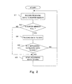
- the recording control means 18 sets either a recording suspended state, in which data recording onto a disk is suspended, or a recording state, in which data recording onto a disk is applied, depending on the amount of data stored in the buffer RAM 13. With this arrangement, data recording onto a disk is suspended while the recording capability of the disk recording device exceeds a data transferring speed.
- the recording control means 18 sets a recording suspended state to suspend data writing onto a disk, and the buffer control means 17 accordingly suspends data reading from the buffer RAM 13 (S3).
- the operation process returns to S2 to perform only data writing into the buffer RAM 13.
- the full data writing capacity of the buffer RAM 13 corresponds to the full memory capacity of the buffer RAM 13 as overflow of the buffer RAM 13 can be prevented by halting data transmission from the sender.
- the full data writing capacity of the buffer RAM 13 in this case means the full memory capacity of the buffer RAM 13 deducted by an amount of data expected to be written into the buffer RAM 13 while the buffer RAM 13 is preparing for resuming data writing onto a disk.
- the recording control means 18 releases the recording suspended state to set a recording state.
- the operation suspension control means 21 resumes power supply to the circuits shown enclosed by the broken line in Fig. 1, so that data modulation by the encoder 12, data writing onto a disk, data reading from the disk, and reproduction of read data from the disk, are resumed.
- data in the buffer RAM 13 is modulated in the encoder 12 into recording data, which is then recorded via the optical head 1 onto the disk (S4).
- data recording onto the disk is resumed beginning with a region on the disk, which is successive, without a break, to a region where recording data was last recorded immediately before the discontinuation of data recording, wherein the data to be recorded onto the disk is the data in a frame successive to the data frame last recorded on the disk immediately before the discontinuation.
- the motor servo circuit 9 controls the disk motor 8 so as to maintain the rotation speed immediately before entering the recording suspended state.
- the head servo motor 3 stores a DC voltage level of a focus control signal at the time immediately before switching to an operation suspended state, and outputs the stored DC voltage level as a focus control output when the operation suspended state is lifted.
- the optical beam from the optical head 1 comes into focus in an average state at the time when focus control was applied immediately before switching to an operation suspended state. This enables instant switching to a focus servo state.
- a period of time after releasing of a recording suspended state to beginning of disk reading for detection of a recording start position on the disk can be reduced. Accordingly, a period of time before resuming of disk recording can thus be reduced.
- a period of time till resuming of disk recording can be reduced, a period of time in a recording suspended state can be prolonged.
- the condition for releasing a recording suspended state is that an amount of data equivalent to data writing capacity has been stored in the buffer RAM 13. Therefore, when a period of time from releasing of a recording suspended state to resuming of disk recording can be reduced, timing for releasing a recording suspended state can be delayed. This enables storage of as much data as possible, within a range preventing overflowing of the buffer RAM 13, in the buffer RAM 13 so that the memory capacity of the buffer RAM 13 can be efficiently used.
- operation of the respective circuits shown enclosed by the broken line in Fig. 1 may be suspended by halting supply of an operation clock, differing from the above wherein power supply to these circuits is halted by the operation suspension control means 21, to thereby achieve reduction of power consumption.
- power consumption can be reduced corresponding to various recording methods, such as a disk-at-once method, a track-at-once method, a session-at-once method, or other packet-write methods.
- system control circuit may be constructed as a micro-computer, and in this case each means of the system control circuit is accomplished by executing a corresponding program.
- one or more means in the system control circuit can be structured as a hardware circuit.
Landscapes
- Engineering & Computer Science (AREA)
- Multimedia (AREA)
- Signal Processing (AREA)
- Signal Processing For Digital Recording And Reproducing (AREA)
- Optical Recording Or Reproduction (AREA)
Applications Claiming Priority (2)
| Application Number | Priority Date | Filing Date | Title |
|---|---|---|---|
| JP91799 | 1999-01-06 | ||
| JP11000917A JP2000200461A (ja) | 1999-01-06 | 1999-01-06 | ディスク記録装置 |
Publications (2)
| Publication Number | Publication Date |
|---|---|
| EP1018741A1 true EP1018741A1 (de) | 2000-07-12 |
| EP1018741B1 EP1018741B1 (de) | 2005-10-19 |
Family
ID=11487047
Family Applications (1)
| Application Number | Title | Priority Date | Filing Date |
|---|---|---|---|
| EP99310539A Expired - Lifetime EP1018741B1 (de) | 1999-01-06 | 1999-12-23 | Kontrolle zur Unterbrechung der Datenaufzeichnung auf einer Platte |
Country Status (6)
| Country | Link |
|---|---|
| US (1) | US6958961B2 (de) |
| EP (1) | EP1018741B1 (de) |
| JP (1) | JP2000200461A (de) |
| KR (1) | KR100684242B1 (de) |
| CN (1) | CN1171224C (de) |
| DE (1) | DE69927779T2 (de) |
Cited By (6)
| Publication number | Priority date | Publication date | Assignee | Title |
|---|---|---|---|---|
| WO2004017320A1 (en) * | 2002-08-14 | 2004-02-26 | Koninklijke Philips Electronics N.V. | Electronic device for processing data in a burst-wise manner. |
| WO2005045832A1 (en) * | 2003-11-05 | 2005-05-19 | You Jip Won | A low power data storage system and a method thereof |
| WO2007148302A3 (en) * | 2006-06-23 | 2008-03-27 | Koninkl Philips Electronics Nv | Optical drive with adaptable recording speed |
| EP1427203A4 (de) * | 2001-09-13 | 2009-12-23 | Sony Corp | Informationsaufzeichnungs-/ wiedergabevorrichtung und informationsaufzeichnungs-/wiedergabeverfahren |
| EP1383128A3 (de) * | 2002-07-05 | 2011-03-09 | Hitachi-LG Data Storage Korea, Inc. | Verfahren zum Ersatz eines defekten Blocks mit einem guten Block zur Datenaufzeichnung in einem Gerät mit optischer Platte |
| US7961571B2 (en) | 2005-07-13 | 2011-06-14 | Koninklijke Philips Electronics N.V. | Recording a digital signal on an information carrier comprising a first layer and a second layer |
Families Citing this family (28)
| Publication number | Priority date | Publication date | Assignee | Title |
|---|---|---|---|---|
| TWI247293B (en) * | 2001-05-03 | 2006-01-11 | Via Tech Inc | Method of continuous burn for storage medium |
| US20030016602A1 (en) * | 2001-06-18 | 2003-01-23 | Yasuhiro Wada | Optical disk apparatus |
| KR100519611B1 (ko) * | 2002-10-25 | 2005-10-10 | 학교법인 한양학원 | 저전력 데이터 재생 방법 및 장치 |
| JP2004265534A (ja) * | 2003-03-03 | 2004-09-24 | Sony Corp | 情報処理装置、情報再生装置、情報処理方法及び情報再生方法 |
| JP4212486B2 (ja) * | 2004-01-22 | 2009-01-21 | 三洋電機株式会社 | 情報記録装置 |
| CN101577134B (zh) * | 2004-06-15 | 2012-05-30 | 松下电器产业株式会社 | 驱动装置 |
| JP4221669B2 (ja) * | 2004-09-06 | 2009-02-12 | ソニー株式会社 | 記録装置および方法、記録媒体、並びにプログラム |
| JP2006127605A (ja) * | 2004-10-27 | 2006-05-18 | National Institute Of Information & Communication Technology | 光ディスク装置 |
| CN100527250C (zh) * | 2006-02-27 | 2009-08-12 | 威盛电子股份有限公司 | 烧录方法 |
| CN1863008B (zh) * | 2006-06-20 | 2010-12-15 | 杭州华三通信技术有限公司 | 分布式系统中实现数据资源同步的方法 |
| JP2008204574A (ja) | 2007-02-22 | 2008-09-04 | Fujitsu Ltd | 記憶装置とその制御方法 |
| CN103123702B (zh) | 2007-08-28 | 2017-11-28 | Commvault系统公司 | 如数据存储操作的自适应能耗管理的数据处理资源的能耗管理 |
| US8035909B2 (en) * | 2008-06-11 | 2011-10-11 | Seagate Technology Llc | Coding technique for correcting media defect-related errors and random errors |
| US8612439B2 (en) | 2009-06-30 | 2013-12-17 | Commvault Systems, Inc. | Performing data storage operations in a cloud storage environment, including searching, encryption and indexing |
| US9262496B2 (en) | 2012-03-30 | 2016-02-16 | Commvault Systems, Inc. | Unified access to personal data |
| US8950009B2 (en) | 2012-03-30 | 2015-02-03 | Commvault Systems, Inc. | Information management of data associated with multiple cloud services |
| US9542345B2 (en) * | 2012-09-28 | 2017-01-10 | Apple Inc. | Interrupt suppression strategy |
| US10346259B2 (en) | 2012-12-28 | 2019-07-09 | Commvault Systems, Inc. | Data recovery using a cloud-based remote data recovery center |
| CN104630013A (zh) * | 2015-01-28 | 2015-05-20 | 施大卫 | 一种罗汉果酒的生产方法 |
| US11108858B2 (en) | 2017-03-28 | 2021-08-31 | Commvault Systems, Inc. | Archiving mail servers via a simple mail transfer protocol (SMTP) server |
| US11074138B2 (en) | 2017-03-29 | 2021-07-27 | Commvault Systems, Inc. | Multi-streaming backup operations for mailboxes |
| US10552294B2 (en) | 2017-03-31 | 2020-02-04 | Commvault Systems, Inc. | Management of internet of things devices |
| US11294786B2 (en) | 2017-03-31 | 2022-04-05 | Commvault Systems, Inc. | Management of internet of things devices |
| US11221939B2 (en) | 2017-03-31 | 2022-01-11 | Commvault Systems, Inc. | Managing data from internet of things devices in a vehicle |
| CN108920093B (zh) * | 2018-05-30 | 2022-02-18 | 北京三快在线科技有限公司 | 数据读写方法、装置、电子设备及可读存储介质 |
| US10891198B2 (en) | 2018-07-30 | 2021-01-12 | Commvault Systems, Inc. | Storing data to cloud libraries in cloud native formats |
| CN111128247B (zh) * | 2019-12-18 | 2021-06-15 | 浙江大华技术股份有限公司 | 数据刻录方法、装置、计算设备和存储介质 |
| US11604706B2 (en) | 2021-02-02 | 2023-03-14 | Commvault Systems, Inc. | Back up and restore related data on different cloud storage tiers |
Citations (3)
| Publication number | Priority date | Publication date | Assignee | Title |
|---|---|---|---|---|
| EP0429139A1 (de) * | 1989-11-23 | 1991-05-29 | Koninklijke Philips Electronics N.V. | Informationsaufzeichen- und Informationslesesystem sowie Aufzeichnungsanordnung und Leseanordnung zur Verwendung in einem derartigen System |
| EP0463183A1 (de) * | 1990-01-19 | 1992-01-02 | Sony Corporation | Datenaufzeichnungs- und wiedergabeverfahren |
| US5436875A (en) * | 1993-07-13 | 1995-07-25 | Sony Corporation | Recording/reproducing apparatus having buffer memory for preventing discontinuity in recording/reproducing operations and method for same |
Family Cites Families (6)
| Publication number | Priority date | Publication date | Assignee | Title |
|---|---|---|---|---|
| JP3308554B2 (ja) * | 1991-02-20 | 2002-07-29 | 株式会社日立製作所 | 制御装置及び制御装置の制御方法 |
| US5354975A (en) * | 1992-07-01 | 1994-10-11 | Tokimec Inc. | Contactless data processing apparatus |
| US5434997A (en) * | 1992-10-02 | 1995-07-18 | Compaq Computer Corp. | Method and apparatus for testing and debugging a tightly coupled mirrored processing system |
| US5761402A (en) * | 1993-03-08 | 1998-06-02 | Hitachi, Ltd. | Array type disk system updating redundant data asynchronously with data access |
| JP3148457B2 (ja) * | 1993-04-15 | 2001-03-19 | 三洋電機株式会社 | デジタル信号記録媒体再生装置 |
| JP3157345B2 (ja) * | 1993-05-13 | 2001-04-16 | 三洋電機株式会社 | デジタル信号記録装置 |
-
1999
- 1999-01-06 JP JP11000917A patent/JP2000200461A/ja active Pending
- 1999-12-23 DE DE69927779T patent/DE69927779T2/de not_active Expired - Lifetime
- 1999-12-23 EP EP99310539A patent/EP1018741B1/de not_active Expired - Lifetime
-
2000
- 2000-01-03 US US09/476,862 patent/US6958961B2/en not_active Expired - Fee Related
- 2000-01-05 KR KR1020000000264A patent/KR100684242B1/ko not_active Expired - Fee Related
- 2000-01-05 CN CNB001000861A patent/CN1171224C/zh not_active Expired - Fee Related
Patent Citations (3)
| Publication number | Priority date | Publication date | Assignee | Title |
|---|---|---|---|---|
| EP0429139A1 (de) * | 1989-11-23 | 1991-05-29 | Koninklijke Philips Electronics N.V. | Informationsaufzeichen- und Informationslesesystem sowie Aufzeichnungsanordnung und Leseanordnung zur Verwendung in einem derartigen System |
| EP0463183A1 (de) * | 1990-01-19 | 1992-01-02 | Sony Corporation | Datenaufzeichnungs- und wiedergabeverfahren |
| US5436875A (en) * | 1993-07-13 | 1995-07-25 | Sony Corporation | Recording/reproducing apparatus having buffer memory for preventing discontinuity in recording/reproducing operations and method for same |
Cited By (6)
| Publication number | Priority date | Publication date | Assignee | Title |
|---|---|---|---|---|
| EP1427203A4 (de) * | 2001-09-13 | 2009-12-23 | Sony Corp | Informationsaufzeichnungs-/ wiedergabevorrichtung und informationsaufzeichnungs-/wiedergabeverfahren |
| EP1383128A3 (de) * | 2002-07-05 | 2011-03-09 | Hitachi-LG Data Storage Korea, Inc. | Verfahren zum Ersatz eines defekten Blocks mit einem guten Block zur Datenaufzeichnung in einem Gerät mit optischer Platte |
| WO2004017320A1 (en) * | 2002-08-14 | 2004-02-26 | Koninklijke Philips Electronics N.V. | Electronic device for processing data in a burst-wise manner. |
| WO2005045832A1 (en) * | 2003-11-05 | 2005-05-19 | You Jip Won | A low power data storage system and a method thereof |
| US7961571B2 (en) | 2005-07-13 | 2011-06-14 | Koninklijke Philips Electronics N.V. | Recording a digital signal on an information carrier comprising a first layer and a second layer |
| WO2007148302A3 (en) * | 2006-06-23 | 2008-03-27 | Koninkl Philips Electronics Nv | Optical drive with adaptable recording speed |
Also Published As
| Publication number | Publication date |
|---|---|
| CN1259733A (zh) | 2000-07-12 |
| DE69927779T2 (de) | 2006-06-08 |
| DE69927779D1 (de) | 2006-03-02 |
| JP2000200461A (ja) | 2000-07-18 |
| US6958961B2 (en) | 2005-10-25 |
| KR100684242B1 (ko) | 2007-02-20 |
| EP1018741B1 (de) | 2005-10-19 |
| CN1171224C (zh) | 2004-10-13 |
| KR20000053386A (ko) | 2000-08-25 |
| US20020145959A1 (en) | 2002-10-10 |
Similar Documents
| Publication | Publication Date | Title |
|---|---|---|
| US6958961B2 (en) | Data processing circuit for temporarily suspending data recording onto a disk | |
| JP3163064B2 (ja) | ディスク記録装置 | |
| EP1031978B1 (de) | Plattenaufzeichnungssystem | |
| JP3877479B2 (ja) | ディスク記録装置 | |
| JP2001216721A (ja) | データ記録装置 | |
| US6560180B1 (en) | Disk storage device | |
| US7102974B2 (en) | Optical head optical output setting method and optical disk recording apparatus | |
| JP2001216647A (ja) | 制御装置 | |
| JPH11296990A (ja) | ディスク再生装置 | |
| US20030095479A1 (en) | Data recording device and controller for data recording device | |
| JP3742286B2 (ja) | 光ディスク記録再生装置及び光ディスクの記録制御方法 | |
| JP3357870B2 (ja) | ディスク記録装置 | |
| JP3357869B2 (ja) | ディスク記録装置 | |
| JP2000149263A (ja) | 光ディスク記録装置 | |
| JP2001176197A (ja) | ディスク記録装置 | |
| JP2001184793A (ja) | データ記録装置およびその制御回路 | |
| JP2001216646A (ja) | データ記録装置 | |
| JP2005025938A (ja) | 制御装置 | |
| JP2001134942A (ja) | 光ディスクの記録方法 | |
| JP2001143392A (ja) | ディスク記録装置 | |
| JP2002245712A (ja) | メモリ制御装置 | |
| JP2004039031A (ja) | データ記録装置およびデータ記録装置の制御装置 |
Legal Events
| Date | Code | Title | Description |
|---|---|---|---|
| PUAI | Public reference made under article 153(3) epc to a published international application that has entered the european phase |
Free format text: ORIGINAL CODE: 0009012 |
|
| AK | Designated contracting states |
Kind code of ref document: A1 Designated state(s): DE FR GB |
|
| AX | Request for extension of the european patent |
Free format text: AL;LT;LV;MK;RO;SI |
|
| 17P | Request for examination filed |
Effective date: 20000810 |
|
| AKX | Designation fees paid |
Free format text: DE FR GB |
|
| 17Q | First examination report despatched |
Effective date: 20030710 |
|
| GRAP | Despatch of communication of intention to grant a patent |
Free format text: ORIGINAL CODE: EPIDOSNIGR1 |
|
| GRAS | Grant fee paid |
Free format text: ORIGINAL CODE: EPIDOSNIGR3 |
|
| GRAA | (expected) grant |
Free format text: ORIGINAL CODE: 0009210 |
|
| AK | Designated contracting states |
Kind code of ref document: B1 Designated state(s): DE FR GB |
|
| REG | Reference to a national code |
Ref country code: GB Ref legal event code: FG4D |
|
| REF | Corresponds to: |
Ref document number: 69927779 Country of ref document: DE Date of ref document: 20060302 Kind code of ref document: P |
|
| ET | Fr: translation filed | ||
| PLBE | No opposition filed within time limit |
Free format text: ORIGINAL CODE: 0009261 |
|
| STAA | Information on the status of an ep patent application or granted ep patent |
Free format text: STATUS: NO OPPOSITION FILED WITHIN TIME LIMIT |
|
| 26N | No opposition filed |
Effective date: 20060720 |
|
| PGFP | Annual fee paid to national office [announced via postgrant information from national office to epo] |
Ref country code: FR Payment date: 20101224 Year of fee payment: 12 |
|
| PGFP | Annual fee paid to national office [announced via postgrant information from national office to epo] |
Ref country code: GB Payment date: 20101222 Year of fee payment: 12 |
|
| PGFP | Annual fee paid to national office [announced via postgrant information from national office to epo] |
Ref country code: DE Payment date: 20101215 Year of fee payment: 12 |
|
| GBPC | Gb: european patent ceased through non-payment of renewal fee |
Effective date: 20111223 |
|
| REG | Reference to a national code |
Ref country code: FR Ref legal event code: ST Effective date: 20120831 |
|
| REG | Reference to a national code |
Ref country code: DE Ref legal event code: R119 Ref document number: 69927779 Country of ref document: DE Effective date: 20120703 |
|
| PG25 | Lapsed in a contracting state [announced via postgrant information from national office to epo] |
Ref country code: GB Free format text: LAPSE BECAUSE OF NON-PAYMENT OF DUE FEES Effective date: 20111223 Ref country code: DE Free format text: LAPSE BECAUSE OF NON-PAYMENT OF DUE FEES Effective date: 20120703 |
|
| PG25 | Lapsed in a contracting state [announced via postgrant information from national office to epo] |
Ref country code: FR Free format text: LAPSE BECAUSE OF NON-PAYMENT OF DUE FEES Effective date: 20120102 |