EP1018814A2 - Dispositif de communication optique - Google Patents
Dispositif de communication optique Download PDFInfo
- Publication number
- EP1018814A2 EP1018814A2 EP00100104A EP00100104A EP1018814A2 EP 1018814 A2 EP1018814 A2 EP 1018814A2 EP 00100104 A EP00100104 A EP 00100104A EP 00100104 A EP00100104 A EP 00100104A EP 1018814 A2 EP1018814 A2 EP 1018814A2
- Authority
- EP
- European Patent Office
- Prior art keywords
- light
- branching filter
- branching
- optical fiber
- plural
- Prior art date
- Legal status (The legal status is an assumption and is not a legal conclusion. Google has not performed a legal analysis and makes no representation as to the accuracy of the status listed.)
- Withdrawn
Links
Images


Classifications
-
- G—PHYSICS
- G02—OPTICS
- G02B—OPTICAL ELEMENTS, SYSTEMS OR APPARATUS
- G02B6/00—Light guides; Structural details of arrangements comprising light guides and other optical elements, e.g. couplings
- G02B6/24—Coupling light guides
- G02B6/42—Coupling light guides with opto-electronic elements
- G02B6/4201—Packages, e.g. shape, construction, internal or external details
- G02B6/4249—Packages, e.g. shape, construction, internal or external details comprising arrays of active devices and fibres
Definitions
- the present invention relates to fiber transmission devices capable of performing various multiple bus signal transmissions, or two-way communication in a single optical fiber, and more particularly relates to an optical fiber transmission device suitable for use with plastic optical fibers.
- optical communication apparatus fiber-optic local area networks
- Fig. 9 shows a construction of a conventional optical communication apparatus employed in such an optical communication apparatus.
- the optical communication apparatus by electrically turning a light emitting unit 1 on and off, on-off information is sent through an optical fiber from the light emitting unit 1 to a light receiving element 3.
- the light emitting unit 1 includes a light emitting element 1a, which is composed of a light emitting diode (LED) or the like, and which serves as a light source for converting an electrical signal into an optical signal (bus signal), a switch 1b, which is an electrical switch for causing the light emitting element 1a to turn on or off in accordance with information represented by "1" or "0", and a lens 1c for focusing an emitted light beam from the light emitting element 1a on one end face of a plastic optical fiber 2, which is a type of optical fiber.
- a light emitting element 1a which is composed of a light emitting diode (LED) or the like, and which serves as a light source for converting an electrical signal into an optical signal (bus signal)
- a switch 1b which is an electrical switch for causing the light emitting element 1a to turn on or off in accordance with information represented by "1" or "0”
- a lens 1c for focusing an emitted light beam from the light emitting element
- optical communication apparatus For example, there are plural switches in vending machines, industrial plants and the like; monitoring systems for monitoring door-switch operations in automobiles; and automated central control systems, such as home automation systems, and medical automation systems.
- Plastic optical fiber 2 utilized in this optical communication apparatus is less expensive, easy-to-use, easy to work at the ends, and furthermore transmits visible light.
- a bus signal is expected to be sent to over a distance via the plastic optical fiber 2 by causing an optical signal (bus signal), corresponding to light sources such as a blue LED, a green LED, a yellow LED, and a red LED, to perform switching of the switch 1b.
- an optical signal corresponding to light sources such as a blue LED, a green LED, a yellow LED, and a red LED
- Optical communication apparatus which control plural switches in vending machines, industrial plants, and the like, and a monitoring system for monitoring door-switch operations in automobiles, adopt various characteristic bus communication methods, such as fiber-optic data distribution interface (FDDI), or "Institute of Electrical and Electronic Engineers” (IEEE) 1394.
- FDDI fiber-optic data distribution interface
- IEEE 1394 "Institute of Electrical and Electronic Engineers”
- the present invention is made to solve the foregoing problems, and accordingly, it is an object of the present invention to provide an optical communication apparatus which operates with various bus communication types, and which performs noise-free optical transmission.
- an optical communication apparatus including plural light sources having various emitting wavelengths, plural branching filters provided at demultiplexing points or multiplexing points, the branching filters reflecting or transmitting light from the plural light sources, a plastic optical fiber interconnecting the branching filters, thereby conducting light and a light receiving element for receiving the branched light which is reflected or transmitted at the branching filter, wherein the branching filter splits the branched light into wavelength bands so that the half-widths of the wavelength bands do not overlap the others.
- an optical communication apparatus including a sending unit including plural light emitting elements for emitting light beams of various wavelengths, and a first branching filter provided at demultiplexing points or multiplexing points for reflecting or transmitting light from the plural light emitting elements, a receiving unit including a second branching filter provided at demultiplexing points or multiplexing points for reflecting or transmitting light, and plural light receiving elements receiving light from the second branching filter and converting the received light into an electric signal, and a plastic optical fiber interconnecting the first branching filter of the sending unit and the second branching filter of the receiving unit, wherein the first branching filter and the second branching filter split the branched light into wavelength bands so that the half-widths of the wavelength bands do not overlap the others.
- Both two aspects of the invention enable signals to be transmitted using light, without interference among light beams and without causing cross talk in conditions which minimize transmission loss in plastic optical fiber.
- each of the first branching filter and the second branching filter may includes plural branching filters, respectively and the plastic optical fiber may interconnect the plural branching filters.
- the branched light may have a wavelength band from visible light to near infrared light.
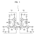
- Fig. 1 shows a basic construction of an optical communication apparatus according to the present invention.
- the optical communication apparatus 1 has plural transmitting units T X 1, T X 2, ..., and T X n; plural receiving units R X 1, R X 2, ..., and R X n; and a plastic optical fiber 4 for connecting the transmitting units and the receiving units.
- the transmitting unit T X n includes plural light emitting units 10 for emitting plural light beams having different wavelengths ⁇ 1 , ⁇ 2 , and ⁇ n , and plural optical demultiplexers 20A for performing optical branching or multiplexing by reflecting or transmitting light beams emitting from the light emitting units 10.
- One of the optical demultiplexers 20A is connected to one end 4a of the single plastic optical fiber 4.
- the light beams emitted from the light emitting unit 10 pass into the end 4a and travel through the plastic optical fiber 4 to a remote site.
- Receiving units R X 1, R X 2, ..., and R X n are provided at the other end 4b of the plastic optical fiber 4.
- the receiving unit R X n includes plural light receiving units 31, each individually having selectivity to one of the light beams of wavelengths ⁇ 1 , ⁇ 2 , ..., and ⁇ n and plural optical demultiplexers 20B for branching, to each of plural light receiving units 31, a light beam in each predetermined wavelength band from the entire spectrum band.
- plural transmitting units T X 1, T X 2, ..., and T X n and plural receiving units, R X 1, R X 2, ..., and R X n are provided at ends of the plastic optical fiber 4 so that both the transmitting units and the receiving units have selectivity for each of wavelengths ⁇ 1 , ⁇ 2 , ..., and ⁇ n in one-to-one correspondence.
- the transmitting unit T X 1 (one member of the pair) includes light emitting units 10 for emitting light beams of four different wavelengths, the optical demultiplexer 20A for allowing a light beam in only a predetermined wavelength band to be reflected or transmitted, and plastic optical fibers 30a and 30b for conveying light beams therethrough.
- the light emitting unit 10 has the light sources, including a light emitting element 12 (blue LED) for emitting a blue light beam ( ⁇ b approximately 470 nm), a light emitting element 14 (green LED) for emitting a green light beam ( ⁇ g approximately 525 nm), a light emitting element 16 (red LED) for emitting a red light beam ( ⁇ r approximately 650 nm) and a light emitting element 18 (infrared LED) for emitting a near infrared light beam ( ⁇ ir approximately 850 nm).
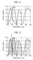
- Light emitting elements 12, 14, 16, and 18 are made of LEDs having good response-characteristics. As shown in Fig. 2, the emission spectrum of the output light beams therefrom has peak values in the blue range, the green range, the red range, and the near infrared range, and is substantially normally distributed. The output light beams have optical power highly concentrated along the optical axis. Moreover, light emitting elements 12, 14, 16, and 18 have the ability to show, as an optical signal, information represented by an electrical signal, such as on-off condition of a power supply thereof, and a digital signal. The output signal is output as an optical signal by a driving control device (not shown).
- the optical demultiplexer 20A includes a branching filter 22a reflecting light at blue wavelengths (around 480 nm) and transmitting light at other wavelengths, such as at green wavelengths; a branching filter 24a transmitting light at red wavelengths and reflecting light at other wavelengths (750 to 900 nm), such as at infrared wavelengths; and a branching filter 26a reflecting light at blue and green wavelengths (450 to 560 nm) and transmitting light at other wavelengths, such as at red and infrared wavelengths.
- a branching filter 22a reflecting light at blue wavelengths (around 480 nm) and transmitting light at other wavelengths, such as at green wavelengths
- a branching filter 24a transmitting light at red wavelengths and reflecting light at other wavelengths (750 to 900 nm), such as at infrared wavelengths
- a branching filter 26a reflecting light at blue and green wavelengths (450 to 560 nm) and transmitting light at other wavelengths, such as at red and infrare
- the branching filter 22a has three mounting holes in the casing thereof. Light emitting elements 12 and 14 are fixed at two mounting holes so that each of the two mounting holes is disposed perpendicular to the optical axis of the corresponding light emitting element, and one end of the plastic optical fiber 30a is removably fixed at the remaining mounting hole.
- the branching filter 24a has three mounting holes in the casing thereof.
- the light emitting elements 16 and 18 are fixed at two mounting holes so that each of the two mounting holes is disposed perpendicular to the optical axis of the corresponding light emitting element, and one end of the plastic optical fiber 30b is removably fixed at the remaining mounting hole.
- red LED red LED
- infrared light emitted from the light emitting element 18 is reflected then they travel to one end of the plastic optical fiber 30b.
- the branching filter 26a has three mounting holes in the casing thereof.
- the other end of the plastic optical fiber 30a, the other end of the plastic optical fiber 30b, and one end of the plastic optical fiber 4 are removably mounted at the three mounting holes, respectively.
- the branching filter 26a reflects blue and green light incident through the plastic optical fiber 30a from light emitting elements 12 and 14, and transmits red and infrared light, incident through the plastic optical fiber 30b from light emitting elements 16 and 18.
- the above branching filters 22a, 24a, and 26a are disposed at optical demultiplexing points for demultiplexing light beams or in optical multiplexing points for multiplexing light beams.
- the above plastic optical fibers 4, 30a, and 30b are made of plastic and are thin long wires of diameter approximately 0.75 to 1 mm in the direction of the thickness. Additionally, the plastic optical fiber includes a core, made of polymethyl methacrylate (PMMA), formed in the center of the plastic optical fiber, and a cladding, made of transparent resin, such as polyethylene, formed in the periphery and surrounding the core.
- PMMA polymethyl methacrylate
- a cladding made of transparent resin, such as polyethylene
- Plastic optical fibers 4, 30a, and 30b of the present invention employ inexpensive, thick-core diameter, and easy-to-use step-index optical fibers (SI).
- a step-index fiber is a fiber in which the refractive index of the core changes stepwise in the radial direction, and is a multiple-mode-type containing multiple light beams, each traveling at a different speed.
- the receiving unit R X 1 includes the light receiving units 31 for receiving light of four different wavelengths, the optical demultiplexers 20B producing a branched light beam at a predetermined wavelength band by reflecting or transmitting light, plastic optical fibers 30c and 30d conducting the light beams therethrough.
- the light receiving unit 31 includes light receiving elements 32, 34, 36, and 38.
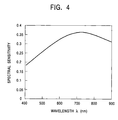
- the light receiving elements are made of PIN photodiodes, have good directional characteristics and have relatively broad spectral sensitivity characteristics for light emitted from light emitting elements 12, 14, 16, and 18.
- the optical demultiplexer 20B (second branching filter) includes branching filters 22b, 24b, and 26b.
- the branching filter 22b has three mounting holes in the casing thereof. Light receiving elements 32 and 34 are fixed at two mounting holes, and one end of the plastic optical fiber 30c is removably fixed at the remaining mounting hole. Moreover, the branching filter 22b allows light conveyed to the end of the plastic optical fiber 30c to branch to light receiving elements 32 and 34.
- the branching filter 22b is a band-pass filter (BPF) which reflects light in wavelength of only approximately 480 nm and transmits light at other wavelengths.
- BPF band-pass filter
- the branching filter 24b has three mounting holes in the casing thereof. Light receiving elements 36 and 38 are fixed at two mounting holes, and one end of the plastic optical fiber 30d is removably fixed at the remaining mounting hole. Moreover, the branching filter 24b allows light conducted to the end of the plastic optical fiber 30d to branch to light receiving elements 36 and 38.
- the branching filter 24b transmits only light at wavelengths between approximately 750 and 900 nm and reflects light at other wavelengths.
- the branching filter 26b has three mounting holes in the casing thereof. Other ends of the plastic optical fibers 30c, 30d, 4 are removably fixed at the three mounting holes.
- the branching filter 26b reflects blue and green light, incident through the plastic optical fiber 4 from light emitting elements 12 and 14, and transmits red and infrared light, incident through the plastic optical fiber 4 from light emitting elements 16 and 18.
- the branching filter 26b reflects only light at wavelengths between approximately 450 to 560 nm and transmits light at other wavelengths.
- Plastic optical fibers 30c and 30d are the same as plastic optical fibers 4, 30a, and 30b.
- the optical communication apparatus 1 performs optical communication as follows.
- Blue light ( ⁇ b approximately 475 nm) is emitted from the light emitting element (blue LED) 12, is reflected in the branching filter 22a where light at wavelengths of around 480 nm is reflected, and is incident on one end of the plastic optical fiber 30a.
- the branching filter 22a branches light at predetermined wavelengths (the shaded portion indicated by "X" in Fig. 3) as branched light beam ( ⁇ bl ) from light beam ( ⁇ b ) at blue wavelengths.
- the blue branched light beam ⁇ bl travels through the plastic optical fiber 30a, and is incident on the branching filter 26a which is connected to the other end of the plastic optical fiber 30a. Since the branching filter 26a reflects light at wavelengths of 450 to 560 nm, the blue branched light beam ⁇ bl is reflected at the branching filter 26a and is incident on one end of the plastic optical fiber 4 which is disposed perpendicular to the optical axis of the plastic optical fiber 30a.
- the blue branched light beam ⁇ bl is transmitted through the plastic optical fiber 4, and is incident on the branching filter 26b through the other end of the plastic optical fiber 4. Since the branching filter 26b has the same construction as the branching filter 26a, the blue branched light beam ⁇ bl is reflected in the branching filter 26b, and is incident on one end of the plastic optical fiber 30c which is disposed perpendicular to the optical axis of the plastic optical fiber 30c. The blue branched light beam ⁇ bl is transmitted through the plastic optical fiber 30c, and is incident on the branching filter 22b through the other end of the plastic optical fiber 30c.
- the branching filter 22b since the branching filter 22b has the same construction as the branching filter 22a, the branching filter 22b reflects the blue branched light beam ⁇ bl to the light receiving element 32 where the blue branched light beam ⁇ bl is converted into an electric signal.
- green light ( ⁇ g approximately 525 nm) emitted from the light emitting element 14 (green LED), is of specifically reflected wavelengths around 480 nm
- the green light is transmitted through the branching filter 22a, and is incident on one end of the plastic optical fiber 30a.
- the branching filter 22a cuts off short wavelengths band which form the lower part from the curve indicated by "Y1" in Fig. 3, and transmits the remainder of the green light beam ⁇ g (Y1) which is the remainder of the emitted green light.
- the remaining green light beam ⁇ g (Y1) travels through the plastic optical fiber 30a and is incident on the branching filter 26a which is connected to the other end of the plastic optical fiber 30a.
- the branching filter 26a Since the branching filter 26a reflects light at wavelengths of 450 to 560 nm, light at long wavelengths in the remaining green light, which is the upper part from the curve indicated by "Y2" in Fig. 3, is allowed to be transmitted. Accordingly, the transmitted light is then reflected, as a green branched light beam ( ⁇ gl ), at the branching filter 26a, and is incident on one end of the plastic optical fiber 4.
- the green branched light beam ⁇ gl is transmitted through the plastic optical fiber 4, is incident on the branching filter 26b through the other end of the plastic optical fiber 4, is reflected in the branching filter 26b, and is incident on one end of the plastic optical fiber 30c which is disposed perpendicular to the optical axis of the plastic optical fiber 4.
- the green branched light beam ⁇ gl is transmitted through the plastic optical fiber 30c, and is reflected, by the branching filter 22b, from the other end of the plastic optical fiber 30c to the light receiving element 32 where the branched light beam is converted into an electrical signal.
- red light ( ⁇ r approximately 644 nm) and infrared light ( ⁇ ir approximately 850 nm) are emitted from the light emitting element 16 (red LED), and are incident on the branching filter 24a where red light beam is reflected through the plastic optical fiber 30b to the branching filter 26a while the infrared light is transmitted through the plastic optical fiber 30b to the branching filter 26a.
- the red and infrared light travel through the plastic optical fiber 26a, are transmitted through the plastic optical fiber 4 and the branching filter 26b, and are incident on the branching filter 24b through the plastic optical fiber 30d.
- the branching filter 24b reflects the light at wavelengths of 750 to 900 nm
- red light is incident on the light receiving element 36 as red branched light beam ⁇ rl without substantial modification of the emitted light from the light emitting element 16 (red LED) (Fig. 3).
- the infrared light beam is reflected at the branching filter 24b, and is incident on the light receiving element 38 as a infrared branched light beam ⁇ irl without substantial modification of the emitted light beam in the wavelengths from the light emitting element 18 (infrared LED).
- the red and the infrared branched light beams are converted into electrical signals at light receiving elements 36 and 38.
- the blue light beam, the green light beam, the red light beam, and the infrared light beam emitted from light emitting elements 12, 14, 16, and 18, respectively are received as branched light beams at light receiving elements 32, 34, 36, and 38, respectively, so that the wavelengths of the branched light beam do not overlap the others, whereby information sent by multiplexing the light beams as an optical signal and can be accurately received at a remote location.
- the half-width of each branched light beam may be increased so that greater branched light intensity is gained at longer wavelengths, at which transmission loss is greater.
- the branched light intensity characteristics of each branching filter is set so that the branched light intensity characteristics are optimized.
- optical waveguides may be used instead of plastic optical fibers 30a, 30b, 30c, and 30d.
- the light emitting unit 10 has four light emitting elements for emitting light at different wavelengths, and in which the light receiving unit 31 receives branched light only in wavelengths in which little or no cross talk occurs.
- Table 1 illustrates fiber loss ⁇ 1, the optical outputs of four different light emitting elements 12, 14, 16, and 18, spectral sensitivity characteristics ⁇ 1 of light receiving elements 32, 34, 36, and 38, the output from the end of the fiber on the side of each light emitting element 12, 14, 16, and 18, the transmittance/reflectance T 1 of each branching filter, the final output (the output from a light receiving element after a light beam is incident on the light receiving element through a fiber), and leakage light (loss due to dispersion of light) for the wavelength band of 400 to 900 nm, namely the range of the wavelengths ⁇ of visible light and infrared light.
- the coating thickness of each branching filter is set so as to have optimal transmittance/reflectance T 1 .
- the transmission loss should be maintained to be equal to or less than 20 dB (1 percent of the transmittance) when a signal is transferred in a single optical (plastic) fiber without using a repeater.
- it is desirable for the transmittance loss is desirable to be maintained to be equal to or less than 10 dB.
- ⁇ P(nleak) represents the total amount of the leaked light at all wavelengths.
- Table 1 shows optimized results obtained by applying the optimal design to the branching filters to obtain the total amount P(total) which has the final output P(n) with low light transmission loss at each light receiving unit.
- Fig. 6 shows one example of the optimized results in which, in order to optically communicate by causing light of each wavelength to carry information employing the blue LED ( ⁇ b : 470 nm), the green LED ( ⁇ g : 525 nm), a yellow LED ( ⁇ y : 570 nm), and the red LED ( ⁇ r : 644 nm), the branching filters split the wavelength band into a number of predetermined regions so that the wavelength band of each light beam does not overlap the others.
- the branching filters split the wavelength band into a number of predetermined regions so that the wavelength band of each light beam does not overlap the others.
- the optical communication apparatus having a transmitting unit emitting light of four different wavelengths is constructed in the same way as the basic construction shown in Fig. 1, except that a light emitting element (yellow LED) 18a for emitting yellow light, instead of the light emitting element (infrared LED) 18, is used.
- a light receiving element 38a i.e., the counterpart of the light emitting element 18a, is provided in the light receiving unit 31.
- a normal-distribution is formed in a narrow wavelength band where the peak wavelengths of each light, as shown in Fig. 6, are 465 nm, 520 nm, 565 nm, and 645 nm, and the half-width of each dominant wavelength is maintained within 30 nm.
- the peak wavelengths of each light as shown in Fig. 6, are 465 nm, 520 nm, 565 nm, and 645 nm, and the half-width of each dominant wavelength is maintained within 30 nm.
- each light produces an nth harmonic component, the value of the nth harmonic component is of a nearly negligible quantity.
- optical communication can be performed without risk of cross talk, regardless of the drift of the wavelength band (the shift in the peak of the wavelength) caused by changes in a power supply for a light emitting element.
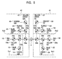
- the optical communication apparatus having eight emitting wavelengths, includes a transmitting unit 40 having light emitting elements for emitting light beams of eight different wavelengths, the plastic optical fiber 4 connecting one end thereof to a part of the transmitting unit 40 for conducting light emitted from the transmitting unit 40, and a receiving unit 41 connected to the other end of the plastic optical fiber 4 having light receiving elements for converting an optic signal into an electrical signal.
- the transmitting unit 40 includes a first transmitting unit T X 1, a second transmitting unit T X 2, and a branching filter 58a connected to the first and the second transmitting units T X 1 and T X 2.
- the receiving unit 41 includes a first receiving unit R X 1, a second receiving unit R X 2, and a branching filter 58b connected to the first and the second receiving units R X 1 and R X 2.
- the first transmitting unit T X 1 has the same construction as the counterpart T X 1 in the optical communication apparatus having four emitting wavelengths in the first embodiment.
- the first receiving unit R X 1 has the same construction as the that the counterpart R X 1 in the first embodiment.
- the transmitting unit T X 2 basically has the same construction as the transmitting unit T X 1, and likewise, the receiving unit R X 2 basically has the same construction as the receiving unit R X 1. The differences are the employing emitting wavelengths of transmitting units T X 1 and T X 2, the employing receiving wavelengths of receiving units R X 1 and R X 2, and spectral sensitivity characteristics of the branching filters of T X 1 and T X 2 as well as the branching filters of R X 1 and R X 2.
- the transmitting unit T X 2 includes a light emitting element (violet LED) 43 emitting violet light ( ⁇ v 445 nm), a light emitting element (blue green LED) 45 emitting blue green light ( ⁇ bg 500 nm), a light emitting element (yellow green LED) 47 emitting yellow green light ( ⁇ yg 550 nm), a light emitting element (orange LED) 49 emitting orange light ( ⁇ or 600 nm), a branching filter 52a having light emitting elements 43 and 45 mounted thereon, a branching filter 54a having light emitting elements 47 and 49 mounted thereon, and a branching filter 56a connected through a plastic optical fiber 60a to the branching filter 52a and connected through a plastic optical fiber 60b to the branching filter 54a.
- a branching filter 52a having light emitting elements 43 and 45 mounted thereon
- a branching filter 54a having light emitting elements 47 and 49 mounted thereon
- a branching filter 56a connected through a plastic optical fiber
- the branching filter 52a transmits only light at violet light wavelength ( ⁇ v 445 nm) into the casing thereof, and reflects light at other wavelengths.
- the branching filter 54a transmits only light at yellow green light wavelength ( ⁇ yg 550 nm) into the casing thereof, and reflects light at other wavelengths.
- the branching filter 56a transmits only light at wavelengths of 420 to 520 nm into the casing thereof, and reflects light at other wavelengths.
- the branching filter 58a reflects light at wavelengths of the violet light ( ⁇ v 445 nm), blue green light ( ⁇ bg 500 nm), yellow green light ( ⁇ yg 550 nm), and orange light ( ⁇ or 600 nm), and transmits blue light ( ⁇ b 470 nm), green light ( ⁇ g 525 nm), yellow light ( ⁇ y 570 nm), and red light ( ⁇ r 650 nm).
- the R X 2 includes light receiving elements 53, 55, 57, and 59, which are composed of PIN photo diodes, a branching filter 52b having light receiving elements 53 and 55 mounted thereon, a branching filter 54b having light receiving elements 57 and 59 mounted thereon, a branching filter 56b connected through a plastic optical fiber 60c to the branching filter 52b and connected through 60d to the branching filters 54b.
- Branching filters 52b, 54b, and 56b have the same construction as branching filters 52a, 54a, and 56a.
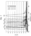
- Fig. 7 shows wavelength distribution characteristics of the optical communication apparatus having eight emitting wavelengths.
- each peak value of the optical outputs there are eight peak values of the optical outputs, i.e. the violet light ( ⁇ v 445 nm), the blue light ( ⁇ b 470 nm), the blue green light (( ⁇ bg 500 nm), the green light ( ⁇ g 525 nm), the yellow green light ( ⁇ yg 550 nm), the yellow light ( ⁇ y 570 nm), the orange light ( ⁇ or 600 nm), and the red light ( ⁇ r 650 nm).
- the half-width of each peak value is equal to or less than 30 nm, whereby a wavelength normal distribution curve is formed in which each optical output having the peak value does not overlap the others.
- the optical communication is performed with little or no cross talk.
- the optical communication apparatuses having four different emitting wavelengths and eight different emitting wavelengths have been described.
- the number of the emitting wavelengths of the optical communication apparatus is not necessarily four or eight.
- two or three light emitting elements may be used for the optical communication apparatus.
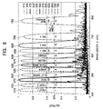
- Fig. 8 shows wavelength distribution characteristics of the optical communication apparatus having twelve emitting wavelengths. Four more peaks are provided so as to cover between each peak in the wavelength distribution in Fig. 7. The half-width of each peak value is not more than 30 nm so that the cross talk owing to light at each wavelength is prevented.
- Twelve branched light beams branched by branching filters are received, respectively, from shorter wavelengths to longer wavelengths in order of violet 1, violet 2, blue, blue green, green, yellow green, yellow, orange, red 1, red 2, red 3, and near infrared.
- optical communication apparatus uses four, eight, or furthermore twelve predetermined emitting wavelengths, extra light emitting elements can be easily added and connected via branching filters and plastic optical fibers thereto.
- bus signals corresponding to the light emitting elements increases, for example from 4 to 8, and furthermore to 12, more peaks are provided so as to cover between each peak of the dominant wavelengths of the branched light. Therefore, selectivity for each light at wavelengths increases. In addition, workability is greatly improved in the case of connecting the light emitting elements to bus signals.
- the emitting light wavelengths range between 400 nm and 900 nm, which lie within a wavelength range of visible light and near infrared light.
- visible light 400 nm to 700 nm
- a greater number of electrical devices can be connected to the optical communication apparatus.
- an optical communication apparatus may include a transmitting unit having light emitting elements 16 and 18, branching filters 24a and 26a and the plastic optical fiber 30b; the plastic optical fiber 4; and a receiving unit having light receiving elements 36 and 38, branching filters 24b and 26b, and the plastic optical fiber 30d. Therefore, the optical communication apparatus having two emitting wavelengths is obtained whereby a combination of a plural of the above optical communication apparatuses may be used.
Landscapes
- Physics & Mathematics (AREA)
- General Physics & Mathematics (AREA)
- Optics & Photonics (AREA)
- Optical Communication System (AREA)
- Optical Couplings Of Light Guides (AREA)
Applications Claiming Priority (2)
| Application Number | Priority Date | Filing Date | Title |
|---|---|---|---|
| JP11000340A JP2000199830A (ja) | 1999-01-05 | 1999-01-05 | 光通信装置 |
| JP34099 | 1999-01-05 |
Publications (2)
| Publication Number | Publication Date |
|---|---|
| EP1018814A2 true EP1018814A2 (fr) | 2000-07-12 |
| EP1018814A3 EP1018814A3 (fr) | 2005-08-10 |
Family
ID=11471158
Family Applications (1)
| Application Number | Title | Priority Date | Filing Date |
|---|---|---|---|
| EP00100104A Withdrawn EP1018814A3 (fr) | 1999-01-05 | 2000-01-04 | Dispositif de communication optique |
Country Status (3)
| Country | Link |
|---|---|
| EP (1) | EP1018814A3 (fr) |
| JP (1) | JP2000199830A (fr) |
| CN (1) | CN1259805A (fr) |
Cited By (2)
| Publication number | Priority date | Publication date | Assignee | Title |
|---|---|---|---|---|
| EP1211529A3 (fr) * | 2000-11-30 | 2004-07-28 | Toyoda Gosei Co., Ltd. | Procédé de fabrication d'un guide d'ondes optiques |
| WO2008080071A1 (fr) * | 2006-12-21 | 2008-07-03 | Embedded Control Systems | Procédé et appareil facilitant le multiplexage de la lumière dans un conduit optique partagé |
Families Citing this family (3)
| Publication number | Priority date | Publication date | Assignee | Title |
|---|---|---|---|---|
| CN102769856B (zh) * | 2011-05-06 | 2015-09-09 | 国民技术股份有限公司 | 一种光数据广播网络系统及方法 |
| JP7041485B2 (ja) * | 2017-10-05 | 2022-03-24 | 株式会社ヴィーネックス | ライン光源及びこれを備えた光ラインセンサユニット |
| US11496218B1 (en) * | 2021-05-03 | 2022-11-08 | Mellanox Technologies, Ltd. | Optical communication modules with improved security |
Family Cites Families (5)
| Publication number | Priority date | Publication date | Assignee | Title |
|---|---|---|---|---|
| US5774606A (en) * | 1996-05-17 | 1998-06-30 | Lucent Technologies, Inc. | Optical fiber transmission system with a passive optical router |
| JP3325459B2 (ja) * | 1996-06-06 | 2002-09-17 | 沖電気工業株式会社 | 光フィルタモジュールならびに光増幅装置および光送受信装置 |
| CN1060572C (zh) * | 1996-11-13 | 2001-01-10 | 陈祖培 | 熔锥型高密度波分复用器 |
| JPH11234217A (ja) * | 1998-02-10 | 1999-08-27 | Alps Electric Co Ltd | 波長多重光通信装置 |
| JPH11266234A (ja) * | 1998-03-16 | 1999-09-28 | Alps Electric Co Ltd | 光通信装置 |
-
1999
- 1999-01-05 JP JP11000340A patent/JP2000199830A/ja not_active Withdrawn
-
2000
- 2000-01-03 CN CN00100011.XA patent/CN1259805A/zh active Pending
- 2000-01-04 EP EP00100104A patent/EP1018814A3/fr not_active Withdrawn
Cited By (3)
| Publication number | Priority date | Publication date | Assignee | Title |
|---|---|---|---|---|
| EP1211529A3 (fr) * | 2000-11-30 | 2004-07-28 | Toyoda Gosei Co., Ltd. | Procédé de fabrication d'un guide d'ondes optiques |
| EP1533635A1 (fr) * | 2000-11-30 | 2005-05-25 | Toyoda Gosei Co., Ltd. | Module de transmission et réception optique |
| WO2008080071A1 (fr) * | 2006-12-21 | 2008-07-03 | Embedded Control Systems | Procédé et appareil facilitant le multiplexage de la lumière dans un conduit optique partagé |
Also Published As
| Publication number | Publication date |
|---|---|
| JP2000199830A (ja) | 2000-07-18 |
| CN1259805A (zh) | 2000-07-12 |
| EP1018814A3 (fr) | 2005-08-10 |
Similar Documents
| Publication | Publication Date | Title |
|---|---|---|
| Miki et al. | Viabilities of the wavelength-division-multiplexing transmission system over an optical fiber cable | |
| EP0613263B1 (fr) | Réseau optique comportant un démultiplexeur de longueur d'onde compact | |
| CA2222845C (fr) | Liaison de donnees bidirectionnelles monofibre peu couteuse | |
| JPH11507738A (ja) | オプトエレクトロニクス回路 | |
| CN109416439A (zh) | 光检测器与解复用器输出的直接光耦合技术及使用该技术的光收发器 | |
| KR20190050715A (ko) | 양방향 다파장 기가비트 광섬유 네트워크 | |
| WO2018170828A1 (fr) | Ensemble optique bidirectionnel, unité de réseau optique, terminal de ligne optique et système de réseau optique passif | |
| TWM484713U (zh) | 可替換式光發射模組及搭載有可替換式光發射模組的光收發器 | |
| US7309169B2 (en) | Single-channel communication device for optical fibre | |
| EP3988974A1 (fr) | Puce de modulation et module d'émission de lumière | |
| CN210864119U (zh) | 多通道并行光模块 | |
| CN107592160A (zh) | 用于可选择并行光纤和波分复用操作的方法和系统 | |
| Laude et al. | Wavelength division multiplexing/demultiplexing (WDM) using diffraction gratings | |
| JPH0541963B2 (fr) | ||
| US6321001B1 (en) | Wavelength division multiplexed optical communication system | |
| US9383528B2 (en) | Light-receiving module | |
| CN111147961B (zh) | 垂直腔面发射激光器(vcsel)的双频带波分复用(wdm)链路 | |
| EP1202480A2 (fr) | Système de communication à fibre optique bidirectionnel, dispositif de communication et émetteur-récepteur | |
| US6591042B2 (en) | Fiber based wavelength de-multiplexing system | |
| EP0153722A3 (fr) | Multiplexeur-démultiplexeur hybride optique de longueurs d'onde | |
| EP1018814A2 (fr) | Dispositif de communication optique | |
| CN210427856U (zh) | 一种10g cwdm 18通道单纤双向光器件 | |
| EP1250772B1 (fr) | Reseau permettant la distribution de signaux a une pluralite d'utilisateurs | |
| JP5071870B2 (ja) | 光路切替型光信号送受信装置および光信号の光路切替方法 | |
| US6295150B1 (en) | Wavelength division multiplexing device |
Legal Events
| Date | Code | Title | Description |
|---|---|---|---|
| PUAI | Public reference made under article 153(3) epc to a published international application that has entered the european phase |
Free format text: ORIGINAL CODE: 0009012 |
|
| AK | Designated contracting states |
Kind code of ref document: A2 Designated state(s): AT BE CH CY DE DK ES FI FR GB GR IE IT LI LU MC NL PT SE |
|
| AX | Request for extension of the european patent |
Free format text: AL;LT;LV;MK;RO;SI |
|
| PUAL | Search report despatched |
Free format text: ORIGINAL CODE: 0009013 |
|
| AK | Designated contracting states |
Kind code of ref document: A3 Designated state(s): AT BE CH CY DE DK ES FI FR GB GR IE IT LI LU MC NL PT SE |
|
| AX | Request for extension of the european patent |
Extension state: AL LT LV MK RO SI |
|
| AKX | Designation fees paid | ||
| STAA | Information on the status of an ep patent application or granted ep patent |
Free format text: STATUS: THE APPLICATION IS DEEMED TO BE WITHDRAWN |
|
| 18D | Application deemed to be withdrawn |
Effective date: 20060211 |
|
| REG | Reference to a national code |
Ref country code: DE Ref legal event code: 8566 |