EP1018842A2 - Projecteur vidéo - Google Patents
Projecteur vidéo Download PDFInfo
- Publication number
- EP1018842A2 EP1018842A2 EP00250003A EP00250003A EP1018842A2 EP 1018842 A2 EP1018842 A2 EP 1018842A2 EP 00250003 A EP00250003 A EP 00250003A EP 00250003 A EP00250003 A EP 00250003A EP 1018842 A2 EP1018842 A2 EP 1018842A2
- Authority
- EP
- European Patent Office
- Prior art keywords
- light
- denotes
- reflection type
- lens
- modulation elements
- Prior art date
- Legal status (The legal status is an assumption and is not a legal conclusion. Google has not performed a legal analysis and makes no representation as to the accuracy of the status listed.)
- Withdrawn
Links
- 230000003287 optical effect Effects 0.000 claims abstract description 161
- 210000001747 pupil Anatomy 0.000 claims description 16
- 230000003247 decreasing effect Effects 0.000 description 6
- 239000003086 colorant Substances 0.000 description 5
- 238000005286 illumination Methods 0.000 description 5
- 238000002834 transmittance Methods 0.000 description 4
- 239000011159 matrix material Substances 0.000 description 2
- 230000005540 biological transmission Effects 0.000 description 1
- 239000011247 coating layer Substances 0.000 description 1
- 230000007423 decrease Effects 0.000 description 1
- 238000001704 evaporation Methods 0.000 description 1
- 239000011521 glass Substances 0.000 description 1
- 229910052736 halogen Inorganic materials 0.000 description 1
- 150000002367 halogens Chemical class 0.000 description 1
- 230000001678 irradiating effect Effects 0.000 description 1
- 239000004973 liquid crystal related substance Substances 0.000 description 1
- QSHDDOUJBYECFT-UHFFFAOYSA-N mercury Chemical compound [Hg] QSHDDOUJBYECFT-UHFFFAOYSA-N 0.000 description 1
- 229910052753 mercury Inorganic materials 0.000 description 1
- 229910001507 metal halide Inorganic materials 0.000 description 1
- 150000005309 metal halides Chemical class 0.000 description 1
- 238000000034 method Methods 0.000 description 1
- 239000011347 resin Substances 0.000 description 1
- 229920005989 resin Polymers 0.000 description 1
- 238000007789 sealing Methods 0.000 description 1
- 229910052724 xenon Inorganic materials 0.000 description 1
- FHNFHKCVQCLJFQ-UHFFFAOYSA-N xenon atom Chemical compound [Xe] FHNFHKCVQCLJFQ-UHFFFAOYSA-N 0.000 description 1
Images




Classifications
-
- H—ELECTRICITY
- H04—ELECTRIC COMMUNICATION TECHNIQUE
- H04N—PICTORIAL COMMUNICATION, e.g. TELEVISION
- H04N9/00—Details of colour television systems
- H04N9/12—Picture reproducers
- H04N9/31—Projection devices for colour picture display, e.g. using electronic spatial light modulators [ESLM]
- H04N9/3102—Projection devices for colour picture display, e.g. using electronic spatial light modulators [ESLM] using two-dimensional electronic spatial light modulators
- H04N9/3105—Projection devices for colour picture display, e.g. using electronic spatial light modulators [ESLM] using two-dimensional electronic spatial light modulators for displaying all colours simultaneously, e.g. by using two or more electronic spatial light modulators
-
- H—ELECTRICITY
- H04—ELECTRIC COMMUNICATION TECHNIQUE
- H04N—PICTORIAL COMMUNICATION, e.g. TELEVISION
- H04N5/00—Details of television systems
- H04N5/74—Projection arrangements for image reproduction, e.g. using eidophor
- H04N5/7416—Projection arrangements for image reproduction, e.g. using eidophor involving the use of a spatial light modulator, e.g. a light valve, controlled by a video signal
- H04N5/7458—Projection arrangements for image reproduction, e.g. using eidophor involving the use of a spatial light modulator, e.g. a light valve, controlled by a video signal the modulator being an array of deformable mirrors, e.g. digital micromirror device [DMD]
Definitions
- the present invention relates to a video projector.
- the invention relates to a video projector using a reflection type optical modulation element.
- Video projectors for projecting an image in accordance with a received video signal are known.
- Video projectors is one using a transmission type optical modulation element such as an LCD (Liquid Crystal Display) panel or the like and one using a reflection type optical modulation element such as a DMD (Digital Micromirror Device: a trademark of Texas Instruments, Incorporated) or the like.
- a transmission type optical modulation element such as an LCD (Liquid Crystal Display) panel or the like
- a reflection type optical modulation element such as a DMD (Digital Micromirror Device: a trademark of Texas Instruments, Incorporated) or the like.
- DMD Digital Micromirror Device: a trademark of Texas Instruments, Incorporated
- Fig. 6 is a side view showing the structure of a video projector as a first conventional example.
- Fig. 7 is a sectional plan view taken along a line VI-VI in Fig. 6.
- the light exiting from the rod-shaped optical integrator 103 sequentially passes through relay lenses 104a-104c, reflected by a reflecting mirror 105, passes through a relay lens 104d, and then reflected by the bonding surface of wedge-shaped prisms 106a and 106b that configure a reflecting prism 106.
- the light reflected by the reflecting prism 106 is separated by color prisms 107R, 107G, and 107B into red light, green light, and blue light, respectively, which enter DMDs (Digital Micromirror Device: a trademark of Texas Instruments, Incorporated) 109R, 109G, and 109B, respectively.
- DMDs Digital Micromirror Device: a trademark of Texas Instruments, Incorporated
- the DMDs 109R, 109G, and 109B are supplied with video signals corresponding to red, green, and blue components, respectively.
- the reflectance values of the incident light beams are controlled on a pixel-by-pixel basis in accordance with those video signals.
- the full-colored image light passes through the reflecting prism 106 straightly and is then enlarged by a projecting lens 110.
- the light enlarged by the projecting lens 110 is projected onto a screen 111 as a projected image.
- Japanese Patent Laid-Open No. Hei 9-96867 (Laid-Open in Japan on April 8, 1997) discloses a video projector. The technique disclosed in this publication will be described below as a second conventional example.
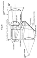
- Fig. 8 is a side view showing the structure of a video projector as a second conventional example.
- Fig. 9 is a plan view of the video projector of Fig. 8.
- the video projector shown in Figs. 8 and 9 has an optical radiating system 212, a tri-colored optical separating system 214, DMDs 216R, 216G, and 216B, and a projecting lens system 218.
- the optical radiating system 212 is composed of an optical source 220, a condenser lens 222, a mirror 224, and a prism 226.
- White-colored light emitted from the optical source 220 is condensed by the condenser lens 222, reflected by the mirror 224, again reflected by the prism 226, and then enters the tri-colored optical separating system 214.
- the white-colored light entering the tri-colored optical separating system 214 is separated by prisms 228R, 228G, and 228B into red light, green light, and blue light, respectively, which enter the DMDs 216R, 216G, and 216B that are disposed behind the respective prisms 228R, 228G, and 228B.
- Light beams reflected by the respective DMDs 216R, 216G, and 216B are combined by the prisms 228R, 228G, and 228B and then projected onto a front screen (not shown) by lenses 234 and 236 of the projecting lens system 218.
- the first conventional example first, since it is difficult to make the diameter of a light beam sufficiently small at the pupil position 110p of the projecting lens 110, it is impossible to cause all of light beams emitted from the optical source 101 to pass to the pupil position 110p of the projecting lens 110 without undue loss of light, resulting in a problem that a high-brightness, high-contrast projected image cannot be obtained.
- An object of the present invention is therefore to provide a video projector using a reflection type optical modulation element whose lens system is simple in configuration and which can produce a high-brightness, high-contrast projected image.
- a video projector having an optical source for radiating light; a reflecting mirror for reflecting the light radiated by the optical source as a reflected light beam moves along a particular optical axis; a converting optical system for converting the profile of the reflected light beam from the reflecting mirror; a plurality of color prisms for wavelength-separating the converted-light from the converting optical system into a plurality of colored light beams; a plurality of reflection type optical modulation elements for selectively reflecting each of the colored light beams from the color prisms on a pixel-pixel basis in accordance with each of received video signals, respectively; a projecting lens for projecting light obtained through wavelength-combining, by the color prisms, of light beams reflected by each of the reflection type optical modulation elements; and a plurality of condenser lenses disposed between the color prisms and the reflection type optical modulation elements, respectively.
- the video projector in the video projector according to the first aspect, further having a relay lens disposed between the converting optical system and the color prisms.
- the condenser lenses corresponding to the respective colors are disposed immediately before the reflection type optical modulation elements corresponding to the respective colors. Therefore, the diameter of a light beam at the pupil position of the projecting lens can be decreased sufficiently, and hence all of a light beam emitted from the optical source can be used effectively without undue loss of light. Further, since the number of lenses configuring the lens system disposed between the optical source and the reflection type optical modulation elements can be reduced; the light transmittance can be kept high. As a result, the brightness and the contrast of a projected image on the screen can be increased.
- the video projector can be miniaturized.
- the converting optical system has a rod-shaped optical integrator.
- the rod-shaped optical integrator is used as the converting optical system
- (1) the image on the outgoing surface of the rod-shaped optical integrator is converged on the reflection type optical modulation elements without undue loss of light
- (2) the image on the incident surface of the rod-shaped optical integrator is converted into a small cross-section at the pupil position of the projecting lens. Therefore, all of light beams emitted from the optical source can be used effectively without undue loss of light.
- the number of lenses configuring the lens system disposed between the optical source and the reflection type optical modulation elements can be reduced, the light transmittance can be kept high. As a result, the brightness and the contrast of the projected image on the screen can be increased.
- the video projector can be miniaturized.
- the converting optical system has first and second fly-eyed lenses.
- the image on the outgoing surface of the second fly-eyed lens is converged on the reflection type optical modulation elements without undue loss of light
- the image on the incident surface of the first fly-eyed lens is converted into a small cross-section at the pupil position of the projecting lens. Therefore, all of a light beam emitted from the optical source can be used effectively without undue loss of light. Further, since the number of lenses configuring the lens system disposed between the optical source and the reflection type optical modulation elements can be reduced; the light transmittance can be kept high. As a result, the brightness and the contrast of a projected image on the screen can be increased.
- the video projector can be miniaturized.
- the video projector includes an optical source 1, a reflecting mirror 2, a rod-shaped optical integrator 3, a relay lens 4, a reflecting mirror 5, a reflecting prism 6, color prisms 7R, 7G, and 7B, condenser lenses 8R, 8G, and 8B, reflection type optical modulation elements 9R, 9G, and 9B, and a projecting lens 10.
- the optical source 1 is a white-colored optical source such as a high-pressure mercury lamp. Alternatively, it may be an arbitrary white-colored optical source such as a metal halide lamp, a xenon lamp, or a halogen lamp.
- the reflecting mirror 2 which is an elliptical surface mirror, converts light that is radiated from the optical source 1 to all directions into parallel light going along a particular optical axis and outputs the parallel light.
- the rod-shaped optical integrator 3 is an optical element formed by, for example, evaporating a dielectric multilayered film onto an incident surface 3a and an outgoing surface 3b that are both end surfaces of a rod-shaped glass member.
- the light coming from the reflecting mirror 2 incident onto the incident surface 3a is reflected plural times by the semi-transparent films and then is output from the outgoing surface 3b, whereby the illumination intensity distribution of the light beam is uniformized over its entire cross-section.
- the relay lens 4 is an optical condensing element that condenses light exiting from the rod-shaped optical integrator 3 without dispersing it and inputs resulting condensed light to the reflection type optical modulation elements 9R, 9G, and 9B with high efficiency of light utilization.
- the reflecting mirror 5 is an optical element that reflects light that has passed through the relay lens 4 toward the reflecting prism 6.
- the reflecting mirror 5 is inclined with respect to the optical axis of incident light so as to irradiate light to the reflecting prism 6 perpendicularly to its incident surface.
- the reflecting prism 6 is an optical element for irradiating light to the reflection type optical modulation elements 9 at predetermined angles.
- the bonding surface of wedge-shaped prisms 6a and 6b is disposed at such an angle as to reflect, toward the color prisms 7R, 7G, and 7B, light that is reflected by the reflecting mirror 5.
- an air gap (not shown) is provided between the wedge-shaped prisms 6a and 6b so as to totally reflect incident light toward the color prisms 7R, 7G, and 7B. It is preferable that the width of the air gap is about 10 ⁇ m.
- the color prisms 7R, 7G, and 7B are optical elements that separate white-colored light coming from the reflecting prism 6 into red-colored light, green-colored light, and blue-colored light.
- the separated light beams of the three primary colors are incident onto the respective reflection type optical modulation elements 9R, 9G, and 9B.
- the color prisms 7R, 7G, and 7B are formed by bonding together wedge-shaped prisms 7R, 7G, and 7B.
- the bonding surfaces of the wedge-shaped prisms 7R, 7G, and 7B are formed with coating layers (not shown) that selectively reflect or transmit only a component of a red, green, or blue wavelength range.
- the condenser lenses 8R, 8G, and 8B which are disposed immediately before the respective reflection type optical modulation elements 9R, 9G, and 9B parallel with those, condense light beams exiting from the respective color prisms 7R, 7G, and 7B without dispersing those and irradiate as light beams to the respective reflection type optical modulation elements 9R, 9G, and 9B.
- Each of the reflection type optical modulation elements 9R, 9G, and 9B is any of various kinds of reflection type optical modulation elements such as a DMD (Digital Micromirror Device: a trademark of Texas Instruments, Incorporated).
- each of the reflection type optical modulation elements 9R, 9G, and 9B is configured in such a manner that a number of minute mirrors that are supported by flexible poles are arranged in matrix form.
- Video signals corresponding to the respective pixels are supplied to control electrodes that are disposed in the vicinity of the respective mirrors, whereby the reflecting surfaces of the respective mirrors are selectively deflected by electromagnetic force in accordance with whether a video signal corresponding to each pixel is supplied or not. In this manner, only selected mirrors reflect light beams toward the projecting lens 10.
- the projecting lens 10 is an optical element that enlarges and projects, as a projected image, onto a screen 11, light reflected by the reflection type optical modulation elements 9R, 9G, and 9B, combining in re-passage through the condenser lenses 8R, 8G, and 8B and the color prisms 7R, 7G, and 7B, and passage through the reflecting prism 6.
- a known focus adjusting mechanism (not shown) for focusing adjustment of the projected image or a known zooming mechanism (not shown) for adjusting the area of the projected image may be added to the projecting lens 10.
- the condenser lenses 8R, 8G, and 8B are disposed between the color prisms 7R, 7G, and 7B and the reflection type optical modulation elements 9R, 9G, and 9B, respectively, whereby light beams outgoing from the color prisms 7R, 7G, and 7B are incident onto the reflection type optical modulation elements 9R, 9G, and 9B, respectively, with high efficiency of light utilization.
- the light incident onto the incident surface 3a is reflected plural times in the rod-shaped optical integrator 3, and then output from the outgoing surface 3b of the rod-shaped optical integrator 3 in a state that its illumination intensity distribution is uniformized.
- the light exiting from the outgoing surface 3b of the rod-shaped optical integrator 3 is condensed by the relay lens 4, is reflected by the reflecting mirror 5, and then is irradiated on the incident surface of the reflecting prism 6 vertically.
- the light incident on the reflecting prism 6 is totally reflected by it and enters the color prisms 7R, 7G, and 7B, where the light is separated into light beams of the three primary colors, that is, red-colored light, green-colored light, and blue-colored light, which enter the respective condenser lenses 8R, 8G, and 8B.
- the condenser lenses 8R, 8G, and 8B are supported as independent parts between the color prisms 7R, 7G, and 7B and the reflection type optical modulation elements 9R, 9G, and 9B, respectively.
- the condenser lenses 8R, 8G, and 8B are supported as independent parts between the color prisms 7R, 7G, and 7B and the reflection type optical modulation elements 9R, 9G, and 9B, respectively.
- the condenser lenses 8R, 8G, and 8B may be made integral with the respective reflection type optical modulation elements 9R, 9G, and 9B by bonding the condenser lenses 8R, 8G, and 8B to the surfaces of the respective reflection type optical modulation elements 9R, 9G, and 9B, burying the condenser lenses 8R, 8G, and 8B in the respective reflection type optical modulation elements 9R, 9G, and 9B, or sealing the condenser lenses 8R, 8G, and 8B with resin or the like.
- the condenser lenses 8R, 8G, and 8B are so designed that (1) an image on the outgoing surface 3b of the rod-shaped optical integrator 3 is condensed onto the reflection type optical modulation elements 9R, 9G, and 9B without undue loss of light, and that (2) an image on the incident surface 3a of the rod-shaped optical integrator 3 is converted into a small-diameter cross-section at the pupil position 10p of the projecting lens 10.
- the rod-shaped optical integrator 3 the rod-shaped optical integrator 3
- d3 denotes the distance between the incident surface 3a of the rod-shaped optical integrator 3 and each of the condenser lenses 8R, 8G, and 8B
- d4 denotes the distance between each of the condenser lenses 8R, 8G, and 8B and the pupil position 10p of the projecting lens 10
- f3 denotes the focal length of each of the condenser lenses 8R, 8G, and 8B.
- Light beams condensed by the condenser lenses 8R, 8G, and 8B are irradiated on the reflection type optical modulation elements 9R, 9G, and 9B, respectively.
- the reflection type optical modulation elements 9R, 9G, and 9B reflect only incident light beams for video-signal-supplied pixels toward the projecting lens 10.
- the light beams reflected by the reflection type optical modulation elements 9R, 9G, and 9B again pass through the respective condenser lenses 8R, 8G, and 8B and are combined together by the color prisms 7R, 7G, and 7B. Resulting combined light carrying a full-colored image passes through the reflecting prism 6.
- the light passed through the reflecting prism 6 is enlarged by the projecting lens 10 and projected onto the screen 11.
- the condenser lenses 8R, 8G, and 8B are disposed between the color prisms 7R, 7G, and 7B and the reflection type optical modulation elements 9R, 9G, and 9B, respectively.
- the condenser lenses 8R, 8G, and 8B are so designed that (1) an image on the outgoing surface 3b of the rod-shaped optical integrator 3 is condensed onto the reflection type optical modulation elements 9R, 9G, and 9B without undue loss of light, and that (2) an image on the incident surface 3a of the rod-shaped optical integrator 3 is converted into a small-diameter cross-section at the pupil position 10p of the projecting lens 10. Therefore, all of light beams emitted from the optical source 1 can be incident onto the reflection type optical modulation elements 9R, 9G, and 9B with high efficiency of light utilization without undue loss of light, and hence the brightness of a projected image on the screen 11 can be increased.
- the diameters of incident light beams are made sufficiently small immediately before the reflection type optical modulation elements 9R, 9G, and 9B by the relay lens 4, the diameters of the respective condenser lenses 8R, 8G, and 8B can be made small. As a result, the lens system and hence the video projector can be miniaturized.
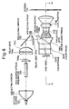
- Fig. 5 is showing a second embodiment of the present invention.
- This embodiment is configured in such a manner that the rod-shaped optical integrator 3 of the first embodiment is replaced by two fly-eyed lenses 23a and 23b. Since the other configurations of this embodiment are the same as the corresponding configuration of the first embodiment, Fig. 2 will also be referred to in the following description.
- Each of the fly-eyed lens 23a and 23b which is a lens (optical element) in which a number of minute lenses are arranged in matrix form on a plane, converts light beams incident on an incident surface 23a1 or 23b1 into light beams that are equivalent to light beams emitted from a number of minute optical sources, and outputs the resulting light beams from an outgoing surface 23a2 or 23b2.
- the condenser lenses 8R, 8G, and 8B are disposed between the color prisms 7R, 7G, and 7B and the reflection type optical modulation elements 9R, 9G, and 9B, respectively, whereby light beams exiting from the color prisms 7R, 7G, and 7B are incident onto the reflection type optical modulation elements 9R, 9G, and 9B, respectively, with high efficiency of light utilization.
- Light emitted from the optical source 1 is reflected by the reflecting mirror 2 and thereby converted into parallel light, which is irradiated on the incident surface 23a1 of the fly-eyed lens 23a.
- the light beam entering the fly-eyed lens 23a through the incident surface 23a1 is output from the outgoing surface 23a2 in a state that its illumination intensity distribution is uniformized over its entire cross-section.
- the light outgoing from the outgoing surface 23a2 enters the fly-eyed lens 23b through the incident surface 23b1 is output from the outgoing surface 23b2 in a state that its illumination intensity distribution is further uniformized.
- the light outgoing from the outgoing surface 23b2 of the fly-eyed lens 23b is condensed by the relay lens 4, is reflected by the reflecting mirror 5, and then irradiated on the reflecting prism 6 vertically.
- the incident light on the reflecting prism 6 is totally reflected by the bonding surface of the wedge-shaped prisms 6a and 6b and enters the color prisms 7R, 7G, and 7B, where the light is separated into light beams of the three primary colors, that is, red-colored light, green-colored light, and blue-colored light.
- An image on the outgoing surface 23b2 of the fly-eyed lens 23b is converged on the reflection type optical modulation elements 9R, 9G, and 9B by the respective condenser lenses 8R, 8G, and 8B.
- the condenser lenses 8R, 8G, and 8B are disposed between the color prisms 7R, 7G, and 7B and the reflection type optical modulation elements 9R, 9G, and 9B, respectively.
- the condenser lenses 8R, 8G, and 8B are so designed that (1) an image on the outgoing surface 23b2 of the fly-eyed lens 23b is condensed onto the reflection type optical modulation elements 9R, 9G, and 9B without undue loss of light, and that (2) an image on the incident surface 23a1 of the fly-eyed lens 23a is converted into a small-diameter cross-section at the pupil position 10p of the projecting lens 10.
- d3 denotes the distance between the fly-eyed lens 23b and each of the condenser lenses 8R, 8G, and 8B
- d4 denotes the distance between each of the condenser lenses 8R, 8G, and 8B and the pupil position 10p of the projecting lens 10
- f3 denotes the focal length of each of the condenser lenses 8R, 8G, and 8B.
- Light beams incident on the reflection type optical modulation elements 9R, 9G, and 9B are selectively reflected toward the projecting lens 10 on a pixel-by-pixel basis in accordance with received video signals.
- the reflected light beams again pass through the respective condenser lenses 8R, 8G, and 8B and then enter the respective color prisms 7R, 7G, and 7B.
- the light beams entering the respective color prisms 7R, 7G, and 7B are combined together by the color prisms 7R, 7G, and 7B. Resulting combined light carrying a full-colored image passes through the reflecting prism 6, is enlarged by the projecting lens 10, and is projected on the screen 11.
- the condenser lenses 8R, 8G, and 8B are disposed between the color prisms 7R, 7G, and 7B and the reflection type optical modulation elements 9R, 9G, and 9B, respectively.
- the condenser lenses 8R, 8G, and 8B are so designed that (1) an image on the outgoing surface 23b2 of the fly-eyed lens 23b is condensed onto the reflection type optical modulation elements 9R, 9G, and 9B without undue loss of light, and that (2) an image on the incident surface 23a1 of the fly-eyed lens 23a is converted into a small-diameter cross-section at the pupil position 10p of the projecting lens 10.
- the diameters of light beams are made sufficiently small immediately before the reflection type optical modulation elements 9R, 9G, and 9B by the relay lens 4, the diameters of the respective condenser lenses 8R, 8G, and 8B can be made small. As a result, the lens system and hence the video projector can be miniaturized.
- the condenser lenses 8R, 8G, and 8B may be provided in the manner of either Fig. 3 or Fig. 4.
- rod-shaped optical integrator 3 is used in the first embodiment and the fly-eyed lenses 23a and 23b are used in the second embodiment, an embodiment in which both of the rod-shaped optical integrator 3 and the fly-eyed lenses 23a and 23b are used and an embodiment in which neither of them are used are within the technical scope of the invention.
- rod-shaped optical integrator 3 Although one rod-shaped optical integrator 3 is used in the first embodiment and two fly-eyed lenses 23a and 23b are used in the second embodiment, the number of rod-shaped optical integrators or fly-eyed lenses may be determined arbitrarily.
- the brightness and the contrast of a projected image on the screen can be increased. This is because by virtue of the structure that the condenser lenses are disposed immediately before the respective reflection type optical modulation elements, light beams can be incident onto the reflection type optical modulation elements with high efficiency of light utilization without undue loss of light.
- the size of the video projector can be reduced. This is because the diameters of incident light beams are sufficiently decreased immediately before the reflection type optical modulation elements by the relay lens and hence the diameters of the condenser lenses can be decreased. Further, since the structure of relay lenses is simplified, the number of relay lenses can be reduced.
Landscapes
- Engineering & Computer Science (AREA)
- Multimedia (AREA)
- Signal Processing (AREA)
- Projection Apparatus (AREA)
- Microscoopes, Condenser (AREA)
- Transforming Electric Information Into Light Information (AREA)
- Video Image Reproduction Devices For Color Tv Systems (AREA)
Applications Claiming Priority (2)
| Application Number | Priority Date | Filing Date | Title |
|---|---|---|---|
| JP00295799A JP3372883B2 (ja) | 1999-01-08 | 1999-01-08 | プロジェクタ装置 |
| JP295799 | 1999-01-08 |
Publications (2)
| Publication Number | Publication Date |
|---|---|
| EP1018842A2 true EP1018842A2 (fr) | 2000-07-12 |
| EP1018842A3 EP1018842A3 (fr) | 2001-05-16 |
Family
ID=11543858
Family Applications (1)
| Application Number | Title | Priority Date | Filing Date |
|---|---|---|---|
| EP00250003A Withdrawn EP1018842A3 (fr) | 1999-01-08 | 2000-01-06 | Projecteur vidéo |
Country Status (3)
| Country | Link |
|---|---|
| US (1) | US6491398B2 (fr) |
| EP (1) | EP1018842A3 (fr) |
| JP (1) | JP3372883B2 (fr) |
Cited By (7)
| Publication number | Priority date | Publication date | Assignee | Title |
|---|---|---|---|---|
| US6394610B2 (en) | 1999-03-03 | 2002-05-28 | 3M Innovative Properties Company | Integarated front projection digital whiteboard system |
| US6520646B2 (en) | 1999-03-03 | 2003-02-18 | 3M Innovative Properties Company | Integrated front projection system with distortion correction and associated method |
| US6530664B2 (en) | 1999-03-03 | 2003-03-11 | 3M Innovative Properties Company | Integrated front projection system with enhanced dry erase screen configuration |
| US6568814B2 (en) | 1999-03-03 | 2003-05-27 | 3M Innovative Properties Company | Integrated front projection system with shaped imager and associated method |
| GB2382881A (en) * | 2001-12-10 | 2003-06-11 | Wynne Willson Gottelier Ltd | Digital image projector with deflector array |
| EP1263222A3 (fr) * | 2001-05-30 | 2004-09-22 | Fuji Photo Optical Co., Ltd. | Dispositif de projection |
| WO2006044088A1 (fr) * | 2004-10-20 | 2006-04-27 | Hewlett-Packard Development Company, L.P. | Modulateurs de lumiere en serie |
Families Citing this family (38)
| Publication number | Priority date | Publication date | Assignee | Title |
|---|---|---|---|---|
| JP4206580B2 (ja) * | 1999-10-04 | 2009-01-14 | コニカミノルタオプト株式会社 | 照明装置とプロジェクター |
| US6811265B2 (en) * | 2000-01-13 | 2004-11-02 | Kevin James Soper | Retractable image projecting system |
| US8487850B1 (en) | 2000-06-05 | 2013-07-16 | Hewlett-Packard Development Company, L.P. | Multi-source LCD backlight for white balance adjustment |
| US6587269B2 (en) * | 2000-08-24 | 2003-07-01 | Cogent Light Technologies Inc. | Polarization recovery system for projection displays |
| US7710669B2 (en) * | 2000-08-24 | 2010-05-04 | Wavien, Inc. | Etendue efficient combination of multiple light sources |
| KR100397428B1 (ko) * | 2000-12-29 | 2003-09-13 | 엘지전자 주식회사 | 전반사 프리즘 및 이를 이용한 화상 투사장치 |
| JP2002250894A (ja) * | 2001-02-26 | 2002-09-06 | Matsushita Electric Ind Co Ltd | 投写型表示装置 |
| JP2002268010A (ja) * | 2001-03-14 | 2002-09-18 | Plus Vision Corp | 画像表示装置 |
| JP2002296539A (ja) * | 2001-04-02 | 2002-10-09 | Mitsubishi Electric Corp | 投写型表示装置 |
| JP4126524B2 (ja) | 2001-05-30 | 2008-07-30 | フジノン株式会社 | プロジェクタ装置 |
| JP4728518B2 (ja) * | 2001-07-03 | 2011-07-20 | Necディスプレイソリューションズ株式会社 | プロジェクタ装置 |
| WO2003032048A1 (fr) * | 2001-10-01 | 2003-04-17 | Matsushita Electric Industrial Co., Ltd. | Dispositif d'affichage de projections et dispositif de projection par transparence utilisant ce dispositif d'affichage |
| JP2003202523A (ja) * | 2001-11-02 | 2003-07-18 | Nec Viewtechnology Ltd | 偏光ユニット、該偏光ユニットを用いた偏光照明装置及び該偏光照明装置を用いた投写型表示装置 |
| KR100424766B1 (ko) * | 2001-12-08 | 2004-03-30 | 삼성전자주식회사 | 영상 투사 장치 |
| US6961194B2 (en) * | 2001-12-31 | 2005-11-01 | Texas Instruments Incorporated | Integrated TIR prism and lens element |
| KR100474904B1 (ko) * | 2002-05-25 | 2005-03-08 | 엘지전자 주식회사 | Pccr 적분기를 갖는 광학계 |
| KR100463525B1 (ko) * | 2002-07-02 | 2004-12-29 | 엘지전자 주식회사 | Pccr 적분기를 갖는 광학계 |
| JP3891945B2 (ja) | 2002-05-30 | 2007-03-14 | 株式会社ルネサステクノロジ | パケット通信装置 |
| KR100850708B1 (ko) * | 2002-06-20 | 2008-08-06 | 삼성전자주식회사 | 광스캐너를 구비하는 화상 표시 장치 |
| KR100441506B1 (ko) * | 2002-07-16 | 2004-07-23 | 삼성전자주식회사 | 영상투사장치 |
| JP3092509U (ja) | 2002-09-02 | 2003-03-20 | 船井電機株式会社 | Dmdを用いた画像表示プロジェクタ |
| KR100930238B1 (ko) * | 2002-11-05 | 2009-12-09 | 삼성전자주식회사 | 조명 장치 및 소형 프로젝션 시스템 |
| JP2004177654A (ja) * | 2002-11-27 | 2004-06-24 | Fuji Photo Optical Co Ltd | 投写型画像表示装置 |
| US7281807B2 (en) * | 2003-07-16 | 2007-10-16 | Honeywood Technologies, Llc | Positionable projection display devices |
| US7156522B2 (en) * | 2003-07-16 | 2007-01-02 | Plut William J | Projection-type display devices with reduced weight and size |
| US7220006B2 (en) * | 2003-08-08 | 2007-05-22 | Allen Eddie E | Method and apparatus for increasing effective contrast ratio and brightness yields for digital light valve image projectors |
| DE10352040A1 (de) * | 2003-11-07 | 2005-07-21 | Carl Zeiss Sms Gmbh | In Lage, Form und/oder den optischen Eigenschaften veränderbare Blenden-und/oder Filteranordnung für optische Geräte, insbesondere Mikroskope |
| JP4017167B2 (ja) * | 2004-06-07 | 2007-12-05 | フジノン株式会社 | 投映表示装置 |
| KR100619039B1 (ko) * | 2004-07-06 | 2006-09-01 | 삼성전자주식회사 | 조명 렌즈계 및 이를 채용한 프로젝션 시스템 |
| KR100667769B1 (ko) | 2004-08-10 | 2007-01-11 | 삼성전자주식회사 | 화상투사장치 |
| US7360893B2 (en) * | 2004-08-31 | 2008-04-22 | 20/10 Perfect Vision Optische Geraete Gmbh | Systems and methods for shaping wavefronts in polychromatic light using phase shifting elements |
| WO2006086458A2 (fr) * | 2005-02-09 | 2006-08-17 | Wavien, Inc. | Combinaison a effacite en etendue de sources de lumiere multiples |
| US7290883B2 (en) * | 2005-03-24 | 2007-11-06 | Tte Tchnology, Inc. | System and method for projecting video onto a screen |
| KR100797479B1 (ko) | 2006-08-21 | 2008-01-24 | 엘지전자 주식회사 | 프로젝션 시스템 |
| CN100549808C (zh) * | 2006-10-25 | 2009-10-14 | 中强光电股份有限公司 | 投影系统 |
| JP2009015225A (ja) * | 2007-07-09 | 2009-01-22 | Sharp Corp | 照明光学系及び投射型表示装置 |
| CN103189793B (zh) | 2010-11-02 | 2015-04-01 | 富士胶片株式会社 | 投影仪设备 |
| JP5896909B2 (ja) * | 2011-04-15 | 2016-03-30 | パナソニック株式会社 | 液晶表示装置 |
Citations (1)
| Publication number | Priority date | Publication date | Assignee | Title |
|---|---|---|---|---|
| EP0848274A1 (fr) * | 1996-06-25 | 1998-06-17 | Seiko Epson Corporation | Element de conversion de polarisation, illuminateur a polarisation, unite d'affichage utilisant cet illuminateur et unite d'affichage du type a projection |
Family Cites Families (16)
| Publication number | Priority date | Publication date | Assignee | Title |
|---|---|---|---|---|
| US4680579A (en) | 1983-09-08 | 1987-07-14 | Texas Instruments Incorporated | Optical system for projection display using spatial light modulator device |
| US4913528A (en) * | 1987-05-30 | 1990-04-03 | Pioneer Electronic Corporation | Optical prism, and projection television set using same |
| KR930005545B1 (ko) | 1991-04-16 | 1993-06-23 | 주식회사 금성사 | 피디엘씨 이미지모듈을 이용한 프로젝션 광학계 |
| GB9204798D0 (en) | 1992-03-05 | 1992-04-15 | Rank Brimar Ltd | Spatial light modulator system |
| US5648860A (en) * | 1992-10-09 | 1997-07-15 | Ag Technology Co., Ltd. | Projection type color liquid crystal optical apparatus |
| ATE208980T1 (de) * | 1994-02-22 | 2001-11-15 | Digital Projection Ltd | Projektionssystem |
| TW260752B (fr) * | 1994-03-09 | 1995-10-21 | Daewoo Electronics Co Ltd | |
| KR100236107B1 (ko) | 1994-03-09 | 1999-12-15 | 전주범 | 투사형 화상표시장치(projection display system) |
| EP0734184B1 (fr) * | 1995-03-23 | 2001-01-17 | International Business Machines Corporation | Système optique efficace pour un écran de projection haute résolution employant des valves de lumière à réflexion |
| EP0824829B1 (fr) * | 1995-05-11 | 2003-02-12 | Digital Projection Limited | Dispositif de projection |
| JP3454397B2 (ja) | 1995-09-28 | 2003-10-06 | 富士写真光機株式会社 | ビデオプロジェクタ用光学系 |
| JPH09222581A (ja) | 1996-02-19 | 1997-08-26 | Sharp Corp | 照明光学装置 |
| US5777781A (en) | 1996-10-29 | 1998-07-07 | Daewoo Electronics Co., Ltd. | Optical projection system |
| JP3697013B2 (ja) | 1997-02-19 | 2005-09-21 | キヤノン株式会社 | 照明装置及びそれを用いた投影装置 |
| US6139154A (en) * | 1998-02-13 | 2000-10-31 | Seiko Epson Corporation | Projector |
| JP2000039584A (ja) * | 1998-07-23 | 2000-02-08 | Fuji Photo Optical Co Ltd | プロジェクタ装置 |
-
1999
- 1999-01-08 JP JP00295799A patent/JP3372883B2/ja not_active Expired - Fee Related
- 1999-12-28 US US09/472,820 patent/US6491398B2/en not_active Expired - Fee Related
-
2000
- 2000-01-06 EP EP00250003A patent/EP1018842A3/fr not_active Withdrawn
Patent Citations (1)
| Publication number | Priority date | Publication date | Assignee | Title |
|---|---|---|---|---|
| EP0848274A1 (fr) * | 1996-06-25 | 1998-06-17 | Seiko Epson Corporation | Element de conversion de polarisation, illuminateur a polarisation, unite d'affichage utilisant cet illuminateur et unite d'affichage du type a projection |
Cited By (9)
| Publication number | Priority date | Publication date | Assignee | Title |
|---|---|---|---|---|
| US6394610B2 (en) | 1999-03-03 | 2002-05-28 | 3M Innovative Properties Company | Integarated front projection digital whiteboard system |
| US6485146B2 (en) | 1999-03-03 | 2002-11-26 | 3M Innovative Properties Company | Integrated front projection system |
| US6520646B2 (en) | 1999-03-03 | 2003-02-18 | 3M Innovative Properties Company | Integrated front projection system with distortion correction and associated method |
| US6530664B2 (en) | 1999-03-03 | 2003-03-11 | 3M Innovative Properties Company | Integrated front projection system with enhanced dry erase screen configuration |
| US6568814B2 (en) | 1999-03-03 | 2003-05-27 | 3M Innovative Properties Company | Integrated front projection system with shaped imager and associated method |
| EP1263222A3 (fr) * | 2001-05-30 | 2004-09-22 | Fuji Photo Optical Co., Ltd. | Dispositif de projection |
| GB2382881A (en) * | 2001-12-10 | 2003-06-11 | Wynne Willson Gottelier Ltd | Digital image projector with deflector array |
| WO2006044088A1 (fr) * | 2004-10-20 | 2006-04-27 | Hewlett-Packard Development Company, L.P. | Modulateurs de lumiere en serie |
| US7136209B2 (en) | 2004-10-20 | 2006-11-14 | Hewlett-Packard Development Company, L.P. | Light modulators |
Also Published As
| Publication number | Publication date |
|---|---|
| JP2000206452A (ja) | 2000-07-28 |
| US20020012101A1 (en) | 2002-01-31 |
| JP3372883B2 (ja) | 2003-02-04 |
| US6491398B2 (en) | 2002-12-10 |
| EP1018842A3 (fr) | 2001-05-16 |
Similar Documents
| Publication | Publication Date | Title |
|---|---|---|
| US6491398B2 (en) | Video projector | |
| EP1333308A2 (fr) | Système d'illumination compact et dispositif d'affichage en projection utilisant cet élément | |
| US9201295B2 (en) | High efficiency LED optical engine for a digital light processing (DLP) projector and method of forming same | |
| US6685322B2 (en) | Optical system and projection-type image display device | |
| KR100925166B1 (ko) | 화상투사용 광학계 및 화상투사 장치 | |
| US7222975B2 (en) | Dual lamp illumination system | |
| US7040766B2 (en) | Illumination optical system and projection-type display apparatus | |
| US7145728B2 (en) | Projection apparatus | |
| US6799852B2 (en) | Image display projector | |
| CN115704986B (zh) | 波长转换板、光源装置和图像投影设备 | |
| JP2003241311A (ja) | プロジェクタ | |
| JP4420087B2 (ja) | 照明装置及びプロジェクタ | |
| JP2000321529A (ja) | プロジェクタ装置 | |
| KR19980081503A (ko) | 배면 투사형 디스플레이 장치 및 스크린 유닛 | |
| US8287138B2 (en) | Light source device and projection display device using the same | |
| US6987618B2 (en) | Polarization converting device, illumination optical system and projector | |
| JP2004252112A (ja) | 映像投射装置及びこれに用いられる照明装置 | |
| US20020141070A1 (en) | Color projection device | |
| JP5097042B2 (ja) | 照明光学装置及びそれを用いた投写型表示装置 | |
| JP2001154151A (ja) | 照明光学系及びそれを用いた液晶プロジェクタ | |
| JP2010026260A (ja) | 照明光学装置及びそれを用いた投写型表示装置 | |
| US20040207769A1 (en) | Projection display device | |
| JP2002090885A (ja) | 照明装置およびそれを用いた投射型表示装置、並びに照明光の調整方法 | |
| JP2000029138A (ja) | 照明装置、偏光照明装置および投写型表示装置 | |
| JP2006078625A (ja) | プロジェクタ |
Legal Events
| Date | Code | Title | Description |
|---|---|---|---|
| PUAI | Public reference made under article 153(3) epc to a published international application that has entered the european phase |
Free format text: ORIGINAL CODE: 0009012 |
|
| AK | Designated contracting states |
Kind code of ref document: A2 Designated state(s): DE GB |
|
| AX | Request for extension of the european patent |
Free format text: AL;LT;LV;MK;RO;SI |
|
| PUAL | Search report despatched |
Free format text: ORIGINAL CODE: 0009013 |
|
| AK | Designated contracting states |
Kind code of ref document: A3 Designated state(s): DE GB |
|
| AX | Request for extension of the european patent |
Free format text: AL;LT;LV;MK;RO;SI |
|
| RIC1 | Information provided on ipc code assigned before grant |
Free format text: 7H 04N 9/31 A, 7H 04N 5/74 B |
|
| 17P | Request for examination filed |
Effective date: 20010615 |
|
| RAP1 | Party data changed (applicant data changed or rights of an application transferred) |
Owner name: NEC VIEWTECHNOLOGY, LTD. |
|
| AKX | Designation fees paid |
Free format text: DE GB |
|
| 17Q | First examination report despatched |
Effective date: 20040315 |
|
| STAA | Information on the status of an ep patent application or granted ep patent |
Free format text: STATUS: THE APPLICATION IS DEEMED TO BE WITHDRAWN |
|
| 18D | Application deemed to be withdrawn |
Effective date: 20050628 |