EP1018911B1 - Seitenwände für matratzen die formschlüssig in die federn eingreifen - Google Patents
Seitenwände für matratzen die formschlüssig in die federn eingreifen Download PDFInfo
- Publication number
- EP1018911B1 EP1018911B1 EP97945415A EP97945415A EP1018911B1 EP 1018911 B1 EP1018911 B1 EP 1018911B1 EP 97945415 A EP97945415 A EP 97945415A EP 97945415 A EP97945415 A EP 97945415A EP 1018911 B1 EP1018911 B1 EP 1018911B1
- Authority
- EP
- European Patent Office
- Prior art keywords
- mattress
- wall structure
- wall
- innerspring assembly
- coils
- Prior art date
- Legal status (The legal status is an assumption and is not a legal conclusion. Google has not performed a legal analysis and makes no representation as to the accuracy of the status listed.)
- Expired - Lifetime
Links
Images







Classifications
-
- A—HUMAN NECESSITIES
- A47—FURNITURE; DOMESTIC ARTICLES OR APPLIANCES; COFFEE MILLS; SPICE MILLS; SUCTION CLEANERS IN GENERAL
- A47C—CHAIRS; SOFAS; BEDS
- A47C23/00—Spring mattresses with rigid frame or forming part of the bedstead, e.g. box springs; Divan bases; Slatted bed bases
- A47C23/04—Spring mattresses with rigid frame or forming part of the bedstead, e.g. box springs; Divan bases; Slatted bed bases using springs in compression, e.g. coiled
-
- A—HUMAN NECESSITIES
- A47—FURNITURE; DOMESTIC ARTICLES OR APPLIANCES; COFFEE MILLS; SPICE MILLS; SUCTION CLEANERS IN GENERAL
- A47C—CHAIRS; SOFAS; BEDS
- A47C27/00—Spring, stuffed or fluid mattresses or cushions specially adapted for chairs, beds or sofas
- A47C27/04—Spring, stuffed or fluid mattresses or cushions specially adapted for chairs, beds or sofas with spring inlays
- A47C27/05—Spring, stuffed or fluid mattresses or cushions specially adapted for chairs, beds or sofas with spring inlays with padding material, e.g. foamed material, in top, bottom, or side layers
-
- A—HUMAN NECESSITIES
- A47—FURNITURE; DOMESTIC ARTICLES OR APPLIANCES; COFFEE MILLS; SPICE MILLS; SUCTION CLEANERS IN GENERAL
- A47C—CHAIRS; SOFAS; BEDS
- A47C27/00—Spring, stuffed or fluid mattresses or cushions specially adapted for chairs, beds or sofas
- A47C27/04—Spring, stuffed or fluid mattresses or cushions specially adapted for chairs, beds or sofas with spring inlays
- A47C27/06—Spring inlays or spring units therefor
- A47C27/066—Edge stiffeners
Definitions
- the present invention pertains generally to sleeping mattresses and the internal construction of sleeping mattresses and, more particularly, to sleeping mattresses having innerspring assemblies in the form of interconnected arrays of coil springs.
- Sleeping mattresses and other reflexive support structures are commonly constructed with a plurality of interconnected internal coils or springs, as described, for example, in U.S. Patent No. 4,726,572. Rows of coils are held in parallel alignment by helical wires laced about tangential points of adjacent coils, such as the upper and lower terminal convolutions of the coils which may have a greater radial extent than the intermediate turns.
- a borderwire is also attached to the coils about the entire perimeter of the coil array (i.e., the "perimetrical coils"), by a clip attached to each coil or a helical lacing wire wound co-axially with the borderwire along the length and width of the top and bottom edges of the innerspring assembly, to define the overall shape of the mattress, and to provide rigidity to the top and bottom edges of the mattress.
- the connected coils and borderwire provide an innerspring assembly about which layers of padding, bunting, ticking and upholstery materials are attached to complete the mattress.
- the borderwire provides an important top and bottom edge or frame which the seams of the upholstery material must closely follow in order to give the mattress a proper finished appearance critical to consumer appeal.
- the borderwire is typically constructed of a much heavier gauge wire than the coils, must be bent at a rather small radius to define the corners of the mattress, and is difficult to attach to the coil array.
- the padding and upholstery layers are also attached directly to the innerspring assembly by hog rings, which is a difficult and inaccurate assembly procedure which often produces uneven, wavy taped edges which detracts from the appearance of the finished product.
- edge or perimeter areas of mattresses of this type of construction are typically subjected to increased loads and load cycles resulting from the common tendency of people to sit on the edge when entering or leaving the bed from a prone position, to use the edge as a seat, or to stand on the edge.
- a person sitting over a relatively small array of coils of the innerspring assembly applies a more concentrated load upon the coils than does a more even distribution of force over a larger number of coils, as occurs when lying on the mattress in a prone position.
- Excessive spring loading at the mattress edges produces accelerated wear which results in sag or set, rounding off the top surface of the mattress. This rounding off is accentuated by the pre-existing curvature of the mattress edges as a result of the many layers of padding which converge at the edges.
- U.S. Patent 2,940,089 describes the use of a block or strip which is attached to the lateral faces of a mattress innerspring assembly to provide a flush surface for overlying upholstery. Multiple fasteners are required to secure the block to the innerspring.
- U.S. Patent 3,262,135 discloses a rigid (wood) border member which encompasses an array of mattress springs but which is not directly or integrally attached to the coils or the borderwire of the assembly.
- Patent 3,618,146 describes a mattress border stabilizer in the form of foam strips which are inserted between the convolutions of the lateral coils of the mattress innerspring assembly, and between the upper and lower border wires.
- a single piece of foam is horizontally slit at one or more elevations to slide over the intermediate convolutions of the lateral coils.
- U.S. Patent S,133,116 describes insertion of a resilient rope between the intermediate convolutions of peripheral coils.
- U.S. Patents 3,848,283 and 4,067,076 each describe the use of foam pieces held adjacent the lateral sides of mattress coil arrays but not integrally attached to the coils.
- Patent 5,239,715 describes a rhomboid shaped mattress border stabilizer positioned adjacent the interior lateral sides of the outer rows of coils.
- US-A-3 618 146 discloses an internal mattress wall structure according to the preamble of independent claim 1.
- the present invention overcomes these and other disadvantages of the prior art by providing an internal mattress wall structure according to independent claim 1.
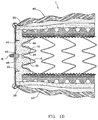
- FIG. 1 there is illustrated a cross-section of a mattress, indicated generally at 1, taken across the width of the mattress so that the view is along the length of the mattress.
- the following description is made with general reference to generally rectilinear mattresses having orthogonal side and end walls, regardless of the lengths of the walls as may vary among different conventional mattress from twin to king.
- the present invention pertains to mattress of all sizes.
- the internal construction of the mattress includes an innerspring assembly, indicated generally at 10, including a plurality of spring coils 11 (referred to herein simply as "coils”), each having a series of intermediate helical convolutions 12 and top and bottom terminal convolutions, 13 and 14 respectively, each of the convolutions having a common generally vertically oriented axis.
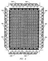
- the coils 11 may be arranged in the innerspring assembly in any manner, but are most commonly arranged in rows to fill substantially the entire area within the generally rectilinear perimeter of a mattress, as described for example in U.S. Patent 4,092,749, incorporated herein by reference, and shown in FIG. 8.
- the terminal convolutions 13 and 14 of each of the coils are commonly connected by cross-helical lacing wires 15 which are laced about the tangential terminal convolutions of the coil in adjacent rows, across the width of the innerspring assembly 10.
- An end cross-helical wire is also installed along the terminal convolutions of the coils in the end rows of the innerspring assembly.
- An internal mattress wall structure 20 is interlockingly engaged with each of the convolutions of all of the coils along the side walls, end walls and corners of the innerspring assembly to form a substantially continuous wall structure which surrounds or encompasses the innerspring assembly.
- the internal mattress wall structure 20 includes the structure which engages the longitudinal side walls of the innerspring assembly is referred to herein as the "internal mattress side wall structure 20A” or simply the “side wall structure”. And the structure which engages the end walls of the innerspring assembly is referred to herein as the "internal mattress end wall structure 20B" or simply the "end wall structure”.
- the internal mattress wall structure 20 includes a main body section 21, a generally planar side wall 22, a top surface 23 and bottom surface 24 which are each generally perpendicular to side wall 22 to form a top edge 25 and a bottom edge 26, parallel rows of flanges 27 attached to and extending laterally inward from a side of the main body section opposite side wall 22, each of the flanges 27 having an extension section 28 and a terminal section 29.
- the extension section 28 is essentially eliminated.
- the flanges 27 are specially configured for mechanical engagement with the perimetrical coils of the innerspring assembly by frictional fit between the terminal and intermediate convolutions of the perimetrical coils, as specifically shown in the fully engaged position in FIG. 1.
- the extension section 28 of each of the flanges is tapered to generally follow the helical angle between the convolutions of each of the coils, and the terminal section 29 has a generally rounded cross-section so that it is slightly compressed by adjacent convolutions, and to facilitate insertion of the flanges between the coil convolutions.
- the top and bottom surfaces 23 and 24 of the internal mattress side wall structure are overlapped by the terminal convolutions of the coils and thereby compressed toward the adjacent intermediate convolution to grip the entire cross-section of the wall structure 20 between each of the convolutions of the coils along the side of the innerspring assembly, from the top to the bottom of the innerspring assembly and coils.
- a substantial space is provided between each of the flanges 27, extension sections 28 and terminal sections 29 in order to achieve the close mechanical fit of the flanges between the coil convolutions.
- the top and bottom surfaces 23 and 24 each further include a ridge 30 which protrudes generally perpendicularly from the surface and approximately aligned with the terminal sections 29.
- the ridges 30 are positioned relative to terminal sections 29 to be overlapped by the terminal convolutions of the coils, thereby further contributing to the interlocking mechanical engagement of the internal mattress wall structure with the innerspring assembly.
- Ridge 30 of side wall structure 20A shown in FIG. 1 mechanically engages with the first few helical turns of lacing wires 15.
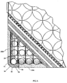
- Ridge 30 of end wall structure 20B shown in FIG. 3 is mechanically engaged against an internal side of lacing wires 15.
- the side wall 22 may include a slight concave or internal camber which is forced outward to a vertical plane by convergence of the flanges 27 as they are interlocked with the coil convolutions.
- the side wall 22 may be extended vertically beyond the top and bottom surfaces 23 and 24, to thereby extend beyond the terminal convolutions of the coils, to position extended top and bottom surfaces 25 and 26, and edges 25a and 26a, closer to the exterior (upholstered) edge of the mattress.
- the side wall 22 in this embodiment thus extends substantially over the entire surface area of the side walls of the finished mattress, to thereby create an even smoother flat finished appearance to the walls of the finished mattress, which greatly contributes to the consumer appeal of the mattress.
- top and bottom edges 25a and 26a are widened to provide greater horizontal surface area to the wall structures, which further improves support characteristics and facilitates padding and upholstery material attachment.
- the height or vertical extent of the wall structures 20 can be increased by stacking rows of extruded wall structures, as shown for example in FIG. 1C.
- An upper wall structure 20u may be simply stacked or interlockingly engaged with a lower wall structure 201 to increase the height of side wall 22 as measured from top surface 23 to bottom surface 24.
- the lower individual height profiles of structures 20u and 201 are also advantageous because they are somewhat simpler to manufacture by a foam extrusion process than structures having a larger cross-sectional profile.
- clearance for handle mounting fittings 49 is provided by notches 48 in the main body section 21 of the wall structure 20, to project through side wall 22 and the upholstery material thereover, at several points around the perimeter of the mattress for attachment of handles to the mattress material and/or upholstery. Notches 48 effectively conceal the presence of fittings 49 to provide for a smooth finished appearance to the upholstery about the handle H.
- each of the embodiments of the wall structures of the invention it is important to note that as a result of the foam material construction and the cross-sectional geometry of the interlockingly flanges, the wall structures have spring and support characteristics which are comparable and even superior to the support characteristics of the innerspring assembly, so that the sides and edges of a mattress constructed with the wall structures of the invention provide at least equal support as the innerspring area of the mattress, and improved support at the edges of mattresses of the prior art, including those relying principally upon a borderwire for edge support.
- each of the described structures can be made from extruded closed cell foam such as polyethylene which has excellent resilient properties for the described use.
- the extrusion process forms a tough outer skin to each of the structures which assists in the mechanical engagement of the structures with an innerspring assembly, i.e., the structures cannot be easily torn by the wire of the innerspring.
- the skin also allows the structures to hold the described shapes and configurations throughout the life of the mattress.
- the cross-sectional profile of the internal mattress end wall structure 20B, configured for engagement with the ends of the innerspring assembly, is slightly different from side wall structure 20A, in that the lowermost flange 27 is partially truncated to allow it to fit between the terminal convolution and the adjacent intermediate convolution which are at a different elevation than the convolutions facing the side of the assembly, and to allow overlapping of the ridge 30 on bottom surface 24 by the end helical wire which laces the terminal convolutions of the coils along the end of the innerspring assembly, to further enhance the mechanical engagement of the end wall structure 20B with the innerspring assembly.
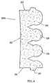
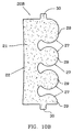
- FIGS. 10A and 10B Other cross-sectional profiles of the wall structures are within the scope of the invention, such as illustrated for example by FIGS. 10A and 10B, wherein the terminal sections 29 are slightly more circular, the flanges 27 minimized, and the gaps between the flanges slightly enlarged to provide increased adaptability of the structure for engagement with helical coils of various dimensions.
- the terminal sections 29 are slightly more circular, the flanges 27 minimized, and the gaps between the flanges slightly enlarged to provide increased adaptability of the structure for engagement with helical coils of various dimensions.
- ridges 30 are slightly elongated to increase the frictional gripping force with the overlying terminal convolutions and helical lacing wires.
- the wall and corner structures of the invention can be adapted to fit with any type of helical coil array so long as the flanges are dimensioned to fit between the coil convolutions.
- the main body section 21, wall surface 22 and/or top and bottom flanges 27 which engage between the terminal and intermediate coil convolutions can be over or undersized so that the overall height of the wall structure is equal to or greater than that of the perimetrical coils.
- the side and end wall structures are readily interlockingly engaged with an innerspring assembly by simply aligning the top and bottom edges 25 and 26 with the terminal convolutions of the perimetrical coils, whereat the flanges 27 are aligned with the gaps between the coil convolutions, and a striking force applied along the linear extent of the vertical wall 22 to urge the terminal sections 29 into engagement with the coil convolutions.
- the wall structures simply snap into engagement about the perimeter of the innerspring assembly, without the need for any special tools, fasteners, or assembly techniques.
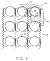
- the internal mattress wall structure 20 further includes corner pieces 30, configured to snap fit and lock about the corner coils of a rectangular innerspring assembly, and to abut the terminal ends of the side and end wall structures 20A and 20B to form a smooth corner wall to the internal mattress structure.
- the corner pieces of this embodiment have a main body section 31 with an external arcuate corner wall 32, intersecting interior walls 33, and a generally circular cavity 34 in the main body dimensioned to fit radially about the convolutions of the single coil at the corner of the innerspring assembly. As shown in FIG.
- the corner pieces may be formed as a single piece extrusion as further described below, with the arcuate angle of the corner less than ninety degrees, so that the interior walls 33 must be spread apart to install the piece about the coil, to thereby position the interior walls perpendicular and flush to the exterior wall of the abutting side and end wall structures, and to provide a mechanical gripping force of the corner piece upon the corner coil.
- corner pieces 30 may be alternately formed with vertically extended external arcuate corner walls 35 to form extended top and bottom arcuate surfaces 36 and 37 which are coplanar with extended top and bottom surfaces 25 and 26 of the corresponding embodiment of side wall structures 20.
- a notch 38 may be formed between the interior walls 33 and corner walls 35 to facilitate engagement with the corner coils and with the upper and lower terminal convolutions of the coils.
- the linear length of the side wall structures 20A and the end wall structures 20B can be selectively cut to closely match the length of the innerspring assembly sides and ends so that the combined structures engage all or substantially all of the perimetrical coils, with the abutting ends of the wall structures and the corner pieces forming a flush and continuous vertical wall surface 22 about the entire perimeter of the mattress.
- the wall and corner structures are critical to the integral and accurate attachment of the many layers of mattress padding and upholstery materials about the innerspring assembly and directly to the wall and corner structures.
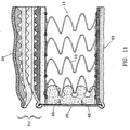
- multiple fabric and material layers 40 are laid over the terminal convolutions of the coils and extend to the mattress edges 25 and 26, as clearly defined by the wall structures 20A and 20B.
- an interior covering or liner 42 Prior to attachment of an exterior upholstery layer 43, an interior covering or liner 42 is pulled down over the edges 25 and 26, flush against vertical wall surface 22, and stapled directly through the wall surface 22 into main body section 21 by a plurality of fasteners 45, which may be for example flare staples or barbed tacks or helical pins or the like, which when inserted through wall surface 22, and through the skin layer of the structure formed in an extrusion manufacturing process, firmly engage the wall structures to tightly secure the lining and all of the layers of padding thereunder to the internal structure of the mattress.
- the broad area of the wall surface 22 allows the mattress assembler to optimally select the points of attachment of the liner 42 to locate the mattress exterior edge 46 substantially equidistant from the top and bottom edges 25 and 26 of the wall structures 20.
- the wall surface 22 thereby makes possible an upholstered tape edge 47 which is very straight and true, since it follows top and bottom edges 25 and 26, or 25a and 26a. The straight tape edge 47 also contributes greatly to the consumer appeal
- any padding and upholstery material layers used in mattress construction can be attached in various combinations to the mattress structures of the invention, including but not limited to wool laminate, polyurethane and/or high performance foam, cotton felt or batting, MT backing, pin convoluted foam SP3 fiber pad, or other suitable materials.
- FIG. 8 illustrates an alternate embodiment of the wall structures of the invention in which the flanges 27 are veritcally oriented and relatively spaced to fit between and mechanically engage the perimetrical coils.
- the extension and terminal sections of the flanges can be similarly configured as described above, and the main body section similarly provides the external wall surface 22 and the top and bottom edges 25 and 26.
- the corner piece 30 of this embodiment is simply a short section of the wall structure with two flanges spaced to surround and engage the corner coil and its two adjacent coils, to form the smooth arcuate corner wall 32.
- the structures 20 can be advantageously incorporated into a one-sided mattress, indicated generally at 50, having additional padding and upholstery materials attached to an upper surface 51, and a generally flat bottom surface 52.
- a substantial amount of additional padding and material is secured to the internal mattress structure in the same manner as described above with flare staples 45. Constructed with foam padding material and innersprings which do not take a set, only the upper surface 51 is used as the sleeping surface.
- the additional perimetric support provided by the wall structures 20 allows the one-sided mattress 50 to perform equivalently to a conventional mattress which is regularly flipped. Also, the elimination of padding and upholstery material from the bottom surface reduces the overall height of the mattress, and provides for a more stable fit upon a mattress foundation.
- any of the wall and corner structures of the invention can be formed by extrusion of thermoplastic extrudable foam materials such as polyethylene, polyethylene-based polymers, including EVA, ionomers and other co-polymers and are preferably made of extruded closed cell foam. Thickness, shape and contours of the structures can be selectively varied through extrusion die design and material selection. The thickness of the skin which forms about the structures in the extrusion process can be varied by extrusion rate. Materials and additives can be selected to provide any desired edge support characteristics and attributes such as firmness, density, compression, load deflection, fire retardancy or color. Also, the invention allows for the complete elimination of the relatively stiff borderwires of innerspring assemblies of the prior art, thus enabling a mattress constructed in accordance with the invention to be folded along a transverse axis, for example in half, to facilitate handling and shipment.
- thermoplastic extrudable foam materials such as polyethylene, polyethylene-based polymers, including EVA, ionomers and other co-polymers
- the invention thus provides improved internal mattress wall structures which are easily assembled with conventional innerspring assemblies by interlocking engagement without the need for any specialized assembly tools or fasteners.
- the smooth wall surface of the structures provides an optimal area for integral attachment of the interior padding layers, as well as the well-defined top and bottom edges, all of which improve the finished appearance of the upholstered edges of the mattress.
Landscapes
- Mattresses And Other Support Structures For Chairs And Beds (AREA)
- Springs (AREA)
Claims (22)
- Innerer Matratzenwandaufbau (20) für das formschlüssige Eingreifen in die Spulen (11) einer Matratzenfederkernanordnung (10), um als federnd elastischer innerer Aufbaubestandteil einer Matratze zu dienen, wobei der Wandaufbau aufweist:einen Hauptkörperabschnitt (21) mit einer im allgemeinen ebenen Wandfläche (22), die Wandfläche schneidenden oberen und Bodenflächen (23, 24), einer Vielzahl von parallelen Flanschen (27), die sich seitlich von dem Hauptkörperabschnitt (21) weg von der Wandfläche erstrecken und für das Einführen zwischen Windungen (12) von Umfangsspulen einer Federkernanordnung (10) bemessen sind, dadurch gekennzeichnet, daß jeder Flansch von benachbarten Flanschen im Abstand angeordnet ist und Anschlußabschnitte (29) hat mit einer Konfiguration für den innigen mechanischen Eingriff zwischen Windungen (12) von Umfangsspulen einer Federkernanordnung (10), wobei die ebene Wandfläche des Wandaufbaues an einem Umfang der Federkernanordnung positionierbar ist und sich mindestens von einer Oberseite der Federkernanordnung zu einem Boden der Federkernanordnung erstreckt, um als Bauwand einer Matratze zu dienen.
- Wandaufbau nach Anspruch 1, ferner mit einer Rippe, die sich von der oberen und Bodenfläche erhebt und an einer Stelle seitlich einwärts von der Wandfläche positioniert ist, wo Anschlußwindungen von Spulen, mit welchen der Wandaufbau in Eingriff steht, die Rippe auf der oberen und Bodenfläche überlappen.
- Wandaufbau nach Anspruch 1, wobei die Flansche verjüngt sind, um allgemein mit einem Spiralwinkel der Spulen der Federkernanordnung in Übereinstimmung zu kommen, bei welchen der Wandaufbau in Eingriff bringbar ist.
- Wandaufbau nach Anspruch 1, wobei eine Querschnittskonfiguration der Anschlußabschnitte der Flansche im allgemeinen kreisförmig ist.
- Wandaufbau nach Anspruch 1, wobei die Wandfläche innen gewölbt ist.
- Wandaufbau nach Anspruch 1, wobei mindestens einer der Flansche teilweise verkürzt ist.
- Wandaufbau nach Anspruch 1, der aus extrudiertem Schaum aufgebaut ist.
- Wandaufbau nach Anspruch 1, wobei eine vertikale Länge der Wandfläche mindestens gleich einem Höhenmaß der Spulen einer Federkernanordnung ist, mit welcher der Wandaufbau in Eingriff bringbar ist.
- Wandaufbau nach Anspruch 1, der um einen Umfang einer Matratzenfederkernanordnung in Eingriff ist.
- Wandaufbau nach Anspruch 1, der aus gegossenem Polymerschaum aufgebaut ist.
- Wandaufbau nach Anspruch 1 mit einer im allgemeinen linearen Erstreckung für den Eingriff mit einer geraden Seite oder Endwand einer Federkernanordnung.
- Wandaufbau nach Anspruch 1 in einer im allgemeinen gekrümmten äußeren Konfiguration und einem im allgemeinen zylindrischen inneren Hohlraum für die Anbringung um eine Eckenspule einer Federkernanordnung.
- Wandaufbau nach Anspruch 1 mit oberen und unteren Abschnitten, die relativ zu einer Matratzenfederkernanordnung angeordnet werden können, um eine kontinuierliche Seitenwand an einer Matratzenfederkernanordnung zu bilden.
- Wandaufbau nach Anspruch 1, der mechanisch mit einer Matratzenfederkernanordnung in Eingriff steht.
- Wandaufbau nach Anspruch 14, ferner mit Matratzenmaterial, welches an dem Wandaufbau angebracht ist.
- Wandaufbau nach Anspruch 1, der aus extrudiertem Schaum mit geschlossenen Zellen aufgebaut ist.
- Wandaufbau nach Anspruch 1, wobei eine vertikale Länge der Wandfläche größer ist als das Höhenmaß der Spulen einer Federkernanordnung, mit welcher der Wandaufbau in Eingriff bringbar ist.
- Matratze mit:einer Matratzenfederkernanordnung mit einer Vielzahl von miteinander verbundenen Spulen, die in im allgemeinen parallelen Reihen angeordnet sind, und Umfangsspulen zum Bilden einer im wesentlichen gradlinigen Federkernanordnung,einem inneren Matratzenwandaufbau mit einem Hauptkörperabschnitt mit einer ebenen Wandfläche, oberen und Bodenflächen, die im allgemeinen senkrecht zu der Wandfläche liegen, einer Rippe, die sich von der oberen und der Bodenwand erstreckt, und einer Vielzahl von parallelen Flanschen, die sich seitlich von dem Hauptkörperabschnitt gegenüber der Wandfläche erstrecken, wobei die Flansche im Abstand angeordnet sind und Anschlußabschnitte haben, die mit Umfangsspulen der Federkernanordnung mechanisch in Eingriff sind,einem inneren Matratzenwandaufbau in formschlüssigem Eingriff mit Windungen der Umfangsspulen der Matratzenfederkernanordnung durch Einbringen der Wandaufbauflansche und der Rippen zwischen Windungen der Umfangsspulen, wobei der Wandaufbau somit positioniert ist, so daß die ebene Wandfläche um einen Umfang der Federkernanordnung herum positioniert ist, um einen inneren Umfang der Matratze zu bilden, und sich mindestens von einer Oberseite der Federkernanordnung zu einem Boden der Federkernanordnung erstreckt, um innere obere und Bodenränder der Matratze zu bilden, undMatratzenfüll- und Polstermaterial, welches über der Federkernanordnung und dem inneren Matratzenwandaufbau liegt und direkt an dem inneren Matratzenwandaufbau angebracht ist.
- Matratze nach Anspruch 18, wobei der innere Matratzenwandaufbau eine Vielzahl linearer Abschnitte von Wandaufbauten mit anstoßenden, sich berührenden Enden aufweist, wobei die Wandaufbauten im wesentlichen einen Umfang der Federkernanordnung umgreifen.
- Matratze nach Anspruch 18, ferner mit einem Eckenaufbau mit einem Hauptkörperabschnitt mit einer bogenförmigen Wandfläche und einer Öffnung in dem Hauptkörperabschnitt zur Aufnahme einer Eckenspule, wobei der Eckenaufbau um eine Eckenspule in Eingriff ist.
- Matratze nach Anspruch 18, wobei das Matratzenfüll- und Polstermaterial an dem inneren Matratzenwandaufbau durch offene Klammern bzw. Aufweitungshefter durch das Material und in dem Hauptkörperabschnitt angebracht ist.
- Matratze nach Anspruch 18, wobei sie eine einseitige Matratze ist mit einer einzigen gepolsterten Schlaffläche und einer im allgemeinen flachen Bodenfläche.
Applications Claiming Priority (3)
| Application Number | Priority Date | Filing Date | Title |
|---|---|---|---|
| US08/726,028 US5787532A (en) | 1996-10-04 | 1996-10-04 | Internal mattress wall structures interlockingly engageable with mattress innerspring assemblies |
| US726028 | 1996-10-04 | ||
| PCT/US1997/017689 WO1998014097A1 (en) | 1996-10-04 | 1997-09-30 | Internal mattress wall structures interlockingly engageable with mattress innerspring assemblies |
Publications (3)
| Publication Number | Publication Date |
|---|---|
| EP1018911A1 EP1018911A1 (de) | 2000-07-19 |
| EP1018911A4 EP1018911A4 (de) | 2000-09-27 |
| EP1018911B1 true EP1018911B1 (de) | 2005-11-16 |
Family
ID=24916916
Family Applications (1)
| Application Number | Title | Priority Date | Filing Date |
|---|---|---|---|
| EP97945415A Expired - Lifetime EP1018911B1 (de) | 1996-10-04 | 1997-09-30 | Seitenwände für matratzen die formschlüssig in die federn eingreifen |
Country Status (13)
| Country | Link |
|---|---|
| US (1) | US5787532A (de) |
| EP (1) | EP1018911B1 (de) |
| JP (1) | JP4020168B2 (de) |
| KR (1) | KR100522338B1 (de) |
| AT (1) | ATE309725T1 (de) |
| AU (1) | AU735223B2 (de) |
| BR (1) | BR9712253A (de) |
| CA (1) | CA2267501C (de) |
| DE (1) | DE69734681T2 (de) |
| ES (1) | ES2249804T3 (de) |
| IL (1) | IL129128A (de) |
| NZ (1) | NZ334810A (de) |
| WO (1) | WO1998014097A1 (de) |
Families Citing this family (82)
| Publication number | Priority date | Publication date | Assignee | Title |
|---|---|---|---|---|
| US6149143A (en) * | 1995-03-20 | 2000-11-21 | L&P Property Management Company | Spring structure for a mattress innerspring having coaxial coil units |
| US6023803A (en) * | 1997-11-07 | 2000-02-15 | Ohio Mattress Company Licensing And Components Group | Mattress with high ILD firm topper |
| US5974609A (en) * | 1998-06-29 | 1999-11-02 | The Spring Air Company | Quilt top mattress with convoluted foam cushion |
| US6128798A (en) * | 1998-09-04 | 2000-10-10 | Sealy Technology Llc | Cavitated pad and innerspring assembly combination having springs with free terminal convolutions |
| ATE262821T1 (de) | 1998-12-11 | 2004-04-15 | Hill Rom Services Inc | Seitenpolstersystem für eine matratze |
| US6427264B1 (en) | 1999-03-19 | 2002-08-06 | Hill-Rom Services, Inc. | Gap filler for bed |
| ES2165277B1 (es) * | 1999-06-28 | 2003-10-01 | Colchones Java S A | Refuerzo periferico para colchones de muelles. |
| US6199234B1 (en) | 1999-07-28 | 2001-03-13 | Mark Srour | Infant comfort mattress |
| US6243900B1 (en) * | 2000-01-13 | 2001-06-12 | Simmons Company | One-sided mattress construction |
| US6263533B1 (en) * | 2000-06-02 | 2001-07-24 | Sealy Technology Llc | Extruded foam reinforcement structures for innerspring assemblies and mattresses |
| US6701557B2 (en) * | 2001-11-29 | 2004-03-09 | Sealy Technology Llc | Single piece foam toppers with perimeter areas having variable support and firmness properties |
| US6721982B2 (en) | 2002-03-25 | 2004-04-20 | Sealy Technology Llc | Quilt-stitched internal mattress pillows |
| US6568014B1 (en) | 2002-03-28 | 2003-05-27 | Serta, Inc. | Edge support on a mattress |
| KR100365241B1 (ko) * | 2002-07-11 | 2002-12-26 | 주식회사 에이스침대 | 매트리스 |
| US7082635B2 (en) * | 2003-03-28 | 2006-08-01 | Sealy Technology Llc | Unitized thermoplastic foam structures |
| US7185379B2 (en) * | 2003-03-28 | 2007-03-06 | Sealy Technology Llc | Foam encased innerspring with internal foam components (triple case) |
| US7870626B2 (en) * | 2003-05-29 | 2011-01-18 | Spring Air International Llc | Mattress having a spring unit with a single upper peripheral border rod locked within a chamber of a synthetic foam plastic material housing |
| US20110173757A1 (en) * | 2009-09-02 | 2011-07-21 | Denver Mattress Co. Llc | Cushioning devices and methods |
| US7284494B2 (en) * | 2003-11-10 | 2007-10-23 | Denver Mattress Co., Llc | High comfort mattresses having fiberballs |
| KR20050043593A (ko) * | 2004-04-16 | 2005-05-11 | 이헌수 | 매트리스의 스프링 조립체 |
| CA2565603C (en) * | 2004-05-27 | 2012-10-09 | Nomaco, Inc. | Foam welding and profile manufacturing system |
| NO20052205A (no) * | 2005-05-04 | 2006-03-27 | Porolon As | Madrass med integrert skumdel |
| US7386897B2 (en) * | 2005-06-09 | 2008-06-17 | L&P Property Management Company | Bedding or seating product made with coil springs having unknotted end turns |
| KR100743885B1 (ko) * | 2005-09-01 | 2007-07-30 | 주식회사 에이스침대 | 매트리스용 스프링구조체와 쿠션재의 고정장치 및 고정방법 |
| US8104122B2 (en) | 2005-12-19 | 2012-01-31 | Hill-Rom Services, Inc. | Patient support having an extendable foot section |
| US7287291B2 (en) * | 2006-01-23 | 2007-10-30 | Mattress Development Company | Mattress with improved edge support |
| EP1983865B1 (de) | 2006-02-08 | 2015-03-25 | Hill-Rom Services, Inc. | Endplatte für patientenauflagevorrichtung |
| WO2008088740A1 (en) * | 2007-01-18 | 2008-07-24 | Nomaco, Inc. | Method for manufacturing enhanced foam thermoplastic products |
| USD575145S1 (en) | 2007-02-09 | 2008-08-19 | L&P Property Management Company | Box spring corner piece |
| USD575144S1 (en) | 2007-02-09 | 2008-08-19 | L&P Property Management Company | Box spring corner piece |
| KR100859136B1 (ko) | 2007-02-15 | 2008-09-18 | 주식회사 에이스침대 | 쿠션시트를 이용한 침대매트리스 |
| US7845036B2 (en) * | 2007-07-09 | 2010-12-07 | Hickory Springs Manufacturing Company | Edge support for mattress assembly and method for making and using the same |
| US20090038072A1 (en) * | 2007-08-10 | 2009-02-12 | Defranks Michael S | Fire resistant corner guard |
| US7636971B2 (en) * | 2008-01-18 | 2009-12-29 | Sealy Technology Llc | Innerspring dampening inserts |
| US8230538B2 (en) * | 2008-01-18 | 2012-07-31 | Sealy Technology Llc | Mattress innerspring inserts and supports |
| US7805790B2 (en) * | 2008-01-18 | 2010-10-05 | Sealy Technology Llc | Foam springs and innerspring combinations for mattresses |
| US8266747B1 (en) | 2008-06-24 | 2012-09-18 | Nomaco Inc. | Mattress side/edge support system |
| DE202009005301U1 (de) * | 2009-04-06 | 2010-09-16 | Diemer & Dr. Jaspert GbR (vertretungsberechtigter Gesellschafter: Herrn Dr. Bodo F. Jaspert, 85630 Grasbrunn) | Federelement, insbesondere für eine Federkernmatratze |
| JP5222220B2 (ja) * | 2009-05-11 | 2013-06-26 | シモンズ株式会社 | マットレス |
| US8561236B2 (en) * | 2009-06-22 | 2013-10-22 | Nomaco Inc. | Stepped-edge and side-support members, assemblies, systems, and related methods, particularly for bedding and seating |
| US8646136B2 (en) * | 2009-08-27 | 2014-02-11 | Nomaco Inc. | Assemblies, systems, and related methods employing interlocking components to provide at least a portion of an encasement, particularly for bedding and seating applications |
| US8375493B2 (en) | 2009-08-27 | 2013-02-19 | Sealy Technology Llc | One piece foam mattress core encasement |
| US20110191962A1 (en) * | 2009-12-11 | 2011-08-11 | Spring Air International Llc | Mattress having a foam panel which interlocks a spring assembly and a quilted assembly |
| KR101141289B1 (ko) | 2010-01-26 | 2012-05-04 | 주식회사 금성침대 | 매트리스용 에지포머를 이용한 비대칭형 매트리스 |
| US20110179579A1 (en) * | 2010-01-27 | 2011-07-28 | Nomaco Inc. | Expandable edge-support members, assemblies, and related methods, suitable for bedding and seating applications and innersprings |
| KR100970910B1 (ko) | 2010-03-19 | 2010-07-20 | (주)금성토탈퍼니처 | 침대 매트리스용 스프링조립체의 가요성 보강 구조 |
| KR101054446B1 (ko) | 2010-03-19 | 2011-08-04 | (주)금성토탈퍼니처 | 매트리스용 스프링 조립체 보강 구조 |
| USD677097S1 (en) | 2010-05-06 | 2013-03-05 | Nomaco, Inc. | Slotted side support |
| US8813286B2 (en) * | 2010-06-10 | 2014-08-26 | Indratech Llc | Tunable spring mattress and method of making same |
| US9392877B2 (en) | 2010-06-10 | 2016-07-19 | Indratech Llc | Tunable spring mattress and method of making same |
| US8490232B2 (en) * | 2010-06-23 | 2013-07-23 | L&P Property Management Company | Spring core having border wire with generally rectangular cross-section |
| US8769748B2 (en) | 2010-06-23 | 2014-07-08 | L&P Property Management Company | Spring core having border wire with generally rectangular cross-section |
| USD675856S1 (en) * | 2010-07-02 | 2013-02-12 | Nomaco Inc. | Foam support with coil enclosures for use in a mattress or a cushion |
| USD692689S1 (en) | 2010-08-17 | 2013-11-05 | Nomaco Inc. | Side support |
| USD694042S1 (en) | 2010-08-17 | 2013-11-26 | Nomaco Inc. | Side support |
| USD695550S1 (en) | 2010-08-17 | 2013-12-17 | Nomaca Inc. | Side support |
| USD694554S1 (en) | 2010-08-17 | 2013-12-03 | Nomaco Inc. | Side support |
| US8341778B2 (en) | 2011-02-07 | 2013-01-01 | Hill-Rom Services, Inc. | Bed gap filler and footboard pad |
| KR101054456B1 (ko) | 2011-03-09 | 2011-08-04 | (주)금성토탈퍼니처 | 침대용 매트리스의 회전 스프링 보강재 |
| WO2012155132A1 (en) * | 2011-05-12 | 2012-11-15 | Sealy Technology, Llc | Tension relief foam and mattress constructions |
| US20120304392A1 (en) * | 2011-05-31 | 2012-12-06 | Khambete Surendra S | Mattress system |
| CA2783982A1 (en) * | 2011-07-29 | 2013-01-29 | Dreamwell, Ltd. | Mattress assembly with high airflow |
| USD673801S1 (en) | 2011-08-03 | 2013-01-08 | Nomaco Inc. | Mattress bed encasement |
| USD673800S1 (en) | 2011-08-03 | 2013-01-08 | Nomaco Inc. | Mattress bed encasement |
| USD675051S1 (en) | 2011-09-30 | 2013-01-29 | Nomaco Inc. | Edge support cushion |
| CA2812477C (en) * | 2012-04-18 | 2016-02-02 | Otis Bed Manufacturing Company, Inc. | Linked coil mattress assembly |
| KR101427107B1 (ko) | 2013-01-04 | 2014-08-07 | 주식회사 에이스침대 | 완충기능을 갖는 침대용 파운데이션 |
| KR101428611B1 (ko) * | 2013-02-08 | 2014-08-08 | 현대자동차주식회사 | 재활용을 위한 자동차의 램프류 분리장치 |
| KR101304645B1 (ko) * | 2013-02-28 | 2013-09-05 | (주)한성헬스피아 | 매트리스 |
| USD740053S1 (en) | 2013-07-03 | 2015-10-06 | Nomaco Inc. | Foam cushion base |
| USD737074S1 (en) | 2013-07-03 | 2015-08-25 | Nomaco Inc. | Foam cushion base |
| KR101603949B1 (ko) | 2014-01-24 | 2016-03-25 | 가야폴리우레탄(주) | 하이브리드 쿠션 어셈블리 및 이의 제조방법 |
| US11076705B2 (en) | 2014-05-30 | 2021-08-03 | Sealy Technology, Llc | Spring core with integrated cushioning layer |
| WO2017023640A1 (en) * | 2015-08-03 | 2017-02-09 | Bedgear, Llc | Customizable mattress |
| US11033114B2 (en) | 2015-12-17 | 2021-06-15 | Sealy Technology, Llc | Coil-in-coil spring with variable loading response and mattresses including the same |
| CN108697242B (zh) | 2016-01-21 | 2021-08-20 | 丝涟科技有限责任公司 | 具有非线性负载响应的线圈套线圈弹簧和包括它的垫子 |
| SG11201901680TA (en) * | 2016-08-29 | 2019-03-28 | Madad Pty Ltd | Mattress |
| EP3703537B1 (de) | 2017-10-31 | 2024-06-26 | Sealy Technology, LLC | Taschenspiralfederanordnung mit flexiblem schaumstoff |
| US11013340B2 (en) | 2018-05-23 | 2021-05-25 | L&P Property Management Company | Pocketed spring assembly having dimensionally stabilizing substrate |
| US12369722B2 (en) | 2018-05-23 | 2025-07-29 | L&P Property Management Company | Method of disassembling pocketed spring assembly with dimensionally stabilizing substrate |
| EP3854266A4 (de) * | 2018-09-21 | 2021-11-10 | Fernandes, Francisco Rozendo | Strukturanordnung für eine matratze |
| JP7795791B2 (ja) * | 2023-03-08 | 2026-01-08 | 株式会社ルービックJp | クッション体 |
Family Cites Families (20)
| Publication number | Priority date | Publication date | Assignee | Title |
|---|---|---|---|---|
| US1865043A (en) * | 1928-05-17 | 1932-06-28 | Rome Company Inc | Spring filled mattress |
| FR780450A (fr) * | 1934-10-30 | 1935-04-26 | Dutilleul Et Lefebvre | Perfectionnements aux sommiers élastiques pour sièges et matelas |
| US2826769A (en) * | 1956-01-31 | 1958-03-18 | Eclipse Sleep Products Inc | Border stabilizer |
| US2940089A (en) * | 1956-12-24 | 1960-06-14 | Englander Co Inc | Mattress structure |
| US3173159A (en) * | 1962-04-03 | 1965-03-16 | Sealy | Cushion construction |
| US3262135A (en) * | 1964-05-13 | 1966-07-26 | Acd Bedding Corp | Bedding structure |
| US3618146A (en) * | 1969-04-24 | 1971-11-09 | Us Bedding Co The | Border stabilizer |
| GB1383615A (en) * | 1972-08-09 | 1974-02-12 | France Bed Co | Mattress |
| US3822426A (en) * | 1972-11-03 | 1974-07-09 | Sealy | Mattress topper pad and border stabilizer |
| US4067076A (en) * | 1976-08-17 | 1978-01-10 | Mirabed Ag | Upholstered body |
| US4677701A (en) * | 1985-11-19 | 1987-07-07 | Galumbeck Michael H | Firmness control device |
| US4726572A (en) | 1986-05-16 | 1988-02-23 | Sealy, Incorporated | Spring coil and spring assembly |
| DE3728148A1 (de) * | 1987-08-24 | 1989-03-09 | Andreas Breckle | Taschenfederkernmatratze |
| US5048167A (en) * | 1989-03-13 | 1991-09-17 | Heffley James R | Method for restoring used mattresses |
| US5133116A (en) * | 1990-12-21 | 1992-07-28 | The Ohio Mattress Company Licensing And Components Group | Method of stabilizing and reinforcing a spring border |
| US5113539A (en) * | 1991-07-31 | 1992-05-19 | Strell Brian M | Adjustable firmness coil spring mattress with inflatable tubes |
| US5239715A (en) * | 1992-02-11 | 1993-08-31 | The Ohio Mattress Company Licensing And Components Group | Border stabilizing and reinforcing member for use in mattresses, cushions and the like |
| US5467488A (en) * | 1992-02-11 | 1995-11-21 | The Ohio Mattress Co. Licensing & Components Group | Border stabilizing member and method for making mattresses, cushions and the like using the same |
| US5210890A (en) * | 1992-09-21 | 1993-05-18 | Tualatin Sleep Products | Mattress foundation with springs and foam elements |
| US5537699A (en) * | 1995-05-22 | 1996-07-23 | Foamex L.P. | Mattress border assembly and method of making same |
-
1996
- 1996-10-04 US US08/726,028 patent/US5787532A/en not_active Expired - Lifetime
-
1997
- 1997-09-30 JP JP51683498A patent/JP4020168B2/ja not_active Expired - Fee Related
- 1997-09-30 KR KR10-1999-7002946A patent/KR100522338B1/ko not_active Expired - Fee Related
- 1997-09-30 BR BR9712253-0A patent/BR9712253A/pt not_active Application Discontinuation
- 1997-09-30 AU AU46625/97A patent/AU735223B2/en not_active Ceased
- 1997-09-30 CA CA002267501A patent/CA2267501C/en not_active Expired - Fee Related
- 1997-09-30 WO PCT/US1997/017689 patent/WO1998014097A1/en not_active Ceased
- 1997-09-30 AT AT97945415T patent/ATE309725T1/de not_active IP Right Cessation
- 1997-09-30 DE DE69734681T patent/DE69734681T2/de not_active Expired - Lifetime
- 1997-09-30 ES ES97945415T patent/ES2249804T3/es not_active Expired - Lifetime
- 1997-09-30 IL IL12912897A patent/IL129128A/en not_active IP Right Cessation
- 1997-09-30 EP EP97945415A patent/EP1018911B1/de not_active Expired - Lifetime
- 1997-09-30 NZ NZ334810A patent/NZ334810A/xx not_active IP Right Cessation
Also Published As
| Publication number | Publication date |
|---|---|
| CA2267501C (en) | 2005-12-13 |
| BR9712253A (pt) | 2000-01-25 |
| JP2001507583A (ja) | 2001-06-12 |
| IL129128A0 (en) | 2000-02-17 |
| KR100522338B1 (ko) | 2005-10-19 |
| IL129128A (en) | 2001-09-13 |
| DE69734681T2 (de) | 2006-09-28 |
| AU735223B2 (en) | 2001-07-05 |
| AU4662597A (en) | 1998-04-24 |
| WO1998014097A1 (en) | 1998-04-09 |
| NZ334810A (en) | 2000-10-27 |
| ATE309725T1 (de) | 2005-12-15 |
| DE69734681D1 (de) | 2005-12-22 |
| EP1018911A4 (de) | 2000-09-27 |
| ES2249804T3 (es) | 2006-04-01 |
| JP4020168B2 (ja) | 2007-12-12 |
| HK1029262A1 (en) | 2001-03-30 |
| CA2267501A1 (en) | 1998-04-09 |
| US5787532A (en) | 1998-08-04 |
| KR20000048915A (ko) | 2000-07-25 |
| EP1018911A1 (de) | 2000-07-19 |
Similar Documents
| Publication | Publication Date | Title |
|---|---|---|
| US5787532A (en) | Internal mattress wall structures interlockingly engageable with mattress innerspring assemblies | |
| CN1321605C (zh) | 内簧组装件和垫子的挤压泡沫增强结构 | |
| US6651276B2 (en) | Floating slat frame for a mattress foundation | |
| US5687439A (en) | Border stabilizing member and innerspring assembly using same | |
| US7424763B2 (en) | Channel-cut cushion supports | |
| US11793320B2 (en) | Low density pocket spring mattress with integrated cushioning pads | |
| AU2001249949A1 (en) | Extruded foam reinforcement structures for innerspring assemblies and mattresses | |
| US11103084B2 (en) | Comfort layer having spacer pocketed springs | |
| AU2003220561A1 (en) | Improved edge support on a mattress | |
| US20200288873A1 (en) | Comfort Layer Having Pocketed Springs of Different Heights | |
| US20080295251A1 (en) | Mattress Having Foam Encasement and Method of Making the Same | |
| US8955182B1 (en) | Perimeter-wrapped mattress and method of manufacture | |
| US20020069463A1 (en) | Stackable bedding foundation | |
| HK1029262B (en) | Internal mattress wall structures interlockingly engageable with mattress innerspring assemblies | |
| EP1039819B1 (de) | Federkernmatratze | |
| MXPA99002926A (es) | Estructuras de pared interna de colchon entrelazadamente embragadas con el montaje de resortes internos del colchon | |
| IL153158A (en) | New use of type 1 angiotensin II antagonists in the manufacture of a drug for the prophylactic and / or therapeutic treatment of vascular headaches that are not caused by hypertension |
Legal Events
| Date | Code | Title | Description |
|---|---|---|---|
| PUAI | Public reference made under article 153(3) epc to a published international application that has entered the european phase |
Free format text: ORIGINAL CODE: 0009012 |
|
| 17P | Request for examination filed |
Effective date: 19990415 |
|
| AK | Designated contracting states |
Kind code of ref document: A1 Designated state(s): AT CH DE ES GB LI PT |
|
| A4 | Supplementary search report drawn up and despatched |
Effective date: 20000816 |
|
| AK | Designated contracting states |
Kind code of ref document: A4 Designated state(s): AT CH DE ES GB LI PT |
|
| RIC1 | Information provided on ipc code assigned before grant |
Free format text: 7A 47C 23/04 A, 7A 47C 27/06 B |
|
| GRAP | Despatch of communication of intention to grant a patent |
Free format text: ORIGINAL CODE: EPIDOSNIGR1 |
|
| GRAS | Grant fee paid |
Free format text: ORIGINAL CODE: EPIDOSNIGR3 |
|
| RAP1 | Party data changed (applicant data changed or rights of an application transferred) |
Owner name: SEALY TECHNOLOGY LLC |
|
| GRAA | (expected) grant |
Free format text: ORIGINAL CODE: 0009210 |
|
| AK | Designated contracting states |
Kind code of ref document: B1 Designated state(s): AT CH DE ES GB LI PT |
|
| REG | Reference to a national code |
Ref country code: GB Ref legal event code: FG4D |
|
| REG | Reference to a national code |
Ref country code: CH Ref legal event code: NV Representative=s name: MICHELI & CIE INGENIEURS-CONSEILS Ref country code: CH Ref legal event code: EP |
|
| REF | Corresponds to: |
Ref document number: 69734681 Country of ref document: DE Date of ref document: 20051222 Kind code of ref document: P |
|
| REG | Reference to a national code |
Ref country code: ES Ref legal event code: FG2A Ref document number: 2249804 Country of ref document: ES Kind code of ref document: T3 |
|
| REG | Reference to a national code |
Ref country code: HK Ref legal event code: GR Ref document number: 1029262 Country of ref document: HK |
|
| PLBE | No opposition filed within time limit |
Free format text: ORIGINAL CODE: 0009261 |
|
| STAA | Information on the status of an ep patent application or granted ep patent |
Free format text: STATUS: NO OPPOSITION FILED WITHIN TIME LIMIT |
|
| 26N | No opposition filed |
Effective date: 20060817 |
|
| PGFP | Annual fee paid to national office [announced via postgrant information from national office to epo] |
Ref country code: CH Payment date: 20070809 Year of fee payment: 11 Ref country code: AT Payment date: 20070914 Year of fee payment: 11 |
|
| REG | Reference to a national code |
Ref country code: CH Ref legal event code: PL |
|
| PG25 | Lapsed in a contracting state [announced via postgrant information from national office to epo] |
Ref country code: AT Free format text: LAPSE BECAUSE OF NON-PAYMENT OF DUE FEES Effective date: 20080930 |
|
| PG25 | Lapsed in a contracting state [announced via postgrant information from national office to epo] |
Ref country code: LI Free format text: LAPSE BECAUSE OF NON-PAYMENT OF DUE FEES Effective date: 20080930 Ref country code: CH Free format text: LAPSE BECAUSE OF NON-PAYMENT OF DUE FEES Effective date: 20080930 |
|
| PGFP | Annual fee paid to national office [announced via postgrant information from national office to epo] |
Ref country code: ES Payment date: 20100831 Year of fee payment: 14 |
|
| PGFP | Annual fee paid to national office [announced via postgrant information from national office to epo] |
Ref country code: PT Payment date: 20100809 Year of fee payment: 14 |
|
| PGFP | Annual fee paid to national office [announced via postgrant information from national office to epo] |
Ref country code: DE Payment date: 20101126 Year of fee payment: 14 |
|
| REG | Reference to a national code |
Ref country code: PT Ref legal event code: MM4A Free format text: LAPSE DUE TO NON-PAYMENT OF FEES Effective date: 20120402 |
|
| REG | Reference to a national code |
Ref country code: DE Ref legal event code: R119 Ref document number: 69734681 Country of ref document: DE Effective date: 20120403 |
|
| PG25 | Lapsed in a contracting state [announced via postgrant information from national office to epo] |
Ref country code: DE Free format text: LAPSE BECAUSE OF NON-PAYMENT OF DUE FEES Effective date: 20120403 |
|
| PG25 | Lapsed in a contracting state [announced via postgrant information from national office to epo] |
Ref country code: PT Free format text: LAPSE BECAUSE OF NON-PAYMENT OF DUE FEES Effective date: 20120402 |
|
| PGFP | Annual fee paid to national office [announced via postgrant information from national office to epo] |
Ref country code: GB Payment date: 20120917 Year of fee payment: 16 |
|
| REG | Reference to a national code |
Ref country code: ES Ref legal event code: FD2A Effective date: 20130417 |
|
| PG25 | Lapsed in a contracting state [announced via postgrant information from national office to epo] |
Ref country code: ES Free format text: LAPSE BECAUSE OF NON-PAYMENT OF DUE FEES Effective date: 20111001 |
|
| GBPC | Gb: european patent ceased through non-payment of renewal fee |
Effective date: 20130930 |
|
| PG25 | Lapsed in a contracting state [announced via postgrant information from national office to epo] |
Ref country code: GB Free format text: LAPSE BECAUSE OF NON-PAYMENT OF DUE FEES Effective date: 20130930 |