EP1018917B1 - Safety device for household electric cooking appliance, such as a food processor, and appliance comprising said device - Google Patents
Safety device for household electric cooking appliance, such as a food processor, and appliance comprising said device Download PDFInfo
- Publication number
- EP1018917B1 EP1018917B1 EP98947594A EP98947594A EP1018917B1 EP 1018917 B1 EP1018917 B1 EP 1018917B1 EP 98947594 A EP98947594 A EP 98947594A EP 98947594 A EP98947594 A EP 98947594A EP 1018917 B1 EP1018917 B1 EP 1018917B1
- Authority
- EP
- European Patent Office
- Prior art keywords
- lid
- safety device
- cover
- detector
- receptacle
- Prior art date
- Legal status (The legal status is an assumption and is not a legal conclusion. Google has not performed a legal analysis and makes no representation as to the accuracy of the status listed.)
- Expired - Lifetime
Links
- 235000013305 food Nutrition 0.000 title claims description 14
- 238000010411 cooking Methods 0.000 title 1
- 230000002093 peripheral effect Effects 0.000 claims description 5
- 230000001012 protector Effects 0.000 claims 1
- 238000002360 preparation method Methods 0.000 description 15
- 238000001514 detection method Methods 0.000 description 13
- 235000021478 household food Nutrition 0.000 description 6
- 230000005540 biological transmission Effects 0.000 description 4
- 238000003825 pressing Methods 0.000 description 4
- 230000009471 action Effects 0.000 description 3
- 230000003213 activating effect Effects 0.000 description 3
- 230000008901 benefit Effects 0.000 description 3
- 230000004913 activation Effects 0.000 description 2
- 210000003323 beak Anatomy 0.000 description 2
- 239000004615 ingredient Substances 0.000 description 2
- 230000001681 protective effect Effects 0.000 description 2
- 208000031968 Cadaver Diseases 0.000 description 1
- 229910000746 Structural steel Inorganic materials 0.000 description 1
- 238000004140 cleaning Methods 0.000 description 1
- 238000010276 construction Methods 0.000 description 1
- 230000008034 disappearance Effects 0.000 description 1
- 238000006073 displacement reaction Methods 0.000 description 1
- 239000007788 liquid Substances 0.000 description 1
- 238000004519 manufacturing process Methods 0.000 description 1
- 230000004048 modification Effects 0.000 description 1
- 238000012986 modification Methods 0.000 description 1
- NJPPVKZQTLUDBO-UHFFFAOYSA-N novaluron Chemical compound C1=C(Cl)C(OC(F)(F)C(OC(F)(F)F)F)=CC=C1NC(=O)NC(=O)C1=C(F)C=CC=C1F NJPPVKZQTLUDBO-UHFFFAOYSA-N 0.000 description 1
- 210000000056 organ Anatomy 0.000 description 1
- 230000001846 repelling effect Effects 0.000 description 1
- 235000013311 vegetables Nutrition 0.000 description 1
Images






Classifications
-
- A—HUMAN NECESSITIES
- A47—FURNITURE; DOMESTIC ARTICLES OR APPLIANCES; COFFEE MILLS; SPICE MILLS; SUCTION CLEANERS IN GENERAL
- A47J—KITCHEN EQUIPMENT; COFFEE MILLS; SPICE MILLS; APPARATUS FOR MAKING BEVERAGES
- A47J43/00—Implements for preparing or holding food, not provided for in other groups of this subclass
- A47J43/04—Machines for domestic use not covered elsewhere, e.g. for grinding, mixing, stirring, kneading, emulsifying, whipping or beating foodstuffs, e.g. power-driven
- A47J43/07—Parts or details, e.g. mixing tools, whipping tools
- A47J43/075—Safety devices
- A47J43/0761—Safety devices for machines with tools driven from the lower side
- A47J43/0772—Safety devices for machines with tools driven from the lower side activated by the proper positioning of the cover
Definitions
- the present invention relates to a household appliance for preparation food processor, of the food processor type, comprising a body comprising a block motor, a working container designed to receive a rotary working member driven by the engine block, as well as a cover that can be placed on the working container in a simple movement to lock of the device.
- household food preparation appliance such as a food processor, means an apparatus intended for making chopped preparations, mixes, or grated or minced preparations.
- the document FR 2 447 703 describes a household appliance for preparation culinary, comprising a lid capable of being locked on a container working by means of a bayonet fixing system.
- Lid includes a tab directed downward and extended by a tongue directed outwards. When the lid is locked on the working container, this tab is located at a certain height from the bottom of said container.
- the body of the device has a side housing projecting from a base provided to receive the container.
- the housing has a slot parallel to the upper surface of the base, extending from one of the sides of the housing up to the face arranged opposite the base.
- the tongue engaged in the slot of the housing by rotation of the cover relative to the container actuates a safety device authorizing the operation of the device when said tongue is correctly positioned. This provision prevents the user removes the cover and accesses the work tools while these are operating in the working container.
- This embodiment has the drawback of requiring positioning precise cover with respect to the working container to lock the cover on the working container.
- the safety device requires that the cover is brought into a determined position relative to the housing for authorize the device to operate.
- the cover includes a chimney intended to introduce ingredients into the working container, the position thereof is determined by the position of the cover allowing the operation of the device. The user cannot choose the position of the lid.
- the document EP 0 549 818 describes a household appliance for preparation culinary including a working container locked on a body by means a bayonet fixing system, a lid locked on the container working by means of a bayonet fixing system, the cover comprising a tongue engaging in a slot of a housing forming a prominent part of the body for actuating a safety device authorizing the operation of the device.
- Such an embodiment allows the working container to be held on the body during operation of the device and avoids mechanically stressing the tongue actuating the safety device, but has the drawback of ask the user for two locking movements, each associating a precise positioning of the container relative to the body, or of the lid by relative to the container, followed by a rotation of the container relative to the body, or of the cover relative to the container.
- the document FR 2 340 706 describes a household appliance for preparation culinary comprising a base, the upper part of which constitutes a seat for receiving a removable accessory, such as a vegetable cutter, said accessory comprising a housing forming a working container and a cover covering the housing.
- the cover is locked with two diametrically locked locks opposite, of the so-called toggle type, each comprising a hook whose beak engages an ear on the base and which is hinged to the cover by by means of a tilting stirrup interposed between a boss on this cover and the end of this hook opposite its beak.
- the motor is controlled by a switch whose operating button is located on the upper part of the base and is actuated by means of a pusher mounted movably on the hook locking, via a transmission mounted in the housing the accessory.
- This construction has the disadvantage of providing an apparatus comprising a working container comprising transmission means used to start the appliance motor. The cleaning of said container is not facilitated by this provision. In addition, precise positioning of the cover, working container and the base of the appliance is necessary to carry out the locking the cover on the base.
- the document FR 2 370 456 describes a household mixer comprising a working container placed on a base and closed by a lid, the locking of the cover being ensured by a pivoting actuating lever around a horizontal axis and applied by a mobile bearing against a lever lock, which pivots around a fixed bearing and bears against the lid.
- the fixed bearing can move freely from a determined distance in the axial direction.
- a control rod guides a switch to a circuit actuation button controlling the motor of the device.
- Such an embodiment offers the advantage of proposing a device equipped with a security device authorizing the operation of said device only when the cover is correctly locked on the working container, and in which the cover can be placed without precise orientation on the working container, the working container can also be arranged without precise orientation on the base.
- this achievement the disadvantage of controlling locking as well as safety by rotation of a lever around a horizontal axis, which presents a risk of unbalance the device during locking or unlocking operations, if the device is not sufficiently maintained when operating the lever.
- Document DE 3,540,370 discloses a safety device for an appliance.
- household food preparation appliance of the household robot type comprising a body forming a base intended to receive a working container in which is likely to be arranged a rotary working member driven by a motor arranged in the body.
- a lid is provided to close the container of work.
- the parts opposite the cover and the working container have an axis of symmetry.
- the cover can be placed on the working container in an axial movement.
- the security system includes in the cover a detection element intended to cooperate with means for detecting the presence of the lid on the receptacle placed on the base, said detection means being arranged in the body.
- the cover can be inserted and removed using only axial movement.
- the aforementioned safety device requires positioning of the cover on the working container in a particular orientation.
- Document EP 0 076 712 discloses a household appliance of food preparation, of the food processor type, comprising a body forming a base designed to receive a working container in which is susceptible to be arranged a rotary working member driven by a motor arranged in the body.
- a cover is provided to close the working container. of the lid locking means close the working container arranged on pedestal.
- the parts opposite the cover and the working container have an axis of symmetry. The cover can be placed on the working container in an axial movement.
- the device's safety device is activated by the rotation of the crown locking the lid on the working container. Many movements are therefore necessary to close the cover and allow the switching on the appliance.
- the object of the invention therefore aims to remedy the various disadvantages listed above and to provide a safety device for a household food preparation appliance whose implementation work is particularly safe and easy.
- Another object of the present invention is to propose a security device for a kitchen appliance that offers a certain freedom to position the working container relative to the base the device.
- Another object of the present invention is to propose a security device for a kitchen appliance that offers a certain freedom of positioning of the cover relative to the working container.
- Another object of the present invention is to propose a security device for a kitchen appliance that is of inexpensive and reliable over time.
- Another object of the present invention is to propose an apparatus kitchen appliance with such a safety device.
- This arrangement allows a certain freedom of positioning of the cover on the working container.
- the user can for example choose between different positions for an ingredient introduction chimney arranged on the cover.
- the cover includes a detection ring provided for cooperate with at least one detector arranged in the body.
- the user thus has greater freedom of positioning of the lid on the container.
- the device comprises means magnetic, arranged on the periphery of the cover, said means being likely to cooperate with a magnetic detector, placed in the body and connected to detection electronics, when the cover is put in place on the container placed on the base.
- the device comprises a means of control mounted in the body and capable of being actuated by the cover placed on the container placed on the base, as well as a means of protection provided to come between the body and the container during actuation of the control means.
- the device comprises at least two control sensors arranged in the body, and capable of operating at at least one microswitch, said sensors each comprising at least one head likely to occupy an extended position in which the microswitch does not authorize the operation of the device, said heads being susceptible to be moved by the cover placed on the container placed on the base towards a retracted position in which the microswitch allows the operation of the device.
- the safety device according to the invention is intended to be used on a household food preparation appliance, such as a food processor.
- such an apparatus comprises a body 1 forming a base 2 intended to receive a working container 3 of axis of symmetry x-x 'in which a working member can be placed rotary 4 driven by a motor (not shown in said figures) arranged in the body 1, a cover 5 provided for closing the working container 3, and locking means (not shown in said figures) of the cover 5 on the working container 3 placed on the base 2.
- the working container 3 advantageously comprises a peripheral skirt lower 13 provided to cooperate with a flange 9 formed in the base 2.
- the working container 3 has side walls 28 and a bottom 29 in which is provided a central chimney 20 provided for the passage of means for driving the working member 4.
- the working member work 4 consists of a hub 21 on which is mounted in a known manner a working tool 22, as shown in Figures 1 to 2c. Hub 21 cooperates with a rod 19 mounted in the cover 5 to stabilize the rotation of the working organ 4.
- the motor (not shown in the figures) arranged in the body 1 of the device drives a transmission axis 23, mounted opposite an orifice 24 formed in the base 2, and on which is mounted the working member 4, as shown in Figure 1.
- the security device comprises means for detecting the presence of the cover 5 on the container 3 placed on the base 2.
- the security device is capable of being activated by the simple fitting of the cover 5 on the container 3 placed on the base 2.
- the security device authorizes the operation of the engine of the device driving the working member 4.
- the simple expression fitting the cover 5 placed on the container 3 you should hear a positioning of the cover using a movement simple of the user, with the exception of any movement involving at least two separate actions of the user, for example placing the cover 5 on the container 3, then turn the cover 5 relative to container 3.
- the cover 5 includes a detection ring intended to cooperate with at least one detector arranged in the body 1.
- the device comprises means controlling the braking of the motor when the cover 5 is removed from the container 3 placed on the base 2.
- the braking means can be controlled for example by the disappearance of the activation of the device.
- the safety device comprises magnetic means 300, disposed on the periphery of the cover 5, said means being capable of cooperate with a magnetic detector 301 placed in the body 1 and connected to detection electronics 302, when the cover 5 is placed on the container 3 placed on the base 2.
- the magnetic means 300 can consist for example of an annular magnetic strip or alternatively of a plurality of magnetic elements arranged on the cover 5 so that at least one element is detected by the detector 301 when the cover 5 is placed on the container 3 placed on the base 2.
- the detection ring is formed by the magnetic means 300 arranged on the cover 5 and the detector arranged in the body 1 is formed by the magnetic detector 301, which is connected to the detection electronics 302.
- the safety device is activated when the cover 5 is correctly fitted in place on the container 3 placed on the base 2.
- the magnetic detector 301 detects the presence of magnetic means 300 and authorizes the operation of the device via electronic circuit 302.
- the security device comprises a control means 320 mounted in the body 1 and capable of being actuated by the cover 5 placed on the container 3 disposed on the base 2, thus that a protective means 321 provided for interposing between the body 1 and the container 3 upon actuation of the control means 320, so that prevent actuation of the control means 320 by means other than the cover 5.
- a control means 320 mounted in the body 1 and capable of being actuated by the cover 5 placed on the container 3 disposed on the base 2, thus that a protective means 321 provided for interposing between the body 1 and the container 3 upon actuation of the control means 320, so that prevent actuation of the control means 320 by means other than the cover 5.
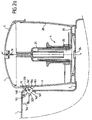
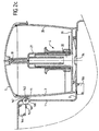
- the safety device comprises a rod 160 mounted in the body 1 pivoting on an axis 161 substantially perpendicular to the axis of revolution x-x 'of the container 3, against a return means (not shown in the figures) between a waiting position shown in Figure 2a and an active position shown in FIG. 2c.
- Rod 160 has a flat 162 provided to cooperate with a flange 11 of the cover 5, advantageously through an opening 168 formed in the body 1, said flat forming the control means 320.
- the rod 160 also includes a tab 163 provided for actuating a microswitch 164 when the cover 5 is placed on the container 3 disposed on the base 2.
- the flange 11 is in the form of a collar.
- the return means is provided to return the rod 160 to a standby position shown in Figure 2a in which the flange 11 of the cover 3 is likely to activate the flat 162.
- This provision of security means has the advantage of being independent of the locking means of the cover 5 on the working container 3 placed on the base 2.
- the rod 160 has a convex surface 167, advantageously cylindrical, which extends outside the body 1 when the tab 163 actuates the microswitch 164. This arrangement makes it difficult to actuate the rod 160 by a means other than the rim 11 of the cover 5.
- the surface 167 forms a means of protection 321 interposed between the body 1 and the container 3 during actuation of the flat 162 forming the control means 320.
- a second microswitch 166 mounted in the body 1 of the device is designed to detect the correct presence of the container 3 on the base 2.
- the operation of this first exemplary embodiment is as follows.
- the rim 11 pressing on the flat 162 causes rotation of the rod 160, the tab 163 actuates the microswitch 164.
- the convex surface 167 of the rod 160 protects the flat 162.
- the safety device includes a slide 250 sliding climb, in a direction substantially parallel to the direction of introduction of the cover 5 on the container 3, on the body 1 against a means return 256 between a standby position shown in Figure 3a and a active position shown in Figure 3b.
- the slide 250 has a tab 251 capable of cooperating with a rim 11 of the cover 5. As shown in Figures 3a and 3b the rim 11 is present in the form of a collar. Slide 250 has a rack 252 cooperating via a toothed wheel 253 with a rack 254 formed longitudinally on an angle 255 advantageously semi-circular. The slide 250 forms the control means 320 and the angle 255 forms the protection means 321. The slide 250 cooperates in the active position with a control button 259 of a microswitch 258 activating the safety device. In the active position shown in the figure 3b the angle iron 255 is provided to protect the tab 251 from being actuated, intentional or not, other than that controlled by the rim 11 of the cover 5.
- the rim 11 has a rise 257 making it still more difficult the intentional actuation of the tab 251.
- the angle 255 driven in rotation laterally hits the tool and drives the tab 251 before the microswitch activates the safety device authorizing the activation device route.
- the safety device comprises a slide 260 sliding climb, in a direction substantially parallel to the direction inserting the cover 5 on the container 3, on the body 1 between a position waiting position shown in Figure 4a and an active position shown in the figure 4c.
- the slide 260 has a flange 261 capable of cooperating with a rim 11 of the cover 5. As shown in Figures 4a to 4c the rim 11 is present in the form of a collar.
- Slide 260 has a stop 262 capable of cooperating with a first arm 263 of a part 264 mounted pivoting on an axis 265 substantially perpendicular to the axis of revolution x-x ' of the container 3.
- the part 264 comprises a second arm 266 capable of actuate a control button 267 of a microswitch 268, when the rim 11 of the cover 5 placed on the container 3 cooperates with the rim 261 of the slide 260.
- the part 264 comprises a flap 269 advantageously curved and preferably of cylindrical geometry provided to exit the body 1 through an opening 270.
- the slide 261 forms the control means 320 and the flap 269 forms the protective means 321.
- the slide 250 cooperates in the active position with the control button 267 of the microswitch 268 activating the safety device.
- the flap 269 is provided to protect the tab 251 from being actuated, intentional or not, other than that controlled by the rim 11 of the cover 5.
- a return means 272 is mounted between the slide 260 and piece 264.
- the return means 272 is mounted so that the intermediate position shown in Figure 4b has a hard point.
- This third exemplary embodiment is as follows.
- the ledge 11 pressing the ledge 261 moves the slide 260, which actuates the microswitch 268.
- the flap 269 driven by the slide 260 protects the slide 260 and the flange 261.
- the flap 269 driven in rotation laterally hits the tool and drives the rim 261 forward the microswitch activates the safety device authorizing the start-up of the device.
- the control means 320 of the device security comprises a lever 343 controlling a microswitch 350.
- Figure 5a shows in the body 1 of the device the rocker 343 mounted pivoting on an axis 353.
- One end of the rocker 343 is susceptible to be actuated by a flange 11 of the cover 5.
- the cover 5 has a skirt 15 with a shoulder 348 and ends with an end 358 forming the rim 11.
- the opposite end of the lever 343 has a housing in which pivots an axis 354 of a control member 344.
- a actuating arm 342 is movably mounted in the body 1 between a position reentry in which the cover 5 can be placed on the container work 3 and an extended position in which one end of the arm 342 actuator partially covers the shoulder 348 of the cover 5.
- One end of the control member 344 is provided for actuating the microswitch 350 button while the other end cooperates with the arm actuating.
- the security device is associated with means for locking the cover. 5 on the container 3, said locking means being implemented by a movement of the cover 5 in the vertical direction.
- Unlock button 35 of the locking means is movably mounted in the body 1 between a pressed-in unlocking position in which cover 5 can be placed in place or removed and a raised position in which the cover 5 is locked on the working container 3.
- the actuating arm 342 is in the retracted position and the unlocking button 35 is shown in unlock position.
- the button 35 has a cam surface 355 capable of being actuated by the actuating arm 342.
- a cover 351 mounted on the body 1 covers the elements of the locking device.
- FIG. 5b shows that the body 1 comprises two arms 341 between which can be placed the working container (not shown in the figure).
- a jaw 106 designed to lock the cover on the working container.
- the actuating arm 342 extends in each arm 341 by a rod 347 whose end 357 is capable of cooperating with the jaw 106.
- Springs 352 are provided to move the arm actuator 342 in the extended position towards the working container.
- FIG. 5c shows a jaw 106 mounted mobile in rotation on an axis 346.
- the jaw 106 has a notch 356 intended to receive the end 357 of the rod 347 of the actuating arm 342.
- the jaw 106 also includes a cutout 349 intended to cooperate with the rim 11 of the cover 5.
- the jaw 106 has an unbalance forming a means of reminder tending to return said jaw to the unlocked position.
- the return means may be a means elastic return.
- This fourth exemplary embodiment is as follows.
- the rim 11 of the cover 5 placed on the container 3 actuates both the rocker 343 and the jaws 106.
- Rocker 343 pivots on the axis 353 and brings the control member 344 closer to the microswitch 350.
- the jaws 106 pivot on the axes 346 and the ends 357 of the rods 347 of the arm actuator 342 enter the slots 356.
- the actuating arm 342 takes its extended position under the action of the springs 352, position in which it partially covers the shoulder 348 of the cover 5. When this movement the actuating arm 342 causes the button to go up unlocking 35 in the locked position by means of the cam 355, and actuates the control member 344 which comes to control the microswitch 350.
- the actuating arm 342 blocked by the jaws 106 prevents actuation of the control member 344.
- the device for cannot be activated to operate the device. If the user operates the jaws 106 to bring them into the locked position, the arm actuation 342 pushed back by the springs 352 protects the rocker 343 and the user cannot reach it.
- the ring detection is formed on the cover 5 by the flange 11, the detector arranged in the body 1 being formed by the control means 320, which controls microswitch 164; 258; 268; 350.
- this second embodiment is the following.
- the safety device is activated when the cover 5 is correctly placed on the container 3 placed on the base 2.
- the rim 11 of the cover 5 actuates the control means 320.
- the user wanting actuating the control means 320 sees its action hampered by the means protection 321 interposed between the body 1 and the container 3, so as to prevent actuation of the control means 320 by means other than the cover 5.
- the safety device comprises at least two control sensors 302 arranged in the body 1, and capable of actuating at least one microswitch 91; 153, 154, said sensors each comprising at least one head 306 capable of occupying a output position in which the microswitch does not allow operation of the device, said heads being capable of being moved by the cover 5 placed on the container 3 disposed on the base 2 towards a retracted position in which the microswitch authorizes the operation of the device.
- each of the two heads 306 is extended by an arm 31, 32 each comprising a boss 90 provided to release a control button 92 from a microswitch 91.
- the microswitch is provided to activate the device when the button is released by each of the two bosses 90.
- the first arm 31 slides axially on the second arm 32.
- Each of the two heads 306 is advantageously mounted movable against a reminder 7.
- the operation of this exemplary embodiment is as follows.
- the device security is activated when the cover 5 is correctly fitted on the container 3 placed on the base 2.
- the heads 306 pushed back by the cover 5 actuate via the arms 31, 32 the microswitch or microswitches 91; 153 154.
- the user needs both hands to operate the two heads 306.
- the inadvertent actuation of one of the two heads by the user is not likely to activate the safety device and make possible the switching on the appliance.
- User must push back each head 306 so that each of the bosses 90 releases the control button 92 from the microswitch 91.
- each arm 31, 32 is Speak clearly.
- Each of the arms 31, 32 is mounted on a pivot 51, 52 and has a first member 53, 54 comprising a lumen 55, 56 cooperating with a lug 57, 58 mounted on each of the heads 306.
- Each arm 31, 32 comprises also a second member 61, 62 comprising a lumen 63, 64 cooperating with a lug 65, 66 mounted on a slide 67, 68.
- Each slide 67, 68 has a boss 151, 152 designed to control a microswitch 153, 154 when the heads 306 are in the retracted position.
- Each of the two heads 306 is advantageously mounted mobile against a means of reminder 7.
- the security device comprises, associated with the two control sensors 302 each comprising a head 306, a control means 320 provided for actuating a microswitch 330.
- each of the two heads 306 is extended by one of the arms 31, 32 forming one of the sensors 302, the first arm 31 sliding axially on the second arm 32, a means of reminder 7 is mounted between said arms.
- Each arm 31, 32 carries a lug 315 capable of cooperating with a tab 316 originating from the control means 320 when the heads 306 are in the extended position so as to prevent the displacement of said control means. Protection 321 is not no longer needed.
- the locking means comprise at least two jaws 6 mounted mobile against at least one return means between a locking position, corresponding to their return position, and an unlocking position.
- the locking means are capable of being brought into the position of unlocking by means of unlocking mounted movable between a rest position in which the jaws 6 are capable of locking the cover 5 on the body 1, and an active position, in which the jaws 6 occupy their unlocking position.
- Each of the jaws 6 forms one of the heads 306.
- each jaw 6 is associated with a reminder 7.
- the cover 5 comprises a peripheral skirt 15 having at least one rim 11 intended to cooperate with the jaws 6.
- the edge 11 is peripheral. This arrangement makes it possible to present the cover 5 on the working container 3 without preferential angular orientation.
- at least one of the flanges 11 is formed by the bottom wall of a cavity, opening or not, formed in the wall of the skirt 15.
- the jaws 6 are mounted radially movable in housings 12 of the body 1 from which they are likely to open through openings 25.
- Each edge 11 advantageously has an upper flat 16 designed to cooperate with a lower flat 17 formed on each of the jaws 6.
- each flange 11 has a chamfer lower 18 provided for pushing the jaw 6 against the return means 7 when placing the cover 5 on the working container 3.
- each jaw 6 has an upper chamfer 14 provided to facilitate the sliding of the rim 11 on said jaw during the fitting the cover 5 on the working container 3.
- An unlocking button 35 mounted in the body 1 against a means of reminder 36 has two cam surfaces 37, 38 capable of repelling respectively a first cam surface 39 formed on the first arm 31 and a second cam surface 40 formed on the second arm 32, the first arm 31 comprising an opening 41 provided for the passage of the second cam surface 40 or cam surface 38, as shown in Figures 5 and 6.
- the release button 35 is movable to against the return means 36 between a rest position, in which the jaws 6 are capable of locking the cover 5 on the container 3, and an active position corresponding to the recall position, in which the jaws 6 occupy their unlocking position and cover 5 can be removed from container 3.
- the unlocking button 35 cooperates with a brake 110.
- the unlocking button 35 has a cam surface 111 actuating a brake control member 112 when the button 35 is brought into active position.
- the operation of the variant shown in Figure 8 is as follows.
- the removing cover 5 disables the safety device. So advantageous the control of the removal of the cover 5 associated with a system of locking by jaws 6 controls the braking of the working member.
- the user pressing the unlocking button 35 actuates the button push button 112 of brake 110 for stopping the working member.
- the unlocking means are capable of successively order the brake 110 provided to immobilize the work, then the means for controlling the opening of the jaws 6.
- the release button 35 cooperates with a rocker 100 mounted against a return means 107.
- the rocker includes a support 104 provided to cooperate with bosses 102 formed on the arms 31, 32, and cooperates with a microswitch 103.
- One of the ends 108 of rocker 100 can be actuated by the button unlocking 35 while the other end 109 of the rocker 100 is likely to actuate a button 105 of microswitch 103.
- the means of reminder 107 is mounted between the end 108 cooperating with the button unlocking and support 104.
- the microswitch 103 can control a brake, a other means being provided for controlling the device.
- the microswitch can also control the safety device, and advantageously a brake.
- the unlocking button 35 mounted in the body 1 against a return means 36 also has two cam surfaces 37, 38 capable of push back respectively a first cam surface 39 formed on the first arm 31 and a second cam surface 40 formed on the second arm 32, forming the means for controlling the opening of the jaws 6.
- the ring detection is formed by a peripheral edge of the cover 5, the detector mounted in the body being formed by the heads 306, which control the microswitch (s) 61; 153, 154; 103.
- a brake can also be associated with the first or second mode of production.
- the invention can also be applied to a security device for a appliance comprising a container and a cover the geometry of which is not revolution, or to a container and a lid whose opposite parts do not have no axis of symmetry and require indexing of the cover on the container in a given position.
- the invention can also be applied to a security device for a device comprising a container and a cover, the opposite parts have an axis of symmetry, the body of the container and / or of the cover being no revolution, but allowing freedom of positioning in rotation of the lid on the container when inserting the lid on the container.
- Freedom of positioning in rotation can be total (over 360 °) or multiple (in several positions).
- the detection ring can be replaced by at least one detection ring portion, allowing a certain freedom of rotational positioning of the lid on the container during the introduction of the lid on the container.
- the invention can also be applied to a security device for a apparatus comprising a container and a lid placed on the container by a uniaxial movement along an inclined axis, distinct from the vertical axis.
- the present invention also relates to a household appliance of food preparation, of the food processor type, comprising a body 1 forming a base 2 designed to receive a working container 3 in which is capable of being arranged a rotary working member 4 driven by a motor disposed in the body 1, a cover 5 provided for closing the working container 3, and means for locking the cover 5 on the working container 3 disposed on the base 2, comprising such a safety device.
- the invention finds its application in the general technical field of household food preparation appliances, such as food processors multi-purpose.
Landscapes
- Engineering & Computer Science (AREA)
- Mechanical Engineering (AREA)
- Food Science & Technology (AREA)
- Food-Manufacturing Devices (AREA)
- Closures For Containers (AREA)
Description
La présente invention concerne un appareil électroménager de préparation culinaire, du genre robot ménager, comportant un corps comprenant un bloc moteur, un récipient de travail prévu pour recevoir un organe rotatif de travail entraíné par le bloc moteur, ainsi qu'un couvercle susceptible d'être disposé sur le récipient de travail selon un mouvement simple pour procéder au verrouillage de l'appareil.The present invention relates to a household appliance for preparation food processor, of the food processor type, comprising a body comprising a block motor, a working container designed to receive a rotary working member driven by the engine block, as well as a cover that can be placed on the working container in a simple movement to lock of the device.
Par appareil électroménager de préparation culinaire, du genre robot ménager, on entend un appareil prévu pour réaliser des préparations hachées, des mélanges, ou encore des préparations râpées ou émincées.By household food preparation appliance, such as a food processor, means an apparatus intended for making chopped preparations, mixes, or grated or minced preparations.
Le document FR 2 447 703 décrit un appareil électroménager de préparation culinaire, comprenant un couvercle susceptible d'être verrouillé sur un récipient de travail au moyen d'un système de fixation à baïonnette. Le couvercle comprend une patte dirigée vers le bas et prolongée par une languette dirigée vers l'extérieur. Lorsque le couvercle est verrouillé sur le récipient de travail, cette languette se trouve à une certaine hauteur du fond dudit récipient. Le corps de l'appareil comporte un boítier latéral faisant saillie par rapport à un socle prévu pour recevoir le récipient. Le boítier comporte une fente parallèle à la surface supérieure du socle, s'étendant depuis l'un des cotés du boítier jusque sur la face disposée en regard du socle. La languette engagée dans la fente du boítier par rotation du couvercle par rapport au récipient actionne un dispositif de sécurité autorisant le fonctionnement de l'appareil lorsque ladite languette est correctement positionnée. Cette disposition permet d'éviter que l'utilisateur ôte le couvercle et accède aux outils de travail alors que ceux-ci sont en fonctionnement dans le récipient de travail.The document FR 2 447 703 describes a household appliance for preparation culinary, comprising a lid capable of being locked on a container working by means of a bayonet fixing system. Lid includes a tab directed downward and extended by a tongue directed outwards. When the lid is locked on the working container, this tab is located at a certain height from the bottom of said container. The body of the device has a side housing projecting from a base provided to receive the container. The housing has a slot parallel to the upper surface of the base, extending from one of the sides of the housing up to the face arranged opposite the base. The tongue engaged in the slot of the housing by rotation of the cover relative to the container actuates a safety device authorizing the operation of the device when said tongue is correctly positioned. This provision prevents the user removes the cover and accesses the work tools while these are operating in the working container.
Cette réalisation présente l'inconvénient de nécessiter un positionnement précis du couvercle par rapport au récipient de travail pour verrouiller le couvercle sur le récipient de travail. Le dispositif de sécurité exige que le couvercle soit amené dans une position déterminée par rapport au boítier pour autoriser le fonctionnement de l'appareil. Lorsque le couvercle comprend une cheminée prévue pour introduire des ingrédients dans le récipient de travail, la position de celle-ci est déterminée par la position du couvercle permettant le fonctionnement de l'appareil. L'utilisateur ne peut pas choisir la position du couvercle.This embodiment has the drawback of requiring positioning precise cover with respect to the working container to lock the cover on the working container. The safety device requires that the cover is brought into a determined position relative to the housing for authorize the device to operate. When the cover includes a chimney intended to introduce ingredients into the working container, the position thereof is determined by the position of the cover allowing the operation of the device. The user cannot choose the position of the lid.
Le document EP 0 549 818 décrit un appareil électroménager de préparation culinaire comprenant un récipient de travail verrouillé sur un corps au moyen d'un système de fixation à baïonnette, un couvercle verrouillé sur le récipient de travail au moyen d'un système de fixation à baïonnette, le couvercle comportant une languette s'engageant dans une fente d'un boítier formant une partie proéminente du corps pour actionner un dispositif de sécurité autorisant le fonctionnement de l'appareil.The document EP 0 549 818 describes a household appliance for preparation culinary including a working container locked on a body by means a bayonet fixing system, a lid locked on the container working by means of a bayonet fixing system, the cover comprising a tongue engaging in a slot of a housing forming a prominent part of the body for actuating a safety device authorizing the operation of the device.
Une telle réalisation permet le maintien du récipient de travail sur le corps lors du fonctionnement de l'appareil et évite de solliciter mécaniquement la languette actionnant le dispositif de sécurité, mais présente l'inconvénient de demander à l'utilisateur deux mouvements de verrouillage associant chacun un positionnement précis du récipient par rapport au corps, ou du couvercle par rapport au récipient, suivi d'une rotation du récipient par rapport au corps, ou du couvercle par rapport au récipient.Such an embodiment allows the working container to be held on the body during operation of the device and avoids mechanically stressing the tongue actuating the safety device, but has the drawback of ask the user for two locking movements, each associating a precise positioning of the container relative to the body, or of the lid by relative to the container, followed by a rotation of the container relative to the body, or of the cover relative to the container.
Le document FR 2 340 706 décrit un appareil électroménager de préparation culinaire comportant un socle dont la partie supérieure constitue un siège de réception d'un accessoire amovible, tel qu'un coupe légume, ledit accessoire comportant un boítier formant récipient de travail et un couvercle coiffant le boítier. Le couvercle est verrouillé au moyen de deux verrous diamétralement opposés, du type dit à genouillère, comportant chacun un crochet dont le bec vient en prise avec une oreille du socle et qui est articulé au couvercle par l'intermédiaire d'un étrier basculant interposé entre un bossage de ce couvercle et l'extrémité de ce crochet opposée à son bec. Le moteur est commandé par un interrupteur dont la touche de manoeuvre est située sur la partie supérieure du socle et est actionnée au moyen d'un poussoir monté mobile sur le crochet de verrouillage, par l'intermédiaire d'une transmission montée dans le boítier de l'accessoire.The document FR 2 340 706 describes a household appliance for preparation culinary comprising a base, the upper part of which constitutes a seat for receiving a removable accessory, such as a vegetable cutter, said accessory comprising a housing forming a working container and a cover covering the housing. The cover is locked with two diametrically locked locks opposite, of the so-called toggle type, each comprising a hook whose beak engages an ear on the base and which is hinged to the cover by by means of a tilting stirrup interposed between a boss on this cover and the end of this hook opposite its beak. The motor is controlled by a switch whose operating button is located on the upper part of the base and is actuated by means of a pusher mounted movably on the hook locking, via a transmission mounted in the housing the accessory.
Cette construction présente l'inconvénient de proposer un appareil comprenant un récipient de travail comportant des moyens de transmission servant à actionner le moteur de l'appareil. Le nettoyage dudit récipient n'est pas facilité par cette disposition. De plus, un positionnement précis du couvercle, du récipient de travail et du socle de l'appareil est nécessaire pour procéder au verrouillage du couvercle sur le socle.This construction has the disadvantage of providing an apparatus comprising a working container comprising transmission means used to start the appliance motor. The cleaning of said container is not facilitated by this provision. In addition, precise positioning of the cover, working container and the base of the appliance is necessary to carry out the locking the cover on the base.
L'utilisation de tels appareils est peu aisée, et à la longue fastidieuse. De plus l'utilisateur ne peut pas choisir la position du couvercle avec un appareil équipé d'un dispositif de sécurité.The use of such devices is not easy, and in the long run tedious. Moreover the user cannot choose the position of the cover with a device fitted a safety device.
Le document FR 2 370 456 décrit un mélangeur électroménager comprenant un récipient de travail disposé sur un socle et fermé par un couvercle, le verrouillage du couvercle étant assuré par un levier d'actionnement pivotant autour d'un axe horizontal et s'appliquant par un palier mobile contre un levier de verrouillage, lequel pivote autour d'un palier fixe et prend appui contre le couvercle. Le palier fixe peut se mouvoir librement d'une distance déterminée dans le sens axial. Partant dudit palier fixe une tige de commande guide un interrupteur jusqu'à un bouton d'actionnement du circuit commandant le moteur de l'appareil.The document FR 2 370 456 describes a household mixer comprising a working container placed on a base and closed by a lid, the locking of the cover being ensured by a pivoting actuating lever around a horizontal axis and applied by a mobile bearing against a lever lock, which pivots around a fixed bearing and bears against the lid. The fixed bearing can move freely from a determined distance in the axial direction. Starting from said fixed bearing, a control rod guides a switch to a circuit actuation button controlling the motor of the device.
Une telle réalisation offre l'avantage de proposer un appareil équipé d'un dispositif de sécurité autorisant le fonctionnement dudit appareil seulement lorsque le couvercle est correctement verrouillé sur le récipient de travail, et dans lequel le couvercle peut être disposé sans orientation précise sur le récipient de travail, le récipient de travail pouvant être également disposé sans orientation précise sur le socle. Cette réalisation présente toutefois l'inconvénient de commander le verrouillage ainsi que la sécurité par la rotation d'un levier autour d'un axe horizontal, ce qui présente un risque de déséquilibrer l'appareil lors des opérations de verrouillage ou de déverrouillage, si l'appareil n'est pas suffisamment maintenu lors de la manoeuvre du levier.Such an embodiment offers the advantage of proposing a device equipped with a security device authorizing the operation of said device only when the cover is correctly locked on the working container, and in which the cover can be placed without precise orientation on the working container, the working container can also be arranged without precise orientation on the base. However, this achievement the disadvantage of controlling locking as well as safety by rotation of a lever around a horizontal axis, which presents a risk of unbalance the device during locking or unlocking operations, if the device is not sufficiently maintained when operating the lever.
Il est connu du document DE 3 540 370 un dispositif de sécurité pour appareil électroménager de préparation culinaire, du genre robot ménager comportant un corps formant un socle prévu pour recevoir un récipient de travail dans lequel est susceptible d'être disposé un organe de travail rotatif entraíné par un moteur disposé dans le corps. Un couvercle est prévu pour fermer le récipient de travail. Les parties en regard du couvercle et du récipient de travail présentent un axe de symétrie. Le couvercle peut être mis en place sur le récipient de travail selon un mouvement axial. Le dispositif de sécurité comprend dans le couvercle un élément de détection prévu pour coopérer avec des moyens de détection de la présence du couvercle sur le récipient disposé sur le socle, lesdits moyens de détection étant disposés dans le corps.Document DE 3,540,370 discloses a safety device for an appliance. household food preparation appliance, of the household robot type comprising a body forming a base intended to receive a working container in which is likely to be arranged a rotary working member driven by a motor arranged in the body. A lid is provided to close the container of work. The parts opposite the cover and the working container have an axis of symmetry. The cover can be placed on the working container in an axial movement. The security system includes in the cover a detection element intended to cooperate with means for detecting the presence of the lid on the receptacle placed on the base, said detection means being arranged in the body.
La mise en place et le retrait du couvercle peuvent s'effectuer en utilisant uniquement un mouvement axial. Toutefois, du fait de la présence de l'élément de détection, le dispositif de sécurité précité nécessite un positionnement du couvercle sur le récipient de travail selon une orientation particulière.The cover can be inserted and removed using only axial movement. However, due to the presence of the element detection, the aforementioned safety device requires positioning of the cover on the working container in a particular orientation.
Il est connu du document EP 0 076 712 un appareil électroménager de préparation culinaire, du genre robot ménager, comportant un corps formant un socle prévu pour recevoir un récipient de travail dans lequel est susceptible d'être disposé un organe de travail rotatif entraíné par un moteur disposé dans le corps. Un couvercle est prévu pour fermer le récipient de travail. Des moyens de verrouillage du couvercle ferment le récipient de travail disposé sur le socle. Les parties en regard du couvercle et du récipient de travail présentent un axe de symétrie. Le couvercle peut être mis en place sur le récipient de travail selon un mouvement axial. Document EP 0 076 712 discloses a household appliance of food preparation, of the food processor type, comprising a body forming a base designed to receive a working container in which is susceptible to be arranged a rotary working member driven by a motor arranged in the body. A cover is provided to close the working container. of the lid locking means close the working container arranged on pedestal. The parts opposite the cover and the working container have an axis of symmetry. The cover can be placed on the working container in an axial movement.
Toutefois le dispositif de sécurité de l'appareil est actionné par la rotation de la couronne verrouillant le couvercle sur le récipient de travail. Plusieurs mouvements sont donc nécessaires pour fermer le couvercle et permettre la mise en marche de l'appareil.However, the device's safety device is activated by the rotation of the crown locking the lid on the working container. Many movements are therefore necessary to close the cover and allow the switching on the appliance.
L'objet de l'invention vise en conséquence à porter remède aux différents inconvénients énumérés précédemment et à fournir un dispositif de sécurité pour un appareil électroménager de préparation culinaire dont la mise en oeuvre est particulièrement sûre et facile.The object of the invention therefore aims to remedy the various disadvantages listed above and to provide a safety device for a household food preparation appliance whose implementation work is particularly safe and easy.
Un autre objet de la présente invention vise à proposer un dispositif de sécurité pour un appareil électroménager de préparation culinaire qui offre une certaine liberté de positionnement du récipient de travail par rapport au socle de l'appareil.Another object of the present invention is to propose a security device for a kitchen appliance that offers a certain freedom to position the working container relative to the base the device.
Un autre objet de la présente invention vise à proposer un dispositif de sécurité pour un appareil électroménager de préparation culinaire qui offre une certaine liberté de positionnement du couvercle par rapport au récipient de travail.Another object of the present invention is to propose a security device for a kitchen appliance that offers a certain freedom of positioning of the cover relative to the working container.
Un autre objet de la présente invention vise à proposer un dispositif de sécurité pour un appareil électroménager de préparation culinaire qui soit de construction peu onéreuse et fiable dans le temps.Another object of the present invention is to propose a security device for a kitchen appliance that is of inexpensive and reliable over time.
Un autre objet de la présente invention vise à proposer un appareil électroménager de préparation culinaire muni d'un tel dispositif de sécurité.Another object of the present invention is to propose an apparatus kitchen appliance with such a safety device.
Les objets assignés à l'invention sont atteints à l'aide d'un dispositif de sécurité
selon les caractéristiques de la revendication 1.The objects assigned to the invention are achieved using a safety device
according to the features of
Cette disposition permet d'obtenir une certaine liberté de positionnement du couvercle sur le récipient de travail. L'utilisateur peut ainsi par exemple choisir entre différentes positions pour une cheminée d'introduction d'ingrédients disposée sur le couvercle. This arrangement allows a certain freedom of positioning of the cover on the working container. The user can for example choose between different positions for an ingredient introduction chimney arranged on the cover.
Avantageusement le couvercle comporte une bague de détection prévue pour coopérer avec au moins un détecteur disposé dans le corps.Advantageously, the cover includes a detection ring provided for cooperate with at least one detector arranged in the body.
L'utilisateur dispose ainsi d'une liberté de positionnement plus étendue du couvercle sur le récipient.The user thus has greater freedom of positioning of the lid on the container.
Selon un premier mode de réalisation, le dispositif comporte des moyens magnétiques, disposés sur la périphérie du couvercle, lesdits moyens étant susceptibles de coopérer avec un détecteur magnétique, disposé dans le corps et relié à une électronique de détection, lorsque le couvercle est mis en place sur le récipient disposé sur le socle.According to a first embodiment, the device comprises means magnetic, arranged on the periphery of the cover, said means being likely to cooperate with a magnetic detector, placed in the body and connected to detection electronics, when the cover is put in place on the container placed on the base.
Cette disposition est intéressante notamment lorsque les moyens de verrouillage de l'appareil, par exemple des mâchoires, sont montés sur le couvercle et ne comportent pas de liaison mécanique ou électrique avec le corps de l'appareil.This provision is particularly interesting when the means of locking device, for example jaws, are mounted on the cover and have no mechanical or electrical connection to the body of the device.
Selon un deuxième mode de réalisation, le dispositif comporte un moyen de commande monté dans le corps et susceptible d'être actionné par le couvercle mis en place sur le récipient disposé sur le socle, ainsi qu'un moyen de protection prévu pour s'interposer entre le corps et le récipient lors de l'actionnement du moyen de commande.According to a second embodiment, the device comprises a means of control mounted in the body and capable of being actuated by the cover placed on the container placed on the base, as well as a means of protection provided to come between the body and the container during actuation of the control means.
Cette disposition est intéressante notamment lorsque les moyens de verrouillage de l'appareil sont montés sur le corps de l'appareil. Cette disposition évite que l'utilisateur actionne les moyens de sécurité autrement que par l'intermédiaire du couvercle correctement mis en place sur le récipient disposé sur le socle de l'appareil.This provision is particularly interesting when the means of device locks are mounted on the device body. This provision prevents the user from activating the security means otherwise only through the lid correctly placed on the container placed on the base of the appliance.
Selon un troisième mode de réalisation, le dispositif comporte au moins deux capteurs de commande disposés dans le corps, et susceptibles d'actionner au moins un microrupteur, lesdits capteurs comprenant chacun au moins une tête susceptible d'occuper une position sortie dans laquelle le microrupteur n'autorise pas le fonctionnement de l'appareil, lesdites têtes étant susceptibles d'être déplacée par le couvercle mis en place sur le récipient disposé sur le socle vers une position rentrée dans laquelle le microrupteur autorise le fonctionnement de l'appareil.According to a third embodiment, the device comprises at least two control sensors arranged in the body, and capable of operating at at least one microswitch, said sensors each comprising at least one head likely to occupy an extended position in which the microswitch does not authorize the operation of the device, said heads being susceptible to be moved by the cover placed on the container placed on the base towards a retracted position in which the microswitch allows the operation of the device.
Cette disposition est intéressante notamment lorsque les moyens de verrouillage de l'appareil sont montés sur le corps de l'appareil. Cette disposition permet grâce à l'utilisation de deux moyens de sécurité éloignés d'éviter que l'utilisateur actionne les moyens de sécurité d'une seule main.This provision is particularly interesting when the means of device locks are mounted on the device body. This provision allows through the use of two distant security means avoid the user operating the security means with one hand.
Les objets de l'invention sont également atteints à l'aide d'un appareil
électroménager de préparation culinaire, du genre robot ménager, selon les
caractéristiques de la revendication 13.The objects of the invention are also achieved using an apparatus
household food preparation appliance, such as a food processor
The features of
D'autres avantages et particularités de l'invention ressortiront mieux à l'aide de la description faite ci-après, en référence aux dessins annexés qui montrent à titre d'exemples non limitatifs, des formes de réalisation de l'objet de l'invention dans lesquels :
- La figure 1 montre selon une vue partielle de face en coupe un exemple de réalisation d'un premier mode de réalisation d'un appareil électroménager de préparation culinaire selon l'invention, dans lequel le couvercle est disposé sur le récipient de travail,
- La figure 2a montre selon une vue latérale partielle en coupe un premier exemple de réalisation d'un deuxième mode de réalisation du dispositif de sécurité selon l'invention, dans lequel le couvercle est soulevé du récipient de travail,
- La figure 2b montre selon une vue latérale partielle en coupe un premier exemple de réalisation d'un deuxième mode de réalisation du dispositif de sécurité selon l'invention, dans lequel le couvercle est mis en place sur le récipient de travail,
- La figure 2c montre selon une vue latérale partielle en coupe un premier exemple de réalisation d'un deuxième mode de réalisation du dispositif de sécurité selon l'invention, dans lequel le couvercle est disposé sur le récipient de travail,
- La figure 3a montre selon une vue latérale partielle en coupe un deuxième exemple de réalisation d'un deuxième mode de réalisation du dispositif de sécurité selon l'invention, dans lequel le couvercle est soulevé du récipient de travail,
- La figure 3b montre selon une vue latérale partielle en coupe un deuxième exemple de réalisation d'un deuxième mode de réalisation du dispositif de sécurité selon l'invention, dans lequel le couvercle est mis en place sur le récipient de travail,
- La figure 4a montre selon une vue latérale partielle en coupe un troisième exemple de réalisation d'un deuxième mode de réalisation du dispositif de sécurité selon l'invention, dans lequel le couvercle est soulevé du récipient de travail,
- La figure 4b montre selon une vue latérale partielle en coupe un troisième exemple de réalisation d'un deuxième mode de réalisation du dispositif de sécurité selon l'invention, dans lequel le couvercle est au contact du récipient de travail,
- La figure 4c montre selon une vue latérale partielle en coupe un troisième exemple de réalisation d'un deuxième mode de réalisation du dispositif de sécurité selon l'invention, dans lequel le couvercle est mis en place sur le récipient de travail,
- La figure 5a montre selon une vue latérale partielle en coupe un quatrième exemple de réalisation d'un deuxième mode de réalisation du dispositif de sécurité selon l'invention, dans lequel le couvercle est soulevé du récipient de travail,
- La figure 5b montre selon une vue de dessus un quatrième exemple de réalisation d'un deuxième mode de réalisation du dispositif de sécurité selon l'invention, dans lequel un capot du corps de l'appareil a été ôté,
- La figure 5c montre selon une vue partielle de face en coupe un détail d'un quatrième exemple de réalisation d'un deuxième mode de réalisation du dispositif de sécurité selon l'invention, dans lequel le couvercle est soulevé du récipient de travail,
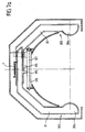
- La figure 6a montre selon une vue de dessus en coupe partielle un premier exemple de réalisation d'un troisième mode de réalisation du dispositif de sécurité selon l'invention,
- La figure 6b montre selon une vue de dessus en coupe partielle un deuxième exemple de réalisation d'un troisième mode de réalisation du dispositif de sécurité selon l'invention,
- La figure 7a montre selon une vue de dessus en coupe partielle une variante avantageuse du troisième mode de réalisation du dispositif de sécurité selon l'invention, dans lequel le récipient de travail n'est pas présent dans l'appareil,
- La figure 7b montre selon une vue de dessus en coupe partielle une variante avantageuse du troisième mode de réalisation du dispositif de sécurité selon l'invention, dans lequel le couvercle est disposé sur le récipient de travail,
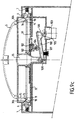
- La figure 8 montre selon une vue partielle de face en coupe une autre variante avantageuse de réalisation du dispositif de sécurité selon l'invention,
- La figure 9a montre selon une vue partielle de face en coupe une variante avantageuse de réalisation du dispositif de sécurité selon l'invention, lorsque le couvercle est ôté de l'appareil,
- La figure 9b montre selon une vue partielle de face en coupe la même variante avantageuse du dispositif de sécurité selon l'invention, après mise en place du couvercle,
- La figure 9c montre selon une vue partielle de face en coupe la même variante avantageuse du dispositif de sécurité selon l'invention, lors du retrait du couvercle,
- FIG. 1 shows, in a partial front view in section, an example of an embodiment of a first household appliance for preparing food according to the invention, in which the cover is placed on the working container,
- FIG. 2a shows in a partial side view in section a first embodiment of a second embodiment of the safety device according to the invention, in which the cover is lifted from the working container,
- FIG. 2b shows, in a partial side view in section, a first embodiment of a second embodiment of the safety device according to the invention, in which the cover is placed on the working container,
- FIG. 2c shows, in a partial side view in section, a first embodiment of a second embodiment of the safety device according to the invention, in which the cover is placed on the working container,
- FIG. 3a shows in a partial side view in section a second embodiment of a second embodiment of the safety device according to the invention, in which the cover is lifted from the working container,
- FIG. 3b shows in a partial side view in section a second embodiment of a second embodiment of the safety device according to the invention, in which the cover is placed on the working container,
- FIG. 4a shows in a partial side view in section a third embodiment of a second embodiment of the safety device according to the invention, in which the cover is lifted from the working container,
- FIG. 4b shows in a partial side view in section a third embodiment of a second embodiment of the safety device according to the invention, in which the cover is in contact with the working container,
- FIG. 4c shows, in a partial side view in section, a third exemplary embodiment of a second embodiment of the safety device according to the invention, in which the cover is placed on the working container,
- FIG. 5a shows in a partial side view in section a fourth embodiment of a second embodiment of the safety device according to the invention, in which the cover is lifted from the working container,
- FIG. 5b shows a top view of a fourth embodiment of a second embodiment of the security device according to the invention, in which a cover of the body of the device has been removed,
- FIG. 5c shows in a partial front view in section a detail of a fourth embodiment of a second embodiment of the safety device according to the invention, in which the cover is lifted from the working container,
- FIG. 6a shows a top view in partial section of a first embodiment of a third embodiment of the safety device according to the invention,
- FIG. 6b shows a top view in partial section of a second embodiment of a third embodiment of the safety device according to the invention,
- FIG. 7a shows a top view in partial section of an advantageous variant of the third embodiment of the safety device according to the invention, in which the working container is not present in the device,
- FIG. 7b shows a top view in partial section of an advantageous variant of the third embodiment of the safety device according to the invention, in which the cover is placed on the working container,
- FIG. 8 shows in a partial front view in section another advantageous alternative embodiment of the security device according to the invention,
- FIG. 9a shows in a partial front view in section an advantageous alternative embodiment of the safety device according to the invention, when the cover is removed from the device,
- FIG. 9b shows in a partial front view in section the same advantageous variant of the safety device according to the invention, after fitting the cover,
- FIG. 9c shows in a partial front view in section the same advantageous variant of the safety device according to the invention, when the cover is removed,
Le dispositif de sécurité selon l'invention est prévu pour être utilisé sur un appareil électroménager de préparation culinaire, du genre robot ménager.The safety device according to the invention is intended to be used on a household food preparation appliance, such as a food processor.
Tel que représenté aux figures 1 à 2c, un tel appareil comporte un corps 1
formant un socle 2 prévu pour recevoir un récipient de travail 3 d'axe de
symétrie x-x' dans lequel est susceptible d'être disposé un organe de travail
rotatif 4 entraíné par un moteur (non représenté auxdites figures) disposé dans
le corps 1, un couvercle 5 prévu pour fermer le récipient de travail 3, et des
moyens de verrouillage (non représentés auxdites figures) du couvercle 5 sur le
récipient de travail 3 disposé sur le socle 2.As shown in Figures 1 to 2c, such an apparatus comprises a
Le récipient de travail 3 comporte avantageusement une jupe périphérique
inférieure 13 prévue pour coopérer avec un rebord 9 ménagé dans le socle 2.
Le récipient de travail 3 comporte des parois latérales 28 et un fond 29 dans
lequel est ménagée une cheminée centrale 20 prévue pour le passage des
moyens d'entraínement de l'organe de travail 4. Avantageusement l'organe de
travail 4 se compose d'un moyeu 21 sur lequel est monté de manière connue
un outil de travail 22, tel que représenté aux figures 1 à 2c. Le moyeu 21
coopère avec une tige 19 montée dans le couvercle 5 pour stabiliser la rotation
de l'organe de travail 4.The working
Le moteur (non représenté aux figures) disposé dans le corps 1 de l'appareil
entraíne un axe de transmission 23, monté en regard d'un orifice 24 ménagé
dans le socle 2, et sur lequel est monté l'organe de travail 4, tel que représenté
à la figure 1.The motor (not shown in the figures) arranged in the
Le dispositif de sécurité comprend des moyens de détection de la présence du
couvercle 5 sur le récipient 3 disposé sur le socle 2. The security device comprises means for detecting the presence of the
Selon l'invention le dispositif de sécurité est susceptible d'être activé par la
simple mise en place du couvercle 5 sur le récipient 3 disposé sur le socle 2.According to the invention the security device is capable of being activated by the
simple fitting of the
Par le terme activé il convient d'entendre que le dispositif de sécurité autorise le
fonctionnement du moteur de l'appareil entraínant l'organe de travail 4. Par
l'expression simple mise en place du couvercle 5 mis en place sur le récipient 3
il convient d'entendre une mise en place du couvercle à l'aide d'un mouvement
simple de l'utilisateur, à l'exception de tout mouvement impliquant au moins
deux actions distinctes de l'utilisateur, par exemple poser le couvercle 5 sur le
récipient 3, puis tourner le couvercle 5 par rapport au récipient 3.By the term activated, it should be understood that the security device authorizes the
operation of the engine of the device driving the working member 4. By
the simple expression fitting the
Le couvercle 5 comporte une bague de détection prévue pour coopérer avec
au moins un détecteur disposé dans le corps 1.The
Avantageusement le dispositif comporte des moyens commandant le freinage
du moteur lorsque le couvercle 5 est retiré du récipient 3 disposé sur le socle 2.
Les moyens de freinage peuvent être commandés par exemple par la
disparition de l'activation du dispositif.Advantageously, the device comprises means controlling the braking
of the motor when the
Selon un exemple de réalisation d'un premier mode de réalisation, montré à la
figure 1, le dispositif de sécurité comporte des moyens magnétiques 300,
disposés sur la périphérie du couvercle 5, lesdits moyens étant susceptibles de
coopérer avec un détecteur magnétique 301 disposé dans le corps 1 et relié à
une électronique de détection 302, lorsque le couvercle 5 est mis en place sur
le récipient 3 disposé sur le socle 2. Les moyens magnétiques 300 peuvent
consister par exemple en une bande magnétique annulaire ou encore en une
pluralité d'éléments magnétiques disposés sur le couvercle 5 de manière à ce
qu'au moins un élément soit détecté par le détecteur 301 lorsque le couvercle 5
est mis en place sur le récipient 3 disposé sur le socle 2.According to an exemplary embodiment of a first embodiment, shown in the
FIG. 1, the safety device comprises
Dans ce premier mode de réalisation, la bague de détection est formée par les
moyens magnétiques 300 disposés sur le couvercle 5 et le détecteur disposé
dans le corps 1 est formé par le détecteur magnétique 301, lequel est relié à
l'électronique de détection 302. In this first embodiment, the detection ring is formed by the
Le fonctionnement de l'exemple de réalisation de ce premier mode de réalisation est le suivant.The operation of the exemplary embodiment of this first mode of achievement is as follows.
Le dispositif de sécurité est activé lorsque le couvercle 5 est correctement mis
en place sur le récipient 3 disposé sur le socle 2. Le détecteur magnétique 301
détecte la présence des moyens magnétiques 300 et autorise le
fonctionnement de l'appareil par l'intermédiaire du circuit électronique 302.The safety device is activated when the
Selon un deuxième mode de réalisation, le dispositif de sécurité comporte un
moyen de commande 320 monté dans le corps 1 et susceptible d'être actionné
par le couvercle 5 mis en place sur le récipient 3 disposé sur le socle 2, ainsi
qu'un moyen de protection 321 prévu pour s'interposer entre le corps 1 et le
récipient 3 lors de l'actionnement du moyen de commande 320, de manière à
prévenir l'actionnement du moyen de commande 320 par un moyen autre que
le couvercle 5. Ainsi l'utilisateur manipulant le moyen de commande 320 du
dispositif de sécurité à la main, ou à l'aide d'un outil tel qu'un manche de
couvert, ne pourra pas mettre en marche l'appareil.According to a second embodiment, the security device comprises a
control means 320 mounted in the
Selon un premier exemple de réalisation du deuxième mode de réalisation,
montré aux figures 2a à 2c, le dispositif de sécurité comporte une tige 160
montée dans le corps 1 pivotante sur un axe 161 sensiblement perpendiculaire
à l'axe de révolution x-x' du récipient 3, contre un moyen de rappel (non
représenté aux figures) entre une position d'attente représentée à la figure 2a
et une position active représentée à la figure 2c. La tige 160 comporte un
méplat 162 prévu pour coopérer avec un rebord 11 du couvercle 5,
avantageusement à travers une ouverture 168 ménagée dans le corps 1, ledit
méplat formant le moyen de commande 320. La tige 160 comporte également
une patte 163 prévue pour actionner un microrupteur 164 lorsque le couvercle
5 est mis en place sur le récipient 3 disposé sur le socle 2. Tel que montré aux
figures 2a à 2c le rebord 11 se présente sous la forme d'une collerette. Le
moyen de rappel est prévu pour ramener la tige 160 dans une position d'attente
représentée à la figure 2a dans laquelle le rebord 11 du couvercle 3 est
susceptible d'actionner le méplat 162. Cette disposition des moyens de sécurité
présente l'avantage d'être indépendante des moyens de verrouillage du
couvercle 5 sur le récipient de travail 3 disposé sur le socle 2. La tige 160
présente une surface convexe 167, avantageusement cylindrique, laquelle
s'étend à l'extérieur du corps 1 lorsque la patte 163 actionne le microrupteur
164. Cette disposition rend difficile l'actionnement de la tige 160 par un moyen
autre que le rebord 11 du couvercle 5. La surface 167 forme un moyen de
protection 321 s'interposant entre le corps 1 et le récipient 3 lors de
l'actionnement du méplat 162 formant le moyen de commande 320.
Avantageusement encore un deuxième microrupteur 166 monté dans le corps
1 de l'appareil est prévu pour détecter la présence correcte du récipient 3 sur le
socle 2.According to a first embodiment of the second embodiment,
shown in Figures 2a to 2c, the safety device comprises a
Le fonctionnement de ce premier exemple de réalisation est le suivant. Le
rebord 11 appuyant sur le méplat 162 entraíne la rotation de la tige 160 dont la
patte 163 actionne le microrupteur 164. La surface convexe 167 de la tige 160
protège le méplat 162.The operation of this first exemplary embodiment is as follows. The
Selon un deuxième exemple de réalisation du deuxième mode de réalisation,
montré aux figures 3a et 3b, le dispositif de sécurité comporte une glissière 250
montée coulissante, selon une direction sensiblement parallèle à la direction
d'introduction du couvercle 5 sur le récipient 3, sur le corps 1 contre un moyen
de rappel 256 entre une position d'attente représentée à la figure 3a et une
position active représentée à la figure 3b.According to a second embodiment of the second embodiment,
shown in Figures 3a and 3b, the safety device includes a
La glissière 250 comporte une patte 251 susceptible de coopérer avec un
rebord 11 du couvercle 5. Tel que montré aux figures 3a et 3b le rebord 11 se
présente sous la forme d'une collerette. La glissière 250 comporte une
crémaillère 252 coopérant par l'intermédiaire d'une roue dentée 253 avec une
crémaillère 254 ménagée longitudinalement sur une cornière 255 avantageusement
semi-circulaire. La glissière 250 forme le moyen de commande 320 et la
cornière 255 forme le moyen de protection 321. La glissière 250 coopère dans
la position active avec un bouton de commande 259 d'un microrupteur 258
activant le dispositif de sécurité. Dans la position active représentée à la figure
3b la cornière 255 est prévue pour protéger la patte 251 d'un actionnement,
intentionnel ou non, autre que celui commandé par le rebord 11 du couvercle 5. The
Avantageusement le rebord 11 comporte une remontée 257 rendant encore
plus difficile l'actionnement intentionnel de la patte 251.Advantageously, the
Le fonctionnement de ce deuxième exemple de réalisation est le suivant. Le
rebord 11 appuyant sur la patte 251 déplace la glissière 250 laquelle actionne
le microrupteur 258. La cornière 255 entraínée par la glissière 250 protège la
glissière 250 et la patte 251.The operation of this second exemplary embodiment is as follows. The
Si l'utilisateur cherche à actionner la patte 251 avec un outil, la cornière 255
entraínée en rotation frappe latéralement l'outil et le chasse de la patte 251
avant que le microrupteur n'active le dispositif de sécurité autorisant la mise en
route de l'appareil.If the user seeks to actuate the
Selon un troisième exemple de réalisation du deuxième mode de réalisation,
montré aux figures 4a à 4c, le dispositif de sécurité comporte une glissière 260
montée coulissante, selon une direction sensiblement parallèle à la direction
d'introduction du couvercle 5 sur le récipient 3, sur le corps 1 entre une position
d'attente représentée à la figure 4a et une position active représentée à la
figure 4c.According to a third exemplary embodiment of the second embodiment,
shown in Figures 4a to 4c, the safety device comprises a
La glissière 260 comporte un rebord 261 susceptible de coopérer avec un
rebord 11 du couvercle 5. Tel que montré aux figures 4a à 4c le rebord 11 se
présente sous la forme d'une collerette. La glissière 260 comporte une butée
262 susceptible de coopérer avec un premier bras 263 d'une pièce 264 montée
pivotante sur un axe 265 sensiblement perpendiculaire à l'axe de révolution x-x'
du récipient 3. La pièce 264 comprend un second bras 266 susceptible
d'actionner un bouton de commande 267 d'un microrupteur 268, lorsque le
rebord 11 du couvercle 5 mis en place sur le récipient 3 coopère avec le rebord
261 de la glissière 260. La pièce 264 comporte un volet 269 avantageusement
incurvé et préférentiellement de géométrie cylindrique prévu pour sortir du
corps 1 par une ouverture 270. La glissière 261 forme le moyen de commande
320 et le volet 269 forme le moyen de protection 321. La glissière 250 coopère
dans la position active avec le bouton de commande 267 du microrupteur 268
activant le dispositif de sécurité. Dans la position active représentée à la figure
4c le volet 269 est prévu pour protéger la patte 251 d'un actionnement,
intentionnel ou non, autre que celui commandé par le rebord 11 du couvercle 5.
Avantageusement un moyen de rappel 272 est monté entre la glissière 260 et
la pièce 264. Avantageusement encore le moyen de rappel 272 est monté de
manière à ce que la position intermédiaire représentée à la figure 4b présente
un point dur.The
Le fonctionnement de ce troisième exemple de réalisation est le suivant. Le
rebord 11 appuyant sur le rebord 261 déplace la glissière 260, laquelle
actionne le microrupteur 268. Le volet 269 entraíné par la glissière 260 protège
la glissière 260 et le rebord 261.The operation of this third exemplary embodiment is as follows. The
Si l'utilisateur cherche à actionner le rebord 261 avec un outil, le volet 269
entraíné en rotation frappe latéralement l'outil et le chasse du rebord 261 avant
que le microrupteur n'active le dispositif de sécurité autorisant la mise en route
de l'appareil.If the user seeks to actuate the
Selon un quatrième exemple de réalisation du deuxième mode de réalisation,
montré aux figures 5a à 5c, le moyen de commande 320 du dispositif de
sécurité comporte une bascule 343 commandant un microrupteur 350.According to a fourth embodiment of the second embodiment,
shown in FIGS. 5a to 5c, the control means 320 of the device
security comprises a
La figure 5a montre dans le corps 1 de l'appareil la bascule 343 montée
pivotante sur un axe 353. Une extrémité de la bascule 343 est susceptible
d'être actionnée par un rebord 11 du couvercle 5. Le couvercle 5 comporte une
jupe 15 présentant un épaulement 348 et se termine par une extrémité 358
formant le rebord 11. L'extrémité opposée de la bascule 343 comporte un
logement dans lequel pivote un axe 354 d'un organe de commande 344. Un
bras d'actionnement 342 est monté mobile dans le corps 1 entre une position
rentrée dans laquelle le couvercle 5 peut être mis en place sur le récipient de
travail 3 et une position sortie dans laquelle une extrémité du bras
d'actionnement 342 vient recouvrir partiellement l'épaulement 348 du couvercle
5. Une extrémité de l'organe de commande 344 est prévue pour actionner le
bouton du microrupteur 350 alors que l'autre extrémité coopère avec le bras
d'actionnement. Figure 5a shows in the
Le dispositif de sécurité est associé à des moyens de verrouillage du couvercle
5 sur le récipient 3, lesdits moyens de verrouillage étant mis en oeuvre par un
déplacement du couvercle 5 dans le sens vertical. Un bouton de déverrouillage
35 des moyens de verrouillage est monté mobile dans le corps 1 entre une
position enfoncée de déverrouillage dans laquelle le couvercle 5 peut être mis
en place ou retiré et une position relevée dans laquelle le couvercle 5 est
verrouillé sur le récipient de travail 3. Dans la figure 5a le bras d'actionnement
342 est en position rentrée et le bouton de déverrouillage 35 est représenté en
position de déverrouillage. Le bouton 35 comporte une surface de came 355
susceptible d'être actionnée par le bras d'actionnement 342. Un capot 351
monté sur le corps 1 recouvre les éléments du dispositif de verrouillage.The security device is associated with means for locking the cover.
5 on the
La figure 5b montre que le corps 1 comporte deux bras 341 entre lesquels peut
être disposé le récipient de travail (non montré à la figure). Sur chacun des bras
341 est monté une mâchoire 106 prévue pour verrouiller le couvercle sur le
récipient de travail. Le bras d'actionnement 342 se prolonge dans chaque bras
341 par une tige 347 dont l'extrémité 357 est susceptible de coopérer avec la
mâchoire 106. Des ressorts 352 sont prévus pour déplacer le bras
d'actionnement 342 en position sortie en direction du récipient de travail.FIG. 5b shows that the
La figure 5c montre une mâchoire 106 montée mobile en rotation sur un axe
346. La mâchoire 106 comporte une encoche 356 prévue pour recevoir
l'extrémité 357 de la tige 347 du bras d'actionnement 342. La mâchoire 106
comporte également une découpe 349 prévue pour coopérer avec le rebord 11
du couvercle 5. La mâchoire 106 présente un balourd formant un moyen de
rappel tendant à ramener ladite mâchoire dans la position déverrouillée. A titre
de variante, non montrée aux figures, le moyen de rappel peut être un moyen
de rappel élastique.FIG. 5c shows a
Le fonctionnement de ce quatrième exemple de réalisation est le suivant. Le
rebord 11 du couvercle 5 mis en place sur le récipient 3 actionne à la fois la
bascule 343 et les mâchoires 106. La bascule 343 pivote sur l'axe 353 et
rapproche l'organe de commande 344 du microrupteur 350. Les mâchoires 106
pivotent sur les axes 346 et les extrémités 357 des tiges 347 du bras
d'actionnement 342 entrent dans les encoches 356. Le bras d'actionnement
342 prend sa position sortie sous l'action des ressorts 352, position dans
laquelle il vient recouvrir partiellement l'épaulement 348 du couvercle 5. Lors de
ce déplacement le bras d'actionnement 342 entraíne la remontée du bouton de
déverrouillage 35 en position verrouillée par l'intermédiaire de la came 355, et
actionne l'organe de commande 344 qui vient commander le microrupteur 350.The operation of this fourth exemplary embodiment is as follows. The
Si l'utilisateur cherche à actionner la bascule 343 alors que les mâchoires 106
sont en position d'attente, le bras d'actionnement 342 bloqué par les mâchoires
106 empêche l'actionnement de l'organe de commande 344. Le dispositif de
sécurité ne peut être activé pour faire fonctionner l'appareil. Si l'utilisateur
actionne les mâchoires 106 pour les amener en position de verrouillage, le bras
d'actionnement 342 repoussé par les ressorts 352 vient protéger la bascule
343 et l'utilisateur ne peut pas l'atteindre.If the user seeks to operate the
En résumé, dans le deuxième mode de réalisation présenté, la bague de
détection est formée sur le couvercle 5 par le rebord 11, le détecteur disposé
dans le corps 1 étant formé par le moyen de commande 320, lequel commande
le microrupteur 164 ; 258 ; 268 ; 350.In summary, in the second embodiment presented, the ring
detection is formed on the
De manière générale, le fonctionnement de ce second mode de réalisation est
le suivant. Le dispositif de sécurité est activé lorsque le couvercle 5 est
correctement mis en place sur le récipient 3 disposé sur le socle 2. Le rebord
11 du couvercle 5 actionne le moyen de commande 320. L'utilisateur voulant
actionner le moyen de commande 320 voit son action entravée par le moyen
de protection 321 s'interposant entre le corps 1 et le récipient 3, de manière à
prévenir l'actionnement du moyen de commande 320 par un moyen autre que
le couvercle 5.In general, the operation of this second embodiment is
the following. The safety device is activated when the
Selon un troisième mode de réalisation dont deux exemples de réalisations
sont représentés respectivement aux figures 6a et 6b, le dispositif de sécurité
comporte au moins deux capteurs de commande 302 disposés dans le corps 1,
et susceptibles d'actionner au moins un microrupteur 91; 153, 154, lesdits
capteurs comprenant chacun au moins une tête 306 susceptible d'occuper une
position sortie dans laquelle le microrupteur n'autorise pas le fonctionnement
de l'appareil, lesdites têtes étant susceptibles d'être déplacées par le couvercle
5 mis en place sur le récipient 3 disposé sur le socle 2 vers une position rentrée
dans laquelle le microrupteur autorise le fonctionnement de l'appareil.According to a third embodiment, including two examples of embodiments
are shown in Figures 6a and 6b respectively, the safety device
comprises at least two
Selon l'exemple de réalisation présenté à la figure 6a, chacune des deux têtes
306 est prolongée par un bras 31, 32 comportant chacun un bossage 90 prévu
pour libérer un bouton de commande 92 d'un microrupteur 91. Le microrupteur
est prévu pour activer le dispositif lorsque le bouton est libéré par chacun des
deux bossages 90. Le premier bras 31 coulisse axialement sur le second bras
32. Chacune des deux têtes 306 est avantageusement montée mobile contre
un moyen de rappel 7.According to the exemplary embodiment presented in FIG. 6a, each of the two
Le fonctionnement de cet exemple de réalisation est le suivant. Le dispositif de
sécurité est activé lorsque le couvercle 5 est correctement mis en place sur le
récipient 3 disposé sur le socle 2. Les têtes 306 repoussées par le couvercle 5
actionnent par l'intermédiaire des bras 31, 32 le ou les microrupteurs 91; 153,
154. L'utilisateur a besoin de ses deux mains pour actionner les deux têtes
306. Ainsi l'actionnement par mégarde d'une des deux têtes par l'utilisateur
n'est pas susceptible d'activer le dispositif de sécurité et de rendre possible la
mise en marche de l'appareil. L'utilisateur doit repousser chacune des têtes
306 pour que chacun des bossages 90 libère le bouton de commande 92 du
microrupteur 91.The operation of this exemplary embodiment is as follows. The device
security is activated when the
Selon l'exemple de réalisation présenté à la figure 6b chaque bras 31, 32 est
articulé. Chacun des bras 31, 32 est monté sur un pivot 51, 52 et comporte un
premier membre 53, 54 comprenant une lumière 55, 56 coopérant avec un
ergot 57, 58 monté sur chacune des têtes 306. Chaque bras 31, 32 comporte
également un second membre 61, 62 comprenant une lumière 63, 64
coopérant avec un ergot 65, 66 monté sur une glissière 67, 68. Chaque
glissière 67, 68 comporte un bossage 151, 152 prévu pour commander un
microrupteur 153, 154 lorsque les têtes 306 sont en position rentrée. Chacune
des deux têtes 306 est avantageusement montée mobile contre un moyen de
rappel 7. According to the exemplary embodiment presented in FIG. 6b, each
Le fonctionnement de cet exemple de réalisation est le suivant. L'utilisateur doit
repousser chacune des têtes 306 pour que chacun des bossages 151 ; 152
actionne le microrupteur 153 ; 154.The operation of this exemplary embodiment is as follows. User must
push each of the
Selon une variante avantageuse de l'invention, le dispositif de sécurité
comporte, associé aux deux capteurs de commande 302 comportant chacun
une tête 306, un moyen de commande 320 prévu pour actionner un
microrupteur 330. Tel que représenté aux figures 7a et 7b, chacune des deux
têtes 306 est prolongée par l'un des bras 31, 32 formant l'un des capteurs 302,
le premier bras 31 coulissant axialement sur le second bras 32, un moyen de
rappel 7 est monté entre lesdits bras. Chaque bras 31, 32 porte un ergot 315
susceptible de coopérer avec une patte 316 issue du moyen de commande 320
lorsque les têtes 306 sont en position sortie de manière à empêcher le
déplacement dudit moyen de commande. Le moyen de protection 321 n'est
plus nécessaire.According to an advantageous variant of the invention, the security device
comprises, associated with the two
Le fonctionnement de la variante représentée aux figures 7a et 7b est le
suivant. Lorsque le couvercle 5 repousse les têtes 306 les ergots 315 dégagent
la patte 316 et le moyen de commande 320 peut actionner le microrupteur 330.
Sans couvercle l'utilisateur ne peut involontairement actionner à la fois les têtes
306 et le moyen de commande 320. La combinaison des têtes 306 avec le
moyen de commande 320 renforce encore la sécurité.The operation of the variant shown in Figures 7a and 7b is the
next. When the
Selon deux autres variantes avantageuses de l'invention, représentées aux
figures 8, 9a, 9b et 9c, les moyens de verrouillage comportent au moins deux
mâchoires 6 montées mobiles à l'encontre d'au moins un moyen de rappel
entre une position de verrouillage, correspondant à leur position de rappel, et
une position de déverrouillage.According to two other advantageous variants of the invention, shown in
Figures 8, 9a, 9b and 9c, the locking means comprise at least two
Les moyens de verrouillage sont susceptibles d'être amenés en position de
déverrouillage grâce à des moyens de déverrouillage montés mobiles entre une
position de repos dans laquelle les mâchoires 6 sont susceptibles de verrouiller
le couvercle 5 sur le corps 1, et une position active, dans laquelle les mâchoires
6 occupent leur position de déverrouillage. Chacune des mâchoires 6 forme
l'une des têtes 306. Avantageusement chaque mâchoire 6 est associée à un
moyen de rappel 7.The locking means are capable of being brought into the position of
unlocking by means of unlocking mounted movable between a
rest position in which the
Le couvercle 5 comporte une jupe périphérique 15 présentant au moins un
rebord 11 prévu pour coopérer avec les mâchoires 6. Avantageusement le
rebord 11 est périphérique. Cette disposition permet de présenter le couvercle
5 sur le récipient de travail 3 sans orientation angulaire préférentielle. Selon
une variante de réalisation, non montrée aux figures, au moins l'un des rebords
11 est formé par la paroi inférieure d'une cavité, débouchante ou non,
ménagée dans la paroi de la jupe 15.The
Tel que montré à la figure 8, les mâchoires 6 sont montées mobiles radialement
dans des logements 12 du corps 1 desquels elles sont susceptibles de
déboucher par des ouvertures 25.As shown in Figure 8, the
Chaque rebord 11 présente de manière avantageuse un méplat supérieur 16
prévu pour coopérer avec un méplat inférieur 17 ménagé sur chacune des
mâchoires 6. Avantageusement chaque rebord 11 comporte un chanfrein
inférieur 18 prévu pour repousser la mâchoire 6 contre le moyen de rappel 7
lors de la mise en place du couvercle 5 sur le récipient de travail 3.
Avantageusement encore chaque mâchoire 6 comporte un chanfrein supérieur
14 prévu pour faciliter le glissement du rebord 11 sur ladite mâchoire lors de la
mise en place du couvercle 5 sur le récipient de travail 3.Each
Un bouton de déverrouillage 35 monté dans le corps 1 contre un moyen de
rappel 36 comporte deux surfaces de came 37, 38 susceptibles de repousser
respectivement une première surface de came 39 ménagée sur le premier bras
31 et une deuxième surface de came 40 ménagée sur le second bras 32, le
premier bras 31 comportant une ouverture 41 prévue pour le passage de la
deuxième surface de came 40 ou de la surface de came 38, tel que représenté
aux figures 5 et 6.An unlocking
Tel que représenté à la figure 8, le bouton de déverrouillage 35 est mobile à
l'encontre du moyen de rappel 36 entre une position de repos, dans laquelle les
mâchoires 6 sont susceptibles de verrouiller le couvercle 5 sur le récipient 3, et
une position active correspondant à la position de rappel, dans laquelle les
mâchoires 6 occupent leur position de déverrouillage et le couvercle 5 peut être
retiré du récipient 3. Le bouton de déverrouillage 35 coopère avec un frein 110.
Le bouton de déverrouillage 35 comporte une surface de came 111 actionnant
un organe de commande 112 du frein lorsque le bouton 35 est amené en
position active.As shown in Figure 8, the
Le fonctionnement de la variante représentée à la figure 8 est le suivant. Le
retrait du couvercle 5 désactive le dispositif de sécurité. De manière
avantageuse la commande du retrait du couvercle 5 associée à un système de
verrouillage par mâchoires 6 commande le freinage de l'organe de travail.
L'utilisateur appuyant sur le bouton de déverrouillage 35 actionne le bouton
poussoir 112 du frein 110 permettant d'arrêter l'organe de travail.
Avantageusement, les moyens de déverrouillage sont susceptibles de
commander successivement le frein 110 prévu pour immobiliser l'organe de
travail, puis les moyens de commande de l'ouverture des mâchoires 6.The operation of the variant shown in Figure 8 is as follows. The
removing
Tel que représenté aux figures 9a à 9c, le bouton de déverrouillage 35 coopère
avec une bascule 100 montée contre un moyen de rappel 107. La bascule
comporte un appui 104 prévu pour coopérer avec des bossages 102 ménagés
sur les bras 31, 32, et coopère avec un microrupteur 103. L'une des extrémités
108 de la bascule 100 est susceptible d'être actionnée par le bouton de
déverrouillage 35 alors que l'autre extrémité 109 de la bascule 100 est
susceptible d'actionner un bouton 105 du microrupteur 103. Le moyen de
rappel 107 est monté entre l'extrémité 108 coopérant avec le bouton de
déverrouillage et l'appui 104. Le microrupteur 103 peut commander un frein, un
autre moyen étant prévu pour commander le dispositif. Le microrupteur peut
aussi commander le dispositif de sécurité, et avantageusement un frein. Le
bouton de déverrouillage 35 monté dans le corps 1 contre un moyen de rappel
36 comporte également deux surfaces de came 37, 38 susceptibles de
repousser respectivement une première surface de came 39 ménagée sur le
premier bras 31 et une deuxième surface de came 40 ménagée sur le second
bras 32, formant les moyens de commande de l'ouverture des mâchoires 6. As shown in Figures 9a to 9c, the
Le fonctionnement de la variante de réalisation représentée aux figures 9a à 9c
est le suivant. Lorsque l'utilisateur appuie sur le bouton 35, la bascule 100
pivote sur l'appui 104 et libère le bouton 105 du microrupteur commandant
avantageusement un frein avant que les surfaces de came 37, 38 du bouton 35
ne coopèrent avec les surfaces de came 39, 40 des bras 31,32 pour libérer les
mâchoires 6.The operation of the alternative embodiment shown in Figures 9a to 9c
is the next. When the user presses the
En résumé, dans le troisième mode de réalisation présenté, la bague de
détection est formée par un bord périphérique du couvercle 5, le détecteur
monté dans le corps étant formé par les têtes 306, lesquelles commandent le(s)
microrupteur(s) 61 ; 153, 154 ; 103.In summary, in the third embodiment presented, the ring
detection is formed by a peripheral edge of the
L'invention n'est nullement limitée strictement aux exemples de réalisation décrits précédemment, mais englobe de nombreuses modifications ou améliorations.The invention is in no way strictly limited to the exemplary embodiments described above, but includes many modifications or improvements.
Notamment, à titre d'exemple complémentaire on peut envisager de remplacer
la cheminée centrale 20 par une traversée étanche de paroi permettant la
transmission du mouvement à l'outil, tel que connu sur les appareils
électroménagers de type mélangeurs, prévus pour la réalisation de
préparations liquides.In particular, as a further example, we can consider replacing
the
Un frein peut être également associé au premier ou au deuxième mode de réalisation.A brake can also be associated with the first or second mode of production.
L'invention peut être aussi appliquée à un dispositif de sécurité pour un appareil comportant un récipient et un couvercle dont la géométrie n'est pas de révolution, ou à un récipient et à un couvercle dont les parties en regard ne présentent pas d'axe de symétrie et nécessitent un indexage du couvercle sur le récipient selon une position donnée.The invention can also be applied to a security device for a appliance comprising a container and a cover the geometry of which is not revolution, or to a container and a lid whose opposite parts do not have no axis of symmetry and require indexing of the cover on the container in a given position.
L'invention peut être aussi appliquée à un dispositif de sécurité pour un appareil comportant un récipient et un couvercle dont les parties en regard présentent un axe de symétrie, le corps du récipient et/ou du couvercle n'étant pas de révolution, mais permettant une liberté de positionnement en rotation du couvercle sur le récipient lors de l'introduction du couvercle sur le récipient. The invention can also be applied to a security device for a device comprising a container and a cover, the opposite parts have an axis of symmetry, the body of the container and / or of the cover being no revolution, but allowing freedom of positioning in rotation of the lid on the container when inserting the lid on the container.
La liberté de positionnement en rotation peut être totale (sur 360°) ou multiple (selon plusieurs positions).Freedom of positioning in rotation can be total (over 360 °) or multiple (in several positions).
A titre de variante, la bague de détection peut être remplacée par au moins une portion de bague de détection, permettant une certaine liberté de positionnement en rotation du couvercle sur le récipient lors de l'introduction du couvercle sur le récipient.Alternatively, the detection ring can be replaced by at least one detection ring portion, allowing a certain freedom of rotational positioning of the lid on the container during the introduction of the lid on the container.
La liberté de positionnement en rotation est alors partielle (sur un ou plusieurs secteurs angulaires).Freedom of positioning in rotation is then partial (on one or more angular sectors).
L'invention peut être également appliquée à un dispositif de sécurité pour un appareil comportant un récipient et un couvercle mis en place sur le récipient par un mouvement uniaxial selon un axe incliné, distinct de l'axe vertical.The invention can also be applied to a security device for a apparatus comprising a container and a lid placed on the container by a uniaxial movement along an inclined axis, distinct from the vertical axis.
La présente invention concerne également un appareil électroménager de
préparation culinaire, du genre robot ménager, comportant un corps 1 formant
un socle 2 prévu pour recevoir un récipient de travail 3 dans lequel est
susceptible d'être disposé un organe de travail rotatif 4 entraíné par un moteur
disposé dans le corps 1, un couvercle 5 prévu pour fermer le récipient de travail
3, et des moyens de verrouillage du couvercle 5 sur le récipient de travail 3
disposé sur le socle 2, comportant un tel dispositif de sécurité.The present invention also relates to a household appliance of
food preparation, of the food processor type, comprising a
L'invention trouve son application dans le domaine technique général des appareils électroménagers de préparation culinaire, du genre robot ménagers multi-usages.The invention finds its application in the general technical field of household food preparation appliances, such as food processors multi-purpose.
Claims (15)
- A safety device associated with a lid having detector elements for a domestic electrical food-preparing appliance of the food processor type comprising a body (1) forming a base (2) designed to receive a working receptacle (3) in which there may be placed a rotary working member (4) driven by a motor disposed in the body (1), a lid (5) designed to close the working receptacle (3), the facing portions of the lid (5) and of the working receptacle (3) presenting an axis of symmetry, the lid (5) being suitable for being put into place on the working receptacle (3) by being moved axially, said safety device comprising a detector element in the lid (5) designed to co-operate with detector means (301, 320, 306) for detecting the presence of the lid (5) on the receptacle (3) disposed on the base (2), said detector means (301, 320, 306) being disposed in the body (1), the safety device being characterized in that the detector means (301, 320, 306) comprise at least one detector designed to co-operate with at least a portion of a detector ring belonging to the lid (5).
- A safety device according to claim 1, characterized in that the detector means (301, 320, 306) comprise at least one detector designed to co-operate with a detector ring belonging to the lid (5).
- A safety device according to claim 1 or claim 2, characterized in that the detector means comprise a magnetic detector (301) designed to co-operate with magnetic means (300) disposed on the periphery of the lid (5), when the lid (5) is put into place on the receptacle (3) placed on the base (2), the magnetic detector (301) being connected to an electronic detector circuit (302).
- A safety device according to claim 1 or claim 2, characterized in that the detector means comprise controller means (320) suitable for being activated by a rim (11) of the lid (5) bought into place on the receptacle (3) placed on the base (2).
- A safety device according to claim 4, characterized in that it comprises a rocker (343) controlling a microswitch (350), the rocker (343) being mounted in the body (1) with one end thereof being suitable for being activated by the rim (11) of the lid (5).
- A safety device according to claim 4 or claim 5, characterized in that it includes protector means (321) designed to be interposed between the body (1) and the receptacle (3) during actuation of the control means (320).
- A safety device according to claim 6, characterized in that it includes an actuator arm (342) mounted to move in the body (1) against springs (352) between a retracted position and an extended position corresponding to the return position, in which one end of the actuator arm (342) partially overlaps a shoulder (348) of the lid (5).
- A safety device according to claim 1 or claim 2, characterized in that the detector means comprise at least two control sensors (302) suitable for actuating at least one microswitch (91; 103; 153, 154; 330), each of said sensors having at least one head (306) suitable for occupying an extended position in which the microswitch does not allow the appliance to operate, said heads being suitable for being moved towards a retracted position by the lid (5) being put into place on the receptacle (3) placed on the base (2), in which retracted position the microswitch allows the appliance to operate.
- A safety device according to claim 8, characterized in that each control sensor (302) comprises an arm (31, 32), each having at least one of the heads (306) mounted thereon.
- A safety device according to claim 8 or claim 9, characterized in that it includes control means (320) suitable for actuating the microswitch (330), and carrying a tab (316) suitable for co-operating with lugs (315) carried by the sensors (302) when the heads (306) are in the extended position.
- A safety device according to anyone of claims 8 to 10, characterized in that the heads (306) form jaws (6) for locking the lid (5) on the receptacle (3).
- A safety device according to claim 11, characterized in that each head (306) as a bottom flat (17) designed to co-operate with a peripheral rim (11) formed on the lid (5).
- A domestic electrical food-preparing appliance of the food processor type comprising a body (1) forming a base (2) for receiving a working receptacle (3) in which there may be placed a rotary working member (4) driven by a motor disposed in the body (1), a lid (5) provided to close the working receptacle (3), and locking means (6, 106) for locking the lid (5) closing the working receptacle (3) when placed on the base (2), the facing portions of the lid (5) and of the working receptacle (3) presenting an axis of symmetry, the lid (5) being suitable for being put into place on the working receptacle (3) by being moved axially, the appliance being characterized in that it includes a safety device according to any one of claims 1 to 10, and in that the locking means comprise at least two jaws (6; 106) mounted to move against at least one return means between a locking position, corresponding to their retracted position, and an unlocking position, and in that the locking means are suitable for being brought into the unlocking position by unlocking means (35) mounted to move between a rest position in which the jaws (6, 106) are capable of locking the lid (5) on the body (1), and an active position in which the jaws (6, 106) occupy their unlocking position.
- A domestic electrical food-preparing appliance according to claim 13, characterized in that the unlocking means (35) are suitable for operating in succession a brake provided for preventing the working member from moving, and then control means for opening the jaws (6).
- A domestic electrical food-preparing appliance according to claim 13 or claim 14, characterized in that it includes a safety device according to claim 7, the unlocking means (35) including a camming surface (355) co-operating with the actuator arm (342), the jaws (106) being mounted to move in rotation on the body (1) against return means, each jaw (106) having a notch (356) designed to receive one end (357) of a rod (347) extending the actuator arm (342).
Applications Claiming Priority (3)
| Application Number | Priority Date | Filing Date | Title |
|---|---|---|---|
| FR9712567A FR2769199B1 (en) | 1997-10-03 | 1997-10-03 | SAFETY DEVICE FOR HOUSEHOLD HOUSEHOLD KITCHEN APPLIANCE, AND APPARATUS COMPRISING SUCH A DEVICE |
| FR9712567 | 1997-10-03 | ||
| PCT/FR1998/002114 WO1999017646A1 (en) | 1997-10-03 | 1998-10-02 | Safety device for household electric cooking appliance, such as a food processor, and appliance comprising said device |
Publications (2)
| Publication Number | Publication Date |
|---|---|
| EP1018917A1 EP1018917A1 (en) | 2000-07-19 |
| EP1018917B1 true EP1018917B1 (en) | 2004-02-18 |
Family
ID=9511984
Family Applications (1)
| Application Number | Title | Priority Date | Filing Date |
|---|---|---|---|
| EP98947594A Expired - Lifetime EP1018917B1 (en) | 1997-10-03 | 1998-10-02 | Safety device for household electric cooking appliance, such as a food processor, and appliance comprising said device |
Country Status (5)
| Country | Link |
|---|---|
| EP (1) | EP1018917B1 (en) |
| AU (1) | AU9445398A (en) |
| DE (1) | DE69821781T2 (en) |
| FR (1) | FR2769199B1 (en) |
| WO (1) | WO1999017646A1 (en) |
Cited By (1)
| Publication number | Priority date | Publication date | Assignee | Title |
|---|---|---|---|---|
| CN104540429A (en) * | 2012-08-16 | 2015-04-22 | 德国福维克控股公司 | Electrically operated kitchen appliance |
Families Citing this family (9)
| Publication number | Priority date | Publication date | Assignee | Title |
|---|---|---|---|---|
| DE19912750A1 (en) | 1999-03-22 | 2000-09-28 | Braun Gmbh | Safety device for a cup mixer |
| FR2808664B1 (en) * | 2000-05-12 | 2002-07-26 | Seb Sa | HOUSEHOLD APPLIANCE FOR FOOD PREPARATION COMPRISING A JAW LOCKING DEVICE ON THE CONTAINER |
| FR2818525B1 (en) * | 2000-12-27 | 2003-09-05 | Seb Sa | HOUSEHOLD APPLIANCE FOR FOOD PREPARATION COMPRISING A SIMPLIFIED LOCKING DEVICE OF A LID ON A CONTAINER |
| FR2820020B1 (en) | 2001-01-30 | 2003-10-31 | Moulinex Sa | SAFETY DEVICE FOR HOUSEHOLD APPLIANCES |
| US6609821B2 (en) | 2001-04-13 | 2003-08-26 | Sunbeam Products, Inc. | Blender base with food processor capabilities |
| DE102009003118A1 (en) * | 2009-05-14 | 2010-11-18 | BSH Bosch und Siemens Hausgeräte GmbH | Kitchen appliance with safety device |
| DE102011051149B4 (en) * | 2010-09-30 | 2019-09-12 | Vorwerk & Co. Interholding Gmbh | Electrically operated food processor with a cooking vessel |
| FR2995774B1 (en) * | 2012-09-26 | 2014-09-26 | Seb Sa | DOMESTIC ELECTRICAL COOKING APPLIANCE |
| DE102012111805A1 (en) * | 2012-12-05 | 2014-06-05 | Vorwerk & Co. Interholding Gmbh | Electrically operated food processor |
Family Cites Families (9)
| Publication number | Priority date | Publication date | Assignee | Title |
|---|---|---|---|---|
| FR2340706A1 (en) | 1976-02-12 | 1977-09-09 | Moulinex Sa | APPLIANCE EQUIPPED WITH A REMOVABLE ACCESSORY SUCH AS A VEGETABLE CUTTER |
| DE2651237C2 (en) | 1976-11-10 | 1984-02-02 | Vorwerk & Co Interholding Gmbh, 5600 Wuppertal | Safety interlocking and monitoring device on household mixers |
| FR2447703A1 (en) | 1979-02-01 | 1980-08-29 | Seb Sa | Safety system for electrically operated mincer - comprises switch in motor supply circuit operated by lid locking mechanism |
| FR2513870A1 (en) * | 1981-10-02 | 1983-04-08 | Dito Sama | WORKING MACHINE FOR FOOD AND OTHER PRODUCTS, PARTICULARLY FOR CHOPPING AND MIXING |
| DE3311291A1 (en) * | 1983-03-28 | 1984-10-04 | Braun Ag, 6000 Frankfurt | MAGNETIC SAFETY DEVICE, ESPECIALLY FOR A KITCHEN EQUIPMENT |
| DE3540370A1 (en) * | 1985-11-14 | 1987-05-21 | Braun Ag | Safety device for kitchen appliances |
| FR2601576B1 (en) * | 1986-07-16 | 1990-05-18 | Robot Coupe Sa | HOPPER FOR FEEDING FOOD INTO A FOOD PROCESSING APPARATUS. |
| DE4128456A1 (en) * | 1991-08-28 | 1993-03-04 | Braun Ag | CRUSHING DEVICE FOR AN ELECTRICAL KITCHEN MACHINE |
| ATE128020T1 (en) | 1992-01-01 | 1995-10-15 | Maweva Holding Ag | KITCHEN MACHINE. |
-
1997
- 1997-10-03 FR FR9712567A patent/FR2769199B1/en not_active Expired - Fee Related
-
1998
- 1998-10-02 EP EP98947594A patent/EP1018917B1/en not_active Expired - Lifetime
- 1998-10-02 DE DE1998621781 patent/DE69821781T2/en not_active Expired - Fee Related
- 1998-10-02 AU AU94453/98A patent/AU9445398A/en not_active Abandoned
- 1998-10-02 WO PCT/FR1998/002114 patent/WO1999017646A1/en not_active Ceased
Cited By (1)
| Publication number | Priority date | Publication date | Assignee | Title |
|---|---|---|---|---|
| CN104540429A (en) * | 2012-08-16 | 2015-04-22 | 德国福维克控股公司 | Electrically operated kitchen appliance |
Also Published As
| Publication number | Publication date |
|---|---|
| FR2769199B1 (en) | 1999-11-19 |
| FR2769199A1 (en) | 1999-04-09 |
| EP1018917A1 (en) | 2000-07-19 |
| WO1999017646A1 (en) | 1999-04-15 |
| DE69821781T2 (en) | 2005-01-13 |
| AU9445398A (en) | 1999-04-27 |
| DE69821781D1 (en) | 2004-03-25 |
Similar Documents
| Publication | Publication Date | Title |
|---|---|---|
| EP1018918B1 (en) | Household electric cooking appliance, such as a food processor, comprising a simplified locking and unlocking device | |
| EP2687132B1 (en) | Appliance for cooking food under pressure with improved control device | |
| EP2091051B1 (en) | Enclosure comprising a device adapted to make a watertight connection between two enclosures | |
| EP2923621B1 (en) | Household electrical appliance for food preparation comprising a container closed by a removable cover engaging with a safety device | |
| EP1130990B1 (en) | Mechanism for fixing a lid integral with the motor of a food processor on a working vessel | |
| EP2394547A1 (en) | Electrical kitchen appliance comprising a work container sealed by a removable cover | |
| CA2210327A1 (en) | Household appliance with a rotary cutter, such as a chopper | |
| EP1018917A1 (en) | Safety device for household electric cooking appliance, such as a food processor, and appliance comprising said device | |
| FR2818525A1 (en) | HOUSEHOLD APPLIANCE FOR FOOD PREPARATION COMPRISING A SIMPLIFIED LOCKING DEVICE OF A LID ON A CONTAINER | |
| EP1011401B1 (en) | Electrical household appliance for preparing food comprising a safety device | |
| EP1711091B1 (en) | Household electric food preparation appliance provided with a removable accessory comprising a control device | |
| EP2433534B1 (en) | Household cooking appliance comprising a receptacle containing a motor driven cutting tool | |
| EP1535558B1 (en) | Electric kitchen device having a receptacle locked onto a housing | |
| EP1641372B1 (en) | Culinary preparation household appliance comprising a locking device and a security device without any indexing of the lid | |
| EP1566129B1 (en) | Electric household appliance for food processing | |
| EP1520499B1 (en) | Electrical houshold appliance for cooking preparation | |
| FR2957508A1 (en) | CULINARY PREPARATION ELECTRICAL APPLIANCE COMPRISING A MOTOR HOUSING FOR RECEIVING DIFFERENT TYPES OF REMOVABLE ACCESSORIES | |
| WO2002076273A1 (en) | Electric household appliance for food processing comprising a rotary tool and a double safety device | |
| EP2384676B1 (en) | Kitchen appliance suitable for being locked with a safety device | |
| EP1391172B1 (en) | Electric kitchen-appliance with rotary tool and improved double safety device | |
| FR2769198A1 (en) | Electric food processor with simplified release mechanism | |
| FR2769200A1 (en) | Domestic food processor with simplified locking | |
| FR2855738A1 (en) | HOUSEHOLD APPLIANCE FOR FOOD PREPARATION WITH A TOP MOTOR HOUSING AND A SEAL. |
Legal Events
| Date | Code | Title | Description |
|---|---|---|---|
| PUAI | Public reference made under article 153(3) epc to a published international application that has entered the european phase |
Free format text: ORIGINAL CODE: 0009012 |
|
| 17P | Request for examination filed |
Effective date: 20000413 |
|
| AK | Designated contracting states |
Kind code of ref document: A1 Designated state(s): BE CH DE FR GB GR IT LI NL |
|
| 17Q | First examination report despatched |
Effective date: 20010927 |
|
| GRAP | Despatch of communication of intention to grant a patent |
Free format text: ORIGINAL CODE: EPIDOSNIGR1 |
|
| GRAS | Grant fee paid |
Free format text: ORIGINAL CODE: EPIDOSNIGR3 |
|
| GRAA | (expected) grant |
Free format text: ORIGINAL CODE: 0009210 |
|
| AK | Designated contracting states |
Kind code of ref document: B1 Designated state(s): BE CH DE FR GB GR IT LI NL |
|
| PG25 | Lapsed in a contracting state [announced via postgrant information from national office to epo] |
Ref country code: NL Free format text: LAPSE BECAUSE OF FAILURE TO SUBMIT A TRANSLATION OF THE DESCRIPTION OR TO PAY THE FEE WITHIN THE PRESCRIBED TIME-LIMIT Effective date: 20040218 Ref country code: GB Free format text: LAPSE BECAUSE OF FAILURE TO SUBMIT A TRANSLATION OF THE DESCRIPTION OR TO PAY THE FEE WITHIN THE PRESCRIBED TIME-LIMIT Effective date: 20040218 |
|
| REG | Reference to a national code |
Ref country code: GB Ref legal event code: FG4D Free format text: NOT ENGLISH |
|
| REG | Reference to a national code |
Ref country code: CH Ref legal event code: EP |
|
| REF | Corresponds to: |
Ref document number: 69821781 Country of ref document: DE Date of ref document: 20040325 Kind code of ref document: P |
|
| PG25 | Lapsed in a contracting state [announced via postgrant information from national office to epo] |
Ref country code: GR Free format text: LAPSE BECAUSE OF FAILURE TO SUBMIT A TRANSLATION OF THE DESCRIPTION OR TO PAY THE FEE WITHIN THE PRESCRIBED TIME-LIMIT Effective date: 20040518 |
|
| NLV1 | Nl: lapsed or annulled due to failure to fulfill the requirements of art. 29p and 29m of the patents act | ||
| GBV | Gb: ep patent (uk) treated as always having been void in accordance with gb section 77(7)/1977 [no translation filed] |
Effective date: 20040218 |
|
| PG25 | Lapsed in a contracting state [announced via postgrant information from national office to epo] |
Ref country code: LI Free format text: LAPSE BECAUSE OF NON-PAYMENT OF DUE FEES Effective date: 20041031 Ref country code: CH Free format text: LAPSE BECAUSE OF NON-PAYMENT OF DUE FEES Effective date: 20041031 Ref country code: BE Free format text: LAPSE BECAUSE OF NON-PAYMENT OF DUE FEES Effective date: 20041031 |
|
| PLBE | No opposition filed within time limit |
Free format text: ORIGINAL CODE: 0009261 |
|
| STAA | Information on the status of an ep patent application or granted ep patent |
Free format text: STATUS: NO OPPOSITION FILED WITHIN TIME LIMIT |
|
| 26N | No opposition filed |
Effective date: 20041119 |
|
| BERE | Be: lapsed |
Owner name: S.A. *SEB Effective date: 20041031 |
|
| REG | Reference to a national code |
Ref country code: CH Ref legal event code: PL |
|
| PGFP | Annual fee paid to national office [announced via postgrant information from national office to epo] |
Ref country code: IT Payment date: 20061031 Year of fee payment: 9 |
|
| BERE | Be: lapsed |
Owner name: S.A. *SEB Effective date: 20041031 |
|
| PGFP | Annual fee paid to national office [announced via postgrant information from national office to epo] |
Ref country code: DE Payment date: 20081031 Year of fee payment: 11 |
|
| PG25 | Lapsed in a contracting state [announced via postgrant information from national office to epo] |
Ref country code: IT Free format text: LAPSE BECAUSE OF NON-PAYMENT OF DUE FEES Effective date: 20071002 |
|
| PGFP | Annual fee paid to national office [announced via postgrant information from national office to epo] |
Ref country code: FR Payment date: 20091110 Year of fee payment: 12 |
|
| PG25 | Lapsed in a contracting state [announced via postgrant information from national office to epo] |
Ref country code: DE Free format text: LAPSE BECAUSE OF NON-PAYMENT OF DUE FEES Effective date: 20100501 |
|
| PG25 | Lapsed in a contracting state [announced via postgrant information from national office to epo] |
Ref country code: FR Free format text: LAPSE BECAUSE OF NON-PAYMENT OF DUE FEES Effective date: 20101102 |
|
| REG | Reference to a national code |
Ref country code: FR Ref legal event code: ST Effective date: 20110630 |