EP1019149B1 - Ultraschallabgabevorrichtung - Google Patents
Ultraschallabgabevorrichtung Download PDFInfo
- Publication number
- EP1019149B1 EP1019149B1 EP98951027A EP98951027A EP1019149B1 EP 1019149 B1 EP1019149 B1 EP 1019149B1 EP 98951027 A EP98951027 A EP 98951027A EP 98951027 A EP98951027 A EP 98951027A EP 1019149 B1 EP1019149 B1 EP 1019149B1
- Authority
- EP
- European Patent Office
- Prior art keywords
- treatment head
- delivery system
- head module
- ultrasonic delivery
- recited
- Prior art date
- Legal status (The legal status is an assumption and is not a legal conclusion. Google has not performed a legal analysis and makes no representation as to the accuracy of the status listed.)
- Expired - Lifetime
Links
- 238000002604 ultrasonography Methods 0.000 claims abstract description 10
- 230000005284 excitation Effects 0.000 claims abstract description 3
- 238000009210 therapy by ultrasound Methods 0.000 description 7
- 230000035876 healing Effects 0.000 description 5
- 238000000034 method Methods 0.000 description 3
- PPBRXRYQALVLMV-UHFFFAOYSA-N Styrene Chemical compound C=CC1=CC=CC=C1 PPBRXRYQALVLMV-UHFFFAOYSA-N 0.000 description 2
- 210000001015 abdomen Anatomy 0.000 description 2
- 239000004020 conductor Substances 0.000 description 2
- 208000025940 Back injury Diseases 0.000 description 1
- 208000004221 Multiple Trauma Diseases 0.000 description 1
- 208000023637 Multiple injury Diseases 0.000 description 1
- 208000020339 Spinal injury Diseases 0.000 description 1
- 208000027418 Wounds and injury Diseases 0.000 description 1
- 210000000988 bone and bone Anatomy 0.000 description 1
- 239000006260 foam Substances 0.000 description 1
- 230000007794 irritation Effects 0.000 description 1
- 239000000463 material Substances 0.000 description 1
- 230000000644 propagated effect Effects 0.000 description 1
- 230000001902 propagating effect Effects 0.000 description 1
- 230000005855 radiation Effects 0.000 description 1
- 210000004872 soft tissue Anatomy 0.000 description 1
- 238000001356 surgical procedure Methods 0.000 description 1
- 230000002459 sustained effect Effects 0.000 description 1
- 230000001225 therapeutic effect Effects 0.000 description 1
Images





Classifications
-
- A—HUMAN NECESSITIES
- A61—MEDICAL OR VETERINARY SCIENCE; HYGIENE
- A61N—ELECTROTHERAPY; MAGNETOTHERAPY; RADIATION THERAPY; ULTRASOUND THERAPY
- A61N7/00—Ultrasound therapy
-
- A—HUMAN NECESSITIES
- A61—MEDICAL OR VETERINARY SCIENCE; HYGIENE
- A61F—FILTERS IMPLANTABLE INTO BLOOD VESSELS; PROSTHESES; DEVICES PROVIDING PATENCY TO, OR PREVENTING COLLAPSING OF, TUBULAR STRUCTURES OF THE BODY, e.g. STENTS; ORTHOPAEDIC, NURSING OR CONTRACEPTIVE DEVICES; FOMENTATION; TREATMENT OR PROTECTION OF EYES OR EARS; BANDAGES, DRESSINGS OR ABSORBENT PADS; FIRST-AID KITS
- A61F7/00—Heating or cooling appliances for medical or therapeutic treatment of the human body
- A61F2007/0001—Body part
- A61F2007/0018—Trunk or parts thereof
- A61F2007/0024—Back
Definitions
- This disclosure relates to the generation and delivery of ultrasound signals and, more particularly, to an ultrasonic delivery system for use with at least one ultrasonic transducer to accelerate the process of healing in both hard and soft tissue.
- the therapeutic value of ultrasonic waves is known.
- Various techniques and devices are used to apply ultrasound waves to various areas of the body.
- a pulsed radio-frequency ultrasonic signal applied via a transducer to the skin of a patient is directed to the site of the wound.
- the radio-frequency signal is in the range of 1.3 to 2 MHz, and it consists of pulses at a repetition rate of 100 to 1000 Hz, with each pulse having a duration in the range of 10 to 20,000 microseconds. See, e.g. U.S. Patent No. 4,530,360 to Duarte.
- U.S. Patent Nos. 5,003,965 and 5,186,162 both to Talish and Lifshey describe an ultrasonic delivery system where the R-F generator and transducer are both part of a modular applicator unit that is placed at the skin location. The signals controlling the duration of ultrasonic pulses and the pulse repetition frequency are generated apart from the applicator unit.
- Talish '965 and Talish ' 162 also describe fixture apparatus for attaching the applicator unit so that the operative surface is adjacent the skin location. In Talish '965 and Talish' 162, the skin is surrounded by a cast, while in U.S. Patent No. 5,211,160 to Talish and Lifshey (“Talish '160”) fixture apparatus is described for mounting on uncovered body parts (i.e., without a cast or other medical wrapping). Talish 160 also describes various improvements to the applicator unit.
- ultrasonic self-treatment becomes more popular, a need arises to make ultrasonic delivery systems easier and more convenient to use.
- Patients who suffer from back injuries are inconvenienced by body casts or braces that limit motion of the spinal column for extended periods of time, often months.
- a back brace is required to limit the movement of the patient's torso until the bones can grow together.
- Ultrasonic treatment can be used to accelerate the healing process and reduce the amount of time the patient is required to wear a cast or brace.
- the back support brace must be removed in order to administer treatment. It is not preferred to remove the back support which is employed to maintain the patient's spine in a fixed position. A need exists to be able to administer ultrasonic treatment without moving the spinal support. It is also desirable to be able to provide ultrasonic treatment to multiple regions of the patient' body simultaneously, where multiple injuries have been sustained by the patient.
- An ultrasonic delivery system includes a brace member adjustably configurable to provide support to a human spinal column.
- the brace defines a cavity suitable for being disposed adjacent to a predetermined location overlying the human spinal column.
- An ultrasound generating assembly includes at least one treatment head module dimensioned to be positioned in the cavity of the brace member, and a main operating unit provides excitation signals to the at least one treatment head module.
- the present disclosure describes the use of an ultrasonic treatment apparatus for treating spinal injuries. At least one ultrasonic treatment head module is received within a brace member which provides support to the patients spinal column. The brace member does not have to be removed in order to administer ultrasonic treatment. Further, the brace member provides locations for maintaining multiple transducer head modules in a predetermined location whereby ultrasonic radiation is propagated into the injured areas of the patient.
- Assembly 10 includes a rigid brace member 9 including a back member 12 and a front member 14 which are positioned about a patient and adjustably configured to create an appropriate fit. Brace member 9 is used for supporting the spinal column of a patient.
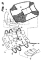
- Back member 12 has a recessed portion 21 which defines a cavity for receiving a support pad 43 which mounts treatment head module 20 (see FIG. 2).
- Transducer head module is connected to an interface cable 18 which is connected to a main operating unit 16.
- Main operating unit 16 supplies the control signals and power to operate treatment head module 20.
- Treatment head module 20 may have a pad 30 mounted on it or have a pad 30 independent of treatment head module.
- Pad 30 contains ultrasonic conductive material, preferably conductive gel for propagating ultrasound waves into the patient.
- Back member 12 is adjustably configured with respect to front member 14 by a securing means 22.
- Securing means 22 may include a plurality of belts 24 mounted on back member 12. Each belt 24 has a snap 26 which is received in a corresponding receptacle 28 located on rigid front member 14. Belt 24 is adjusted by a buckle 25.
- Back member 12 and front member 14 are lined by a padded back insert 32 and a padded front insert 34, respectively.
- Padded back insert 32 and padded front insert 34 add to the comfort of the patient when ultrasonic delivery system 10 is in use.
- Padded back insert 32 has an opening formed therethrough to allow pad 30 to contact the patients skin directly in the area of treatment.
- Padded back insert 32 and padded front insert 34 may be attached to the inside of back member 12 and front member 14, respectively using hook and loop pads 44 or other means known in the art.
- Back support 12 is contoured to the patient's body. Further, detachable side members 42 are installed to back member 12 to allow a better and more secure fit for the patient. Side members 42 are adjustable to allow ultrasonic deliver system 10 to be used by different sized patients. In one embodiment, side members 42 can be attached and adjusted using hook and loop pads 44. Recessed portion 21 may be configured with a support pad 43. Support pad 43 defines an opening for receiving treatment head module 20. The opening in support pad 43 is configured to allow adjustment of the location of treatment head module 20 over an injured area. The opening in padded back insert 32, the cavity defined in recessed portion 21 and pad 30 may all be dimensioned to allow for treatment head module 20 placement to be adjustable over a large area of the patient's body.
- front member 14 has an adjustment means 36 to configure the brace member 9 to a patient.
- Adjustment means 36 includes extended portions 40 located laterally on opposite sides of front member 14. Extended portions 40 have a hole therethrough for receiving an adjustable strap 38 for tightening and drawing the extended portions 40 inward toward the patient.
- reliefs 46 are supplied. Reliefs 46 prevent front member 14 from causing irritation of the patients abdomen due to an upper edge 39 of front member 14. Reliefs 46 are placed between front member 14 and padded front insert 34 at upper edge 39. If the patient leans forward while brace member 9 is in use, reliefs 46 engage the patient's abdomen first and act as a lever moving upper edge 39 away from the patient and hence protecting the patient from discomfort.
- FIGS. 4, 5 and 6 a patient is shown wearing brace member 9.
- FIGS. 4 and 5 illustrate the fit of brace member 9 on a patient.
- FIG. 6 shows a cross section of ultrasonic delivery system 10 in use. Recessed portion 21 of back member 12 receives support pad 43 which supports treatment head module 20. Treatment head module 20 propagates ultrasound waves into pad 30 which pass through skin 62 into spinal column 58 for healing vertebral body 60. Padded back insert 32 is shown defining an opening for pad 30.
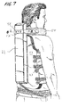
- FIGS. 7, 8 and 9 an alternate embodiment of ultrasonic delivery system 10 includes a configuration for treatment of the entire spinal column or a part thereof.
- FIG. 8 illustrates rigid back member 12 with recessed portion 21 extending the length of the patient's spinal column and forming a cavity. Further details are presented in FIG. 9. Recessed portion 21 adjacent to the patient's neck has a neck brace support 52 to secure neck brace 50 which can be attached with screws 48. Neck brace 50 and neck brace support 52 work in conjunction with securing means 22 to secure the patient's spinal column to prevent motion thereof.
- Backing pad 53 occupies vacant space within recessed area 21.
- Backing pad 43 defines an opening for the passage of cables 56, and further provides support for treatment head modules 20 to prevent them from backing away from the patients skin.
- a treatment head receptacle 54 holds a plurality of treatment head modules 20 adjacent to the patients spinal column. Treatment head receptacle 54 allows a doctor or technician to vertically or horizontally adjust treatment head modules 20 to locate them in appropriate positions to provide maximum effectiveness in accelerating the healing process.
- treatment head receptacle 54 is formed from a compressible material, for example, styrene foam. Treatment head receptacle 54 is compressed against backing pad 53 and treatment head modules 20 are pressed against the patient's skin. It is also contemplated that treatment head modules 20 have pads 30 installed thereon to propagate ultrasound waves into the patient. Pads 30 contain an ultrasound conducting material preferably conductive gel. Each treatment head 20 is placed over a different portion of the spinal column. Each treatment module can be activated with varying control signals. Parameters that can be controlled include durations of operation, frequencies of operation and/or power levels as required for individual patient treatment.
- a cross-section at the patients neck shows ultrasonic delivery system 10 during operation.
- Neck brace support 52 is shown mounted to recessed portion 21 of back member 12.
- Neck brace support may be attached to neck brace 52 by hook and loop or other attachment means known in the art.
- Backing pad 53 is secured within recessed portion 21 and supports treatment head module 20.
- Treatment head module 20 is also secured by treatment head receptacle 54.
- Treatment head module 20 is connected to pad 30 which is in contact with skin 62. Ultrasonic waves propagate from treatment head module 20 through pad 30 and skin 62 reaching spinal column 58 and accelerating healing in vertebral body 60.
Landscapes
- Health & Medical Sciences (AREA)
- Engineering & Computer Science (AREA)
- Biomedical Technology (AREA)
- Nuclear Medicine, Radiotherapy & Molecular Imaging (AREA)
- Radiology & Medical Imaging (AREA)
- Life Sciences & Earth Sciences (AREA)
- Animal Behavior & Ethology (AREA)
- General Health & Medical Sciences (AREA)
- Public Health (AREA)
- Veterinary Medicine (AREA)
- Surgical Instruments (AREA)
- Percussion Or Vibration Massage (AREA)
- Ultra Sonic Daignosis Equipment (AREA)
- Mechanical Treatment Of Semiconductor (AREA)
- Orthopedics, Nursing, And Contraception (AREA)
Claims (7)
- Ein Ultraschallabgabesystem, das Folgendes beinhaltet:ein Korsettelement (9), das einstellbar konfigurierbar ist, um einer menschlichen Wirbelsäule Halt zu geben, wobei das Korsettelement einen Hohlraum (21) definiert, der zum Anordnen anliegend an eine vorbestimmte Stelle, die über der menschlichen Wirbelsäule liegt, geeignet ist, und ein Rückenelement (12) beinhaltet, undeine Ultraschallerzeugungsanordung, die mindestens ein Behandlungskopfmodul (20) umfasst, das dimensioniert ist, um in dem Hohlraum (21) des Korsettelements positioniert zu werden, und eine Hauptbedieneinheit (16), um dem mindestens einen Behandlungskopfmodul Anregungssignale bereitzustellen, dadurch gekennzeichnet, dass das Korsettelement unbiegsam ist und ein unbiegsames Vorderelement (14) beinhaltet.
- Ultraschallabgabesystem gemäß Anspruch 1, wobei das Korsettelement (9) ferner einen gepolsterten Einsatz (32, 34) beinhaltet.
- Ultraschallabgabesystem gemäß Anspruch 1, wobei das Korsettelement ferner ein Behandlungskopfbehältnis für die einstellbare Positionierung des mindestens einen Behandlungskopfmoduls (20) beinhaltet.
- Ultraschallabgabesystem gemäß Anspruch 1, das ferner ein Polster (30) zum Leiten von Ultraschallwellen, die auf dem mindestens einen Behandlungskopfmodul angeordnet sind, beinhaltet.
- Ultraschallabgabesystem gemäß Anspruch 3, wobei das Behandlungskopfbehältnis innerhalb des Hohlraums (21) angeordnet ist, wobei das Behandlungskopfmodul dimensioniert ist, um einstellbar innerhalb des Behandlungskopfbehältnisses positioniert zu werden, und ein Polster (30) auf dem mindestens einen Behandlungskopfmodul angeordnet ist.
- Ultraschallabgabesystem gemäß Anspruch 5, wobei das Rückenelement (12) den Hohlraum (21) definiert, ein Paar Seitenelemente (42) einstellbar auf entweder dem Vorderelement (14) oder dem Rückenelement (12) montiert ist, ein gepolsterter Vordereinsatz (34) und ein gepolsterter Rückeneinsatz (32) jeweils mit dem Vorderelement (14) und dem Rückenelement (12) gekoppelt sind, wobei das gepolsterte Rückenelement (12) eine Öffung bildet, und das Polster ein Gel-Polster (30) beinhaltet, das durch die Öffnung in dem gepolsterten Rückeneinsatz (32) verläuft.
- Ultraschallabgabesystem gemäß einem der Ansprüche 1 bis 6, wobei das mindestens eine Behandlungskopfmodul eine Vielzahl von Behandlungskopfmodulen ist, die angepasst sind, um variierende Steuersignale zu empfangen.
Applications Claiming Priority (3)
| Application Number | Priority Date | Filing Date | Title |
|---|---|---|---|
| US6163097P | 1997-10-09 | 1997-10-09 | |
| US61630P | 1997-10-09 | ||
| PCT/US1998/021366 WO1999019025A1 (en) | 1997-10-09 | 1998-10-09 | Ultrasonic delivery system |
Publications (2)
| Publication Number | Publication Date |
|---|---|
| EP1019149A1 EP1019149A1 (de) | 2000-07-19 |
| EP1019149B1 true EP1019149B1 (de) | 2004-09-22 |
Family
ID=22037057
Family Applications (1)
| Application Number | Title | Priority Date | Filing Date |
|---|---|---|---|
| EP98951027A Expired - Lifetime EP1019149B1 (de) | 1997-10-09 | 1998-10-09 | Ultraschallabgabevorrichtung |
Country Status (8)
| Country | Link |
|---|---|
| EP (1) | EP1019149B1 (de) |
| AT (1) | ATE276797T1 (de) |
| AU (1) | AU757417B2 (de) |
| CA (1) | CA2311484A1 (de) |
| DE (1) | DE69826501T2 (de) |
| ES (1) | ES2229540T3 (de) |
| NZ (1) | NZ504411A (de) |
| WO (1) | WO1999019025A1 (de) |
Families Citing this family (20)
| Publication number | Priority date | Publication date | Assignee | Title |
|---|---|---|---|---|
| EP1465701A4 (de) | 2002-01-15 | 2008-08-13 | Univ California | System und verfahren zur direktionalen ultraschalltherapie an gelenkigen verbindungen |
| EP1503685B1 (de) | 2002-01-23 | 2012-10-31 | The Regents of The University of California | Implantierbares thermisches behandlungsgerät |
| US7258690B2 (en) | 2003-03-28 | 2007-08-21 | Relievant Medsystems, Inc. | Windowed thermal ablation probe |
| US8361067B2 (en) | 2002-09-30 | 2013-01-29 | Relievant Medsystems, Inc. | Methods of therapeutically heating a vertebral body to treat back pain |
| US8613744B2 (en) | 2002-09-30 | 2013-12-24 | Relievant Medsystems, Inc. | Systems and methods for navigating an instrument through bone |
| US8808284B2 (en) | 2008-09-26 | 2014-08-19 | Relievant Medsystems, Inc. | Systems for navigating an instrument through bone |
| US6907884B2 (en) | 2002-09-30 | 2005-06-21 | Depay Acromed, Inc. | Method of straddling an intraosseous nerve |
| US8088084B2 (en) | 2007-03-06 | 2012-01-03 | The Cleveland Clinic Foundation | Method and apparatus for repair of intervertebral discs |
| CN101396280A (zh) * | 2007-09-27 | 2009-04-01 | 重庆融海超声医学工程研究中心有限公司 | 一种超声治疗肠道推挤装置 |
| US10028753B2 (en) | 2008-09-26 | 2018-07-24 | Relievant Medsystems, Inc. | Spine treatment kits |
| JP5688022B2 (ja) | 2008-09-26 | 2015-03-25 | リリーバント メドシステムズ、インコーポレイテッド | 骨の内部を通って器具を誘導するためのシステムおよび方法 |
| US10390877B2 (en) | 2011-12-30 | 2019-08-27 | Relievant Medsystems, Inc. | Systems and methods for treating back pain |
| US10588691B2 (en) | 2012-09-12 | 2020-03-17 | Relievant Medsystems, Inc. | Radiofrequency ablation of tissue within a vertebral body |
| AU2013337680B2 (en) | 2012-11-05 | 2019-04-18 | Relievant Medsystems, Inc. | Systems and methods for creating curved paths through bone and modulating nerves within the bone |
| US9724151B2 (en) | 2013-08-08 | 2017-08-08 | Relievant Medsystems, Inc. | Modulating nerves within bone using bone fasteners |
| WO2021050767A1 (en) | 2019-09-12 | 2021-03-18 | Relievant Medsystems, Inc. | Systems and methods for tissue modulation |
| AU2021306313A1 (en) | 2020-07-10 | 2023-03-02 | Relievant Medsystems, Inc. | Vertebral denervation in conjunction with vertebral fusion |
| US12082876B1 (en) | 2020-09-28 | 2024-09-10 | Relievant Medsystems, Inc. | Introducer drill |
| EP4268150A4 (de) | 2020-12-22 | 2024-12-18 | Relievant Medsystems, Inc. | Vorhersage von kandidaten für die spinale neuromodulation |
| US12433668B1 (en) | 2021-11-08 | 2025-10-07 | Relievant Medsystems, Inc. | Impedance stoppage mitigation during radiofrequency tissue ablation procedures |
Family Cites Families (6)
| Publication number | Priority date | Publication date | Assignee | Title |
|---|---|---|---|---|
| BR8107560A (pt) | 1981-11-19 | 1983-07-05 | Luiz Romariz Duarte | Estimulacao ultra-sonica da consolidacao de fraturas osseas |
| US5186162A (en) | 1988-09-14 | 1993-02-16 | Interpore Orthopaedics, Inc. | Ultrasonic transducer device for treatment of living tissue and/or cells |
| US5211160A (en) | 1988-09-14 | 1993-05-18 | Interpore Orthopaedics, Inc. | Ultrasonic orthopedic treatment head and body-mounting means therefor |
| US5003965A (en) | 1988-09-14 | 1991-04-02 | Meditron Corporation | Medical device for ultrasonic treatment of living tissue and/or cells |
| IT1274590B (it) * | 1994-08-05 | 1997-07-18 | Ambrogio Lazzari | Apparecchiatura multifunzionale per trattamenti estetici |
| US5762616A (en) * | 1996-03-15 | 1998-06-09 | Exogen, Inc. | Apparatus for ultrasonic treatment of sites corresponding to the torso |
-
1998
- 1998-10-09 WO PCT/US1998/021366 patent/WO1999019025A1/en not_active Ceased
- 1998-10-09 AU AU96925/98A patent/AU757417B2/en not_active Ceased
- 1998-10-09 AT AT98951027T patent/ATE276797T1/de not_active IP Right Cessation
- 1998-10-09 EP EP98951027A patent/EP1019149B1/de not_active Expired - Lifetime
- 1998-10-09 CA CA002311484A patent/CA2311484A1/en not_active Abandoned
- 1998-10-09 DE DE69826501T patent/DE69826501T2/de not_active Expired - Fee Related
- 1998-10-09 NZ NZ504411A patent/NZ504411A/xx unknown
- 1998-10-09 ES ES98951027T patent/ES2229540T3/es not_active Expired - Lifetime
Also Published As
| Publication number | Publication date |
|---|---|
| EP1019149A1 (de) | 2000-07-19 |
| AU9692598A (en) | 1999-05-03 |
| ATE276797T1 (de) | 2004-10-15 |
| NZ504411A (en) | 2003-02-28 |
| CA2311484A1 (en) | 1999-04-22 |
| DE69826501T2 (de) | 2005-09-29 |
| WO1999019025A1 (en) | 1999-04-22 |
| DE69826501D1 (de) | 2004-10-28 |
| AU757417B2 (en) | 2003-02-20 |
| ES2229540T3 (es) | 2005-04-16 |
Similar Documents
| Publication | Publication Date | Title |
|---|---|---|
| AU757417B2 (en) | Ultrasonic delivery system | |
| CN1178716C (zh) | 用超声波治疗人体各部位的装置 | |
| AU740696B2 (en) | Submersible system for ultrasonic treatment | |
| EP1180056B1 (de) | Gerät zur ultraschallbehandlung von reflexsympathischer dystrophie | |
| EP1064052B1 (de) | Gerät und methode zur befestigung eines ultraschallwandlers | |
| KR20010006563A (ko) | 초음파 골질 요법용 장치 | |
| US20040064051A1 (en) | Ultrasound transducer coupling apparatus | |
| US6406443B1 (en) | Self-contained ultrasound applicator | |
| AU752098B2 (en) | Method and apparatus for ultrasonic treatment of carpal tunnel syndrome | |
| AU768476B2 (en) | Self-contained ultrasound applicator | |
| MXPA97006154A (en) | Apparatus for ultrasonic treatment of the hu |
Legal Events
| Date | Code | Title | Description |
|---|---|---|---|
| PUAI | Public reference made under article 153(3) epc to a published international application that has entered the european phase |
Free format text: ORIGINAL CODE: 0009012 |
|
| 17P | Request for examination filed |
Effective date: 20000509 |
|
| AK | Designated contracting states |
Kind code of ref document: A1 Designated state(s): AT BE CH CY DE DK ES FI FR GB GR IE IT LI LU MC NL PT SE |
|
| 17Q | First examination report despatched |
Effective date: 20030701 |
|
| GRAP | Despatch of communication of intention to grant a patent |
Free format text: ORIGINAL CODE: EPIDOSNIGR1 |
|
| GRAS | Grant fee paid |
Free format text: ORIGINAL CODE: EPIDOSNIGR3 |
|
| GRAA | (expected) grant |
Free format text: ORIGINAL CODE: 0009210 |
|
| RAP1 | Party data changed (applicant data changed or rights of an application transferred) |
Owner name: EXOGEN, INC. |
|
| AK | Designated contracting states |
Kind code of ref document: B1 Designated state(s): AT BE CH CY DE DK ES FI FR GB GR IE IT LI LU MC NL PT SE |
|
| PG25 | Lapsed in a contracting state [announced via postgrant information from national office to epo] |
Ref country code: FI Free format text: LAPSE BECAUSE OF FAILURE TO SUBMIT A TRANSLATION OF THE DESCRIPTION OR TO PAY THE FEE WITHIN THE PRESCRIBED TIME-LIMIT Effective date: 20040922 Ref country code: CY Free format text: LAPSE BECAUSE OF FAILURE TO SUBMIT A TRANSLATION OF THE DESCRIPTION OR TO PAY THE FEE WITHIN THE PRESCRIBED TIME-LIMIT Effective date: 20040922 |
|
| REG | Reference to a national code |
Ref country code: GB Ref legal event code: FG4D |
|
| REG | Reference to a national code |
Ref country code: CH Ref legal event code: EP |
|
| PG25 | Lapsed in a contracting state [announced via postgrant information from national office to epo] |
Ref country code: LU Free format text: LAPSE BECAUSE OF NON-PAYMENT OF DUE FEES Effective date: 20041009 |
|
| REG | Reference to a national code |
Ref country code: IE Ref legal event code: FG4D |
|
| REF | Corresponds to: |
Ref document number: 69826501 Country of ref document: DE Date of ref document: 20041028 Kind code of ref document: P |
|
| PG25 | Lapsed in a contracting state [announced via postgrant information from national office to epo] |
Ref country code: MC Free format text: LAPSE BECAUSE OF NON-PAYMENT OF DUE FEES Effective date: 20041031 |
|
| PG25 | Lapsed in a contracting state [announced via postgrant information from national office to epo] |
Ref country code: DK Free format text: LAPSE BECAUSE OF FAILURE TO SUBMIT A TRANSLATION OF THE DESCRIPTION OR TO PAY THE FEE WITHIN THE PRESCRIBED TIME-LIMIT Effective date: 20041222 |
|
| REG | Reference to a national code |
Ref country code: SE Ref legal event code: TRGR Ref country code: GR Ref legal event code: EP Ref document number: 20040404171 Country of ref document: GR |
|
| REG | Reference to a national code |
Ref country code: ES Ref legal event code: FG2A Ref document number: 2229540 Country of ref document: ES Kind code of ref document: T3 |
|
| ET | Fr: translation filed | ||
| PLBE | No opposition filed within time limit |
Free format text: ORIGINAL CODE: 0009261 |
|
| STAA | Information on the status of an ep patent application or granted ep patent |
Free format text: STATUS: NO OPPOSITION FILED WITHIN TIME LIMIT |
|
| PGFP | Annual fee paid to national office [announced via postgrant information from national office to epo] |
Ref country code: GR Payment date: 20050913 Year of fee payment: 8 |
|
| 26N | No opposition filed |
Effective date: 20050623 |
|
| PGFP | Annual fee paid to national office [announced via postgrant information from national office to epo] |
Ref country code: NL Payment date: 20051003 Year of fee payment: 8 |
|
| PGFP | Annual fee paid to national office [announced via postgrant information from national office to epo] |
Ref country code: GB Payment date: 20051005 Year of fee payment: 8 Ref country code: SE Payment date: 20051005 Year of fee payment: 8 |
|
| PGFP | Annual fee paid to national office [announced via postgrant information from national office to epo] |
Ref country code: DE Payment date: 20051006 Year of fee payment: 8 |
|
| PGFP | Annual fee paid to national office [announced via postgrant information from national office to epo] |
Ref country code: FR Payment date: 20051010 Year of fee payment: 8 |
|
| PGFP | Annual fee paid to national office [announced via postgrant information from national office to epo] |
Ref country code: IE Payment date: 20051012 Year of fee payment: 8 Ref country code: AT Payment date: 20051012 Year of fee payment: 8 |
|
| PGFP | Annual fee paid to national office [announced via postgrant information from national office to epo] |
Ref country code: CH Payment date: 20051014 Year of fee payment: 8 |
|
| PGFP | Annual fee paid to national office [announced via postgrant information from national office to epo] |
Ref country code: ES Payment date: 20051129 Year of fee payment: 8 |
|
| PGFP | Annual fee paid to national office [announced via postgrant information from national office to epo] |
Ref country code: BE Payment date: 20051215 Year of fee payment: 8 |
|
| PG25 | Lapsed in a contracting state [announced via postgrant information from national office to epo] |
Ref country code: IE Free format text: LAPSE BECAUSE OF NON-PAYMENT OF DUE FEES Effective date: 20061009 Ref country code: AT Free format text: LAPSE BECAUSE OF NON-PAYMENT OF DUE FEES Effective date: 20061009 |
|
| PG25 | Lapsed in a contracting state [announced via postgrant information from national office to epo] |
Ref country code: SE Free format text: LAPSE BECAUSE OF NON-PAYMENT OF DUE FEES Effective date: 20061010 |
|
| PG25 | Lapsed in a contracting state [announced via postgrant information from national office to epo] |
Ref country code: LI Free format text: LAPSE BECAUSE OF NON-PAYMENT OF DUE FEES Effective date: 20061031 Ref country code: CH Free format text: LAPSE BECAUSE OF NON-PAYMENT OF DUE FEES Effective date: 20061031 |
|
| PG25 | Lapsed in a contracting state [announced via postgrant information from national office to epo] |
Ref country code: NL Free format text: LAPSE BECAUSE OF NON-PAYMENT OF DUE FEES Effective date: 20070501 Ref country code: DE Free format text: LAPSE BECAUSE OF NON-PAYMENT OF DUE FEES Effective date: 20070501 |
|
| REG | Reference to a national code |
Ref country code: CH Ref legal event code: PL |
|
| EUG | Se: european patent has lapsed | ||
| GBPC | Gb: european patent ceased through non-payment of renewal fee |
Effective date: 20061009 |
|
| NLV4 | Nl: lapsed or anulled due to non-payment of the annual fee |
Effective date: 20070501 |
|
| REG | Reference to a national code |
Ref country code: IE Ref legal event code: MM4A |
|
| REG | Reference to a national code |
Ref country code: FR Ref legal event code: ST Effective date: 20070629 |
|
| PG25 | Lapsed in a contracting state [announced via postgrant information from national office to epo] |
Ref country code: GB Free format text: LAPSE BECAUSE OF NON-PAYMENT OF DUE FEES Effective date: 20061009 |
|
| BERE | Be: lapsed |
Owner name: *EXOGEN INC. Effective date: 20061031 |
|
| PG25 | Lapsed in a contracting state [announced via postgrant information from national office to epo] |
Ref country code: PT Free format text: LAPSE BECAUSE OF NON-PAYMENT OF DUE FEES Effective date: 20050222 |
|
| REG | Reference to a national code |
Ref country code: ES Ref legal event code: FD2A Effective date: 20061010 |
|
| PG25 | Lapsed in a contracting state [announced via postgrant information from national office to epo] |
Ref country code: FR Free format text: LAPSE BECAUSE OF NON-PAYMENT OF DUE FEES Effective date: 20061031 Ref country code: ES Free format text: LAPSE BECAUSE OF NON-PAYMENT OF DUE FEES Effective date: 20061010 |
|
| PG25 | Lapsed in a contracting state [announced via postgrant information from national office to epo] |
Ref country code: GR Free format text: LAPSE BECAUSE OF NON-PAYMENT OF DUE FEES Effective date: 20070503 |
|
| PGFP | Annual fee paid to national office [announced via postgrant information from national office to epo] |
Ref country code: IT Payment date: 20081029 Year of fee payment: 11 |
|
| PG25 | Lapsed in a contracting state [announced via postgrant information from national office to epo] |
Ref country code: BE Free format text: LAPSE BECAUSE OF FAILURE TO SUBMIT A TRANSLATION OF THE DESCRIPTION OR TO PAY THE FEE WITHIN THE PRESCRIBED TIME-LIMIT Effective date: 20061031 |
|
| PG25 | Lapsed in a contracting state [announced via postgrant information from national office to epo] |
Ref country code: IT Free format text: LAPSE BECAUSE OF NON-PAYMENT OF DUE FEES Effective date: 20091009 |