EP1019664B1 - Elektrolichtbogen mit einer kühlvorrichtung enthaltend panele - Google Patents
Elektrolichtbogen mit einer kühlvorrichtung enthaltend panele Download PDFInfo
- Publication number
- EP1019664B1 EP1019664B1 EP98939788A EP98939788A EP1019664B1 EP 1019664 B1 EP1019664 B1 EP 1019664B1 EP 98939788 A EP98939788 A EP 98939788A EP 98939788 A EP98939788 A EP 98939788A EP 1019664 B1 EP1019664 B1 EP 1019664B1
- Authority
- EP
- European Patent Office
- Prior art keywords
- tubes
- furnace
- electric arc
- layer
- arc furnace
- Prior art date
- Legal status (The legal status is an assumption and is not a legal conclusion. Google has not performed a legal analysis and makes no representation as to the accuracy of the status listed.)
- Expired - Lifetime
Links
Images


Classifications
-
- F—MECHANICAL ENGINEERING; LIGHTING; HEATING; WEAPONS; BLASTING
- F27—FURNACES; KILNS; OVENS; RETORTS
- F27D—DETAILS OR ACCESSORIES OF FURNACES, KILNS, OVENS OR RETORTS, IN SO FAR AS THEY ARE OF KINDS OCCURRING IN MORE THAN ONE KIND OF FURNACE
- F27D1/00—Casings; Linings; Walls; Roofs
- F27D1/12—Casings; Linings; Walls; Roofs incorporating cooling arrangements
-
- F—MECHANICAL ENGINEERING; LIGHTING; HEATING; WEAPONS; BLASTING
- F27—FURNACES; KILNS; OVENS; RETORTS
- F27B—FURNACES, KILNS, OVENS OR RETORTS IN GENERAL; OPEN SINTERING OR LIKE APPARATUS
- F27B3/00—Hearth-type furnaces, e.g. of reverberatory type; Electric arc furnaces ; Tank furnaces
- F27B3/10—Details, accessories or equipment, e.g. dust-collectors, specially adapted for hearth-type furnaces
- F27B3/24—Cooling arrangements
-
- F—MECHANICAL ENGINEERING; LIGHTING; HEATING; WEAPONS; BLASTING
- F27—FURNACES; KILNS; OVENS; RETORTS
- F27D—DETAILS OR ACCESSORIES OF FURNACES, KILNS, OVENS OR RETORTS, IN SO FAR AS THEY ARE OF KINDS OCCURRING IN MORE THAN ONE KIND OF FURNACE
- F27D1/00—Casings; Linings; Walls; Roofs
- F27D1/18—Door frames; Doors, lids or removable covers
- F27D1/1808—Removable covers
- F27D1/1816—Removable covers specially adapted for arc furnaces
-
- Y—GENERAL TAGGING OF NEW TECHNOLOGICAL DEVELOPMENTS; GENERAL TAGGING OF CROSS-SECTIONAL TECHNOLOGIES SPANNING OVER SEVERAL SECTIONS OF THE IPC; TECHNICAL SUBJECTS COVERED BY FORMER USPC CROSS-REFERENCE ART COLLECTIONS [XRACs] AND DIGESTS
- Y02—TECHNOLOGIES OR APPLICATIONS FOR MITIGATION OR ADAPTATION AGAINST CLIMATE CHANGE
- Y02P—CLIMATE CHANGE MITIGATION TECHNOLOGIES IN THE PRODUCTION OR PROCESSING OF GOODS
- Y02P10/00—Technologies related to metal processing
- Y02P10/20—Recycling
Definitions
- This invention concerns an electric arc furnace with a cooling device with panels as set forth in the main claim.
- the cooling device with panels is applied in cooperation with the sidewalls and upper walls and with the roof of the electric arc furnace.
- the state of the art includes the structure of electric furnaces, particularly electric arc furnaces, which comprise a refractory lower shell, incorporating the hearth, above which there is the upper shell which functions as a sidewall where the cooling panels are positioned.
- Such furnaces also include a cover consisting of a roof which is also cooled.
- the sidewall of the furnace is defined by a row of these panels arranged substantially in correspondence with the outer edge of the lower shell; this situation makes possible the at least partial formation of a layer of slag, which attaches itself on the front part of the panels.
- this layer of slag is not normally enough to protect the refractory material from the thermal and chemical stresses which can be found in electric arc furnaces which are currently used.
- This layer of slag has an insulating function so as to reduce the flow of heat and therefore to preserve the cooling panels from premature wear.
- the low resistance is caused on the one hand by the fact that only a very thin layer of slag attaches itself to the panels, and this is not sufficient to preserve the panels from the risk of breaking; and on the other hand by the great number of welds, each of which constitutes a critical point in the panels.
- the panel structures are dangerous to use because, due to the rigid construction of the panels and the great number of welds, the tubes are subject to breakages and there is therefore a danger of water leaking out.
- GB-A-2.270.146 shows an electric furnace with lateral cooling panels located above the lower shell and with cooling tubes which act on the refractory zone of the lower shell.
- DE-C-4223109 shows panels with a plurality of horizontal mono-tubes arranged in two parallel rows and separated at regular intervals.
- EP-A-0699885 shows a cooling system for the upper edge of the refractory part of the furnace.
- This system includes U-shaped cooled tubes with the vertical tubes facing towards the bath of liquid metal.
- This embodiment entails a variety of problems, on the one hand because the continuous tubes become unusable in the event of a breakage, and on the other hand because they are easily subject to perforations, since they face the bath of liquid metal.
- FR-A-2.486.863 does not solve any of the above-mentioned problems, as there are no spaces whatsoever between the tubes which would allow a thick, consistent layer of slag to form.
- the purpose of the invention is to achieve a cooling device with panels which enables the insulation properties of the layer of slag to be exploited in the most efficient manner, thus preserving the panels from progressive consumption and wear and therefore greatly increasing their working life and efficiency.
- a further purpose of the invention is to achieve a cooling device with panels for electric arc furnaces which will greatly reduce the progressive wear of the refractory material at the upper circular strip of the lower shell.
- Yet another purpose of the invention is to obtain a cooling device in which the welds are reduced to a minimum and thus the critical points along the hydraulic circuit are also reduced to a minimum; therefore, the possibility of breakdowns and cracking of the device is reduced, which thus increases the resistance of the panels to the thermo-mechanical stresses which occur during the functioning of the furnace.
- the cooling device comprises at least three substantially concentric levels or layers of cooling tubes, arranged one in front of the other and organised as panels, each one covering a circular sector of the furnace.
- the distance, or pitch, between the rows of these levels or layers of tubes, in the direction of the vertical section of the furnace, increases as the rows go from the outside towards the inside of the furnace.
- the tubes of the outer layer are closer to each other so as to make a substantially continuous wall; the tubes of the intermediate layer are farther apart with the rows of tubes at a greater distance from each other; and the tubes of the inner layer are even farther apart so as to define wide spaces between the superimposed rows of tubes.
- the tubes of the outer layer are not in contact but are separated by fissures.
- a continuous wall which acts as a containing and supporting cover for the panels of cooling tubes.
- the inner layer of tubes is sloping, along the height of the furnace, with respect to the other two layers.
- this inclination of the inner layer affects only the lower part thereof.
- the wide fissures and spaces between the tubes of the inner layer and the intermediate layer allow the slag to deposit in a thick layer, which protects and insulates the tubes thermally, increases their resistance and preserves them from the thermo-mechanical stresses and from the corrosive effects caused by the chemical reactions which occur inside the furnace.
- the layer of tubes which most contributes to the heat exchange with the inner area of the furnace is the inner layer, while the intermediate and outer layers are at least partly heat insulated from the working area of the furnace, and are thus protected and preserved from progressive wear.
- This configuration of the panels also ensures a smaller energy loss, inasmuch as the layer most affected by heat exchange with the working area of the furnace is the inner layer, where the density of tubes is least.
- the heat accumulated by the thick layer of slag during the melting process is yielded to the scrap during the subsequent melting cycle, which saves energy and speeds up the melting times.
- the accumulation of heat ensured by the layer of slag reduces the heat shock during the cooling steps of the furnace and/or when the roof is opened, and therefore minimises the thermo-mechanical stresses on the metallic tubes.
- At least the inner layer is supplied with cooling liquid independently of the other two layers so that, even in the event of a breakage or accident, the inner layer can continue to carry out its function as an anchorage element for the slag, in order to form an insulating and protective layer for the outer layers.
- the three layers are all supplied independently of each other.
- the configuration of the panels according to the invention also facilitates maintenance; this is because the inner layer which, since it is exposed to the working area of the furnace, is most in need of restoration operations and possibly the replacement of worn parts, has wide spaces between the tubes which facilitate and assist such operations.
- the tubes of at least the inner layer are equipped, according to a variant, with elements to attach the slag, such as for example metallic hooks, or cooled rings, made of material with a high thermal conductivity.
- the layers may also be connected to each other by means of attachment, connection and reciprocal positioning hooks, possibly made with two metals so as to increase both thermal and mechanical resistance.
- connection hooks are cooled internally by a circulating cooling liquid.
- the tubes used are of the unwelded type, for example obtained by hot bending, which considerably reduces the critical points which are most subject to thermal stress, and therefore considerably increases the working life of the panels.
- the tubes of the panels may be of a non-circular section, according to a variant, in order to optimise the coefficient of heat exchange by adjusting the speed of the water and reducing the overall rate of flow by making water circulate only in the part of the tube exposed to the thermal flow.
- the part of the tube where there is no water circulating may be filled with an appropriate material or fluid, or may be left empty.
- the roof of the furnace is also cooled with a device with at least three layers of cooling tubes where the layers facing towards the inside of the furnace have a progressively greater pitch so as to define progressively larger spaces wherein the slag, powders or otherwise may become attached and consolidated.
- the pitch of the layers may be constant for the entire diameter of the furnace, or may be variable in order to adjust the capacity to remove the thermal flow according to where the hotter or cooler areas of the furnace are.
- the water is made to flow under inspiration and not under pressure, so that it is easy to stop the flow of water and minimise leakages in the event of a break in the tubes.
- These tubes are inserted into the refractory material of the lower shell and extend for a certain segment inside the working area of the furnace at a desired height with respect to the upper level of the liquid metal.
- This protruding part of the cooling tubes causes an extension to the cooled area which affects the entire upper edge of the lower shell made of refractory material, with a consequent thermal protection of the zone which is most subject to stress and wear due to the high temperatures and the chemical reactions which occur there.
- the protruding part of the tubes is sprayed with refractory material which creates a protective covering layer which mechanically protects and thermally insulates that part of the tubes which protrudes inside the furnace.
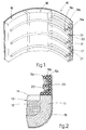
- the electric furnace partly shown in the attached Figures comprises a lower shell 11 made of a refractory material and acting as a container for the bath of melting metal 12.
- the bath of melting metal 12 has an upper level 13 above which there is a layer of slag 14.
- the lower shell 11 cooperates on its outer part with a containing and supporting element 15 made of metal.
- the furnace comprises an upper shell defined by a plurality of cooling panels 16 comprising adjacent tubes 17 inside which the cooling liquid circulates.
- the circular upper shell is covered at the top by a roof 18 associated with a relative cooling device 10 with panels 16.
- the cooling device 10 also comprises a panel, or portion of a panel 16, consisting of layers of tubes 17 located one in front of the other from the outside to the inside of the furnace; in this case, there is an outer layer 19a, an intermediate layer 19b and an inner layer 19c.
- the tubes 17 are arranged substantially horizontally so as to follow the conformation of the walls of the furnace. In a variant which is not shown here the tubes 17 are substantially vertical.
- the outer layer 19a cooperates on the outer part with a metallic wall 20 acting as a supporting and containing element.
- the tubes 17 are near each other so as to define a substantially continuous wall although there are fissures 21 between one tube 17 and the next.
- the fissures 21 increase the resistance of the tubes 17 to the thermo-mechanical stresses which occur during the working cycle.
- the tubes 17 are farther apart so that, in this case, for each row of the intermediate layer 19b there are two rows of the outer layer 19a.
- the tubes are even farther apart so that, in this case, for each row of the inner layer 19c there are two rows of the intermediate layer 19b.
- the spaces between the cooling tubes 17 of the inner layer 19c facilitate the formation of a thick layer of slag 22 which, as it becomes attached to the tubes 17, covers them and protects them from wear.
- This thick layer of slag 22 which forms between the tubes 17 of the inner layer 19c also functions as a heat accumulator, since it accumulates heat which it then gives up to the scrap at the start of a new melting cycle.
- the layer of slag 22 insulates and protects the intermediate layer 19b and the outer layer 19a both from thermo-mechanical stresses caused by the extremely high temperatures and also from the chemical reactions which occur inside the furnace, particularly in the area immediately above the layer of slag 14.
- all or part of the inner layer 19c is sloping with respect to the other two layers 19a, 19b.
- Fig. 3 shows a panel with tubes 17a sloping downwards and outwards and protruding for a certain segment inside the area of the furnace above the liquid bath 12.
- the end of the cooling tubes 17a protrudes inside the area of the furnace to a value of "m”, from the outer wall 20, by about 450 ⁇ 600 mm, with a distance "n” from the inner edge of the lower shell 11 of about 100 ⁇ 150 mm.
- the height "1" of the end of the cooling tube 17a with respect to the upper level of the liquid bath 12 has a value of about 400 ⁇ 500 mm.
- the cooling tubes 17a sloping and protruding towards the inside of the working area of the furnace, allow a layer of slag 22a to form which covers the shoulder 11a of the lower shell 11 in the zone where there is the greatest risk of wear and where the thermo-mechanical stresses are highest due to the high temperatures and the chemical reactions.
- the protruding part of the tubes 17a is sprayed with refractory material so that the refractory, cooling down as it comes into contact with the tubes 17a, solidifies and creates a protective and insulating layer which is then incorporated into the slag 22a which is progressively deposited during the melting cycle onto the tubes 17a.
- the water is discharged far from the furnace. Moreover, to farther facilitate the discharge of the water, the water is supplied to the tubes 17, 17a by suction and not under pressure.
- the inner layer 19c is supplied with water independently of the other two layers 19a and 19b so that, even in the event of a breakage, it can continue to carry out its function of forming the layer of protective and insulating slag, and the furnace can continue to function.
- the inner layer 19c is supplied independently while the other two layers 19a and 19b are supplied in series; in Fig. 6b the three layers 19a, 19b and 19c are all supplied independently.
- the layers 19a, 19b and 19c are connected to each other by means of hooks 23 for example made of hollow tubes so as to allow the cooling liquid to circulate; they are not shown in detail here.
- the tubes 17 On their surface the tubes 17 have means which facilitate and consolidate the attachment of the slag 22. These means may consist of parallelepiped protrusions 24 distributed on the periphery of the tube 17 and arranged in alignment (Fig. 7a) or like a chess board (Fig. 7b).
- These means may also consist of longitudinal ridges 124 which run continuously along the whole length of the tube 17; they may be circular in section, as in Fig. 7c, square, hexagonal or any other desired section.
- the means may consist of hooks 224 which extend in a transverse direction with respect to the relative tube 17.
- the tubes 17 used, according to the invention have no welds and may be of different shapes, not only circular; for example they may be oval or similar, or they may contain filling means inside which limit the area of transit of the cooling liquid, and concentrate it in the front area which faces the inside of the furnace.
- Figs. 4 and 5 the device 10 is applied to the roof 18 of the furnace which has a hole 18a substantially at the centre, through which the electrode 25 is inserted.
- the device 10 includes, as above, an outer layer 19a, an intermediate layer 19b and an inner layer 19c facing the working area of the furnace.
- the tubes 17 of the layers 19a, 19b and 19c may be arranged along concentric circumferences with respect to the roof 18 (Fig. 4), or radially (Fig. 5). In Figs. 4 and 5 it is possible to see the connecting hooks 26 by means of which the layers 19a, 19b and 19c are constrained together.
- the tubes 17 are associated with manifolds 27, 28 for the inlet-outlet of the cooling liquid.
- the spaces between the tubes 17 increase in size as they go towards the inner part of the furnace in order to facilitate the attachment of the slag 22 so as to create a protective and insulating layer for the inner layers.
Landscapes
- Engineering & Computer Science (AREA)
- Mechanical Engineering (AREA)
- General Engineering & Computer Science (AREA)
- Vertical, Hearth, Or Arc Furnaces (AREA)
- Furnace Housings, Linings, Walls, And Ceilings (AREA)
- Furnace Details (AREA)
- Electric Stoves And Ranges (AREA)
- Discharge Heating (AREA)
Claims (18)
- Elektrischer Lichtbogenofen mit einer unteren Ofenwanne (11), die ein Schmelzbad (12) enthält, und einer oberen Schale, die durch eine Mehrzahl von aus Kühlrohren (17) bestehenden Paneelen (16) gebildet wird, wobei die obere Schale durch ein Dach (18) bedeckt wird, wobei ferner die untere Schale (11) an ihrem äußeren Teil ein metallisches Aufnahmeelement (15) aufweist sowie die innere hitzebeständige Auskleidung eine obere Kante (11a) besitzt, die im Wesentlichen an der oberen Linie der oberhalb des Schmelzbades (12) befindlichen Schlackenschicht (14) angeordnet ist, dadurch gekennzeichnet, daß jedes Paneel (16) mindestens drei Schichten von Kühlrohren aufweist, nämlich eine äußere Schicht (19a), eine Zwischenschicht (19b) und eine innere Schicht (19c), wobei sich die Schichten der Kühlrohre vertikal entlang der vertikalen Seitenwand der oberen Schale oberhalb der hitzebeständigen Kante (I 1a) der Ofenwanne (11) erstrecken, ferner daß der vertikale Abstand zwischen den Kühlrohren (17) der Zwischenschicht (19b) größer ist als der vertikale Abstand zwischen den Kühlrohren (17) der äußeren Schicht (19a) und daß der vertikale Abstand zwischen den Kühlrohren (17) der inneren Schicht (19c) größer ist als der vertikale Abstand zwischen den Kühlrohren (17) der Zwischenschicht (19b), sodaß Spalte und Räume zunehmender Größe von der Außenseite des Ofens zu dessen Innenseite begrenzt werden, worin sich die Schlacke selbst befestigt.
- Elektrischer Lichtbogenofen nach Anspruch 1, bei dem im Zusammenwirken mit der oberen Kante (11a) der unteren Wanne (11) ein Paneel von Kühlrohren (17a) angeordnet ist, das mit dem oberen Spiegel der Schlacke (14) zusammenwirkt.
- Elektrischer Lichtbogenofen nach Anspruch 1 oder 2, bei dem dem Dach (18) des Ofens eine äußere Schicht (19a), eine Zwischenschicht (19b) und mindestens eine innere Schicht (19c) zugeordnet ist, wobei der Abstand der Rohre (17) jeder Schicht (19a, 19b, 19c) von der Außenseite des Ofens zu dessen Innenseite zunehmend größer wird.
- Elektrischer Lichtbogenofen nach Anspruch 2, bei dem die mit der oberen Kante (11a) der unteren Wanne (11) zusammenwirkenden Kühlrohre (17a) gegen die Außenseite des Ofens zu nach unten geneigt sind.
- Elektrischer Lichtbogenofen nach Anspruch 4, bei dem das vordere Ende der Rohre (17a) gegen die Innenseite des Ofens mit einem Abstand von mindestens 100mm in bezug auf die innere Kante der unteren Wanne (11) vorstehen.
- Elektrischer Lichtbogenofen nach Anspruch 4 oder 5, bei dem das vordere Ende der Rohre (17a) in einer Höhe von mindestens 400mm in bezug auf den Spiegel des Schmelzbades (12) angeordnet ist.
- Elektrischer Lichtbogenofen nach einem der vorstehenden Ansprüche, bei dem jener Teil der Rohre (17), der in den Arbeitsbereich des Ofens ragt, durch ein beim Start des Schmelzzyklus aufgesprühtes hitzebeständiges Material bedeckt ist.
- Elektrischer Lichtbogenofen nach einem der vorstehenden Ansprüche, bei dem jeder Reihe von Rohren (17) der inneren Schicht (19c) zwei Reihen von Rohren (17) der Zwischenschicht (19b) zugeordnet sind.
- Elektrischer Lichtbogenofen nach einem der vorstehenden Ansprüche, bei dem jeder Reihe von Rohren (17) der Zwischenschicht (19b) zwei Reihen von Rohren (17) der äußeren Schicht (19a) zugeordnet sind.
- Elektrischer Lichtbogenofen nach einem der vorstehenden Ansprüche, bei dem die Kühlrohre (17) der äußeren Schicht (19a) nahe aneinander angeordnet sind und voneinander durch Spalte (21) getrennt sind.
- Elektrischer Lichtbogenofen nach einem der vorstehenden Ansprüche, bei dem die äußere Schicht (19a) an ihrer Außenseite durch eine metallische Wand (20) bedeckt ist.
- Elektrischer Lichtbogenofen nach einem der vorstehenden Ansprüche, bei dem die innere Schicht (19c) mindestens teilweise gegenüber der Zwischenschicht (19b) und der äußeren Schicht (19a) geneigt ist.
- Elektrischer Lichtbogenofen nach einem der vorstehenden Ansprüche, bei dem mindestens die innere Schicht (19c) unabhängig von den anderen beiden Schichten (19a, 19b) mit Kühlflüssigkeit beliefert wird.
- Elektrischer Lichtbogenofen nach einem der vorstehenden Ansprüche, bei dem die Zwischenschicht (19b) und die äußere Schicht (19a) in Serie geschaltet sind.
- Elektrischer Lichtbogenofen nach einem der vorstehenden Ansprüche, bei dem mindestens die mit der oberen Kante (11a) der unteren Wanne (11) zusammenwirkenden Rohre (17a) durch Saugwirkung mit Kühlflüssigkeit beliefert werden.
- Elektrischer Lichtbogenofen nach einem der vorstehenden Ansprüche, bei dem die Schichten (19a, 19b, 19c) miteinander durch metallische Haken (26) verbunden sind.
- Elektrischer Lichtbogenofen nach einem der vorstehenden Ansprüche, bei dem mindestens die Rohre (17) der inneren Schicht (19c) Oberflächenmittel zum Befestigen bzw. Festhalten der Schlacke aufweisen, die der Länge nach in diskontinuierlicher Weise (24), der Länge nach in kontinuierlicher Weise (124) oder quer (224) angeordnet sind.
- Elektrischer Lichtbogenofen nach einem der vorstehenden Ansprüche, bei dem mindestens die innere Schicht (19c) aus einem kontinuierlichem Heißbiegerohr besteht.
Applications Claiming Priority (3)
| Application Number | Priority Date | Filing Date | Title |
|---|---|---|---|
| IT1997GO000018A IT1304334B1 (it) | 1997-09-10 | 1997-09-10 | Dispositivo di raffreddamento pannelli per forno elettricoad arco |
| ITGO970018 | 1997-09-10 | ||
| PCT/IB1998/001371 WO1999013281A1 (en) | 1997-09-10 | 1998-09-03 | Cooling device with panels for electric arc furnace |
Publications (2)
| Publication Number | Publication Date |
|---|---|
| EP1019664A1 EP1019664A1 (de) | 2000-07-19 |
| EP1019664B1 true EP1019664B1 (de) | 2001-12-12 |
Family
ID=11355470
Family Applications (1)
| Application Number | Title | Priority Date | Filing Date |
|---|---|---|---|
| EP98939788A Expired - Lifetime EP1019664B1 (de) | 1997-09-10 | 1998-09-03 | Elektrolichtbogen mit einer kühlvorrichtung enthaltend panele |
Country Status (8)
| Country | Link |
|---|---|
| US (1) | US6249538B1 (de) |
| EP (1) | EP1019664B1 (de) |
| AT (1) | ATE210810T1 (de) |
| AU (1) | AU8818798A (de) |
| DE (1) | DE69802953T2 (de) |
| ES (1) | ES2168786T3 (de) |
| IT (1) | IT1304334B1 (de) |
| WO (1) | WO1999013281A1 (de) |
Families Citing this family (8)
| Publication number | Priority date | Publication date | Assignee | Title |
|---|---|---|---|---|
| US6535522B1 (en) * | 1997-10-01 | 2003-03-18 | Globespanvirata, Inc. | Multiple protocol interface and method for use in a communications system |
| EP1469085A1 (de) * | 2003-04-14 | 2004-10-20 | Paul Wurth S.A. | Ofenwand mit Kühlplatten für einen metallurgischen Ofen |
| KR101159968B1 (ko) * | 2010-04-29 | 2012-06-25 | 현대제철 주식회사 | 전기로용 냉각 패널 |
| CN108613554B (zh) | 2013-12-20 | 2020-02-07 | 魁北克9282-3087公司(加钛顾问公司) | 用于冶金炉的炉盖 |
| US9696092B2 (en) * | 2014-07-16 | 2017-07-04 | CIX Inc. | Furnace cooling panel monitoring system |
| BR102015013157B1 (pt) * | 2015-06-05 | 2021-12-21 | Lumar Metals Ltda | Painel duplo refrigerado para fornos elétricos a arco |
| CN114396627B (zh) * | 2021-12-14 | 2023-09-26 | 北京建筑材料科学研究总院有限公司 | 旋转炉排及立式焚烧炉 |
| CN119178323B (zh) * | 2024-11-25 | 2025-04-15 | 株洲瑞德尔智能热工装备股份有限公司 | 一种反应烧结碳化硅烧结炉快冷装置 |
Family Cites Families (8)
| Publication number | Priority date | Publication date | Assignee | Title |
|---|---|---|---|---|
| US2752410A (en) * | 1955-06-20 | 1956-06-26 | Sunrod Mfg Corp | Electrical reduction furnace having means to protect the walls thereof from heat within the furnace and to utilize otherwise wasted heat |
| AT338307B (de) * | 1973-07-23 | 1977-08-25 | Voest Ag | Metallurgisches gefass, insbesondere konverter |
| DE2759713C2 (de) * | 1977-10-11 | 1983-10-27 | Mannesmann AG, 4000 Düsseldorf | Gefäßdeckel für einen Metallschmelzofen, insbesondere elektrischen Lichtbogenofen |
| DE2928964A1 (de) | 1979-07-18 | 1981-01-29 | Lentjes Dampfkessel Ferd | Gekuehlter tuerrahmen fuer oefen der stahlindustrie |
| DE2943244C2 (de) | 1979-10-26 | 1983-01-05 | Mannesmann AG, 4000 Düsseldorf | Gefäßdeckel für einen Metallschmelzofen insbesondere elektrischen Lichtbogenofen |
| NO155903C (no) | 1985-02-07 | 1987-06-17 | Elkem As | Sidevegg i en metallurgisk smelteovn. |
| US5241559A (en) * | 1992-03-30 | 1993-08-31 | Emc International, Inc. | Electric arc furnace roof |
| IT1288850B1 (it) * | 1996-02-14 | 1998-09-25 | Danieli Off Mecc | Dispositvo di raffreddamento a pannelli laterali per forno elettrico |
-
1997
- 1997-09-10 IT IT1997GO000018A patent/IT1304334B1/it active
-
1998
- 1998-09-03 DE DE69802953T patent/DE69802953T2/de not_active Expired - Lifetime
- 1998-09-03 EP EP98939788A patent/EP1019664B1/de not_active Expired - Lifetime
- 1998-09-03 US US09/508,273 patent/US6249538B1/en not_active Expired - Lifetime
- 1998-09-03 WO PCT/IB1998/001371 patent/WO1999013281A1/en not_active Ceased
- 1998-09-03 AT AT98939788T patent/ATE210810T1/de active
- 1998-09-03 AU AU88187/98A patent/AU8818798A/en not_active Abandoned
- 1998-09-03 ES ES98939788T patent/ES2168786T3/es not_active Expired - Lifetime
Also Published As
| Publication number | Publication date |
|---|---|
| ES2168786T3 (es) | 2002-06-16 |
| US6249538B1 (en) | 2001-06-19 |
| AU8818798A (en) | 1999-03-29 |
| DE69802953T2 (de) | 2002-06-06 |
| DE69802953D1 (de) | 2002-01-24 |
| IT1304334B1 (it) | 2001-03-15 |
| ITGO970018A1 (it) | 1999-03-10 |
| EP1019664A1 (de) | 2000-07-19 |
| ATE210810T1 (de) | 2001-12-15 |
| WO1999013281A1 (en) | 1999-03-18 |
Similar Documents
| Publication | Publication Date | Title |
|---|---|---|
| US5613994A (en) | Electric furnace for melting glass | |
| KR100367467B1 (ko) | 아크로의 노벽 및 노덮개용 수냉패널 | |
| EP1019664B1 (de) | Elektrolichtbogen mit einer kühlvorrichtung enthaltend panele | |
| MX2011010820A (es) | Placa de enfriamiento para un horno metalurgico. | |
| ES2296731T3 (es) | Tuberia de intercambio de calor con aletas extruidas. | |
| EP1629243B1 (de) | Vorrichtung für verbesserte schlackenrückhaltung in wassergekühlten ofenelementen | |
| EP0790473B1 (de) | Kühlungspaneel für Elektrolichtbogenöfen | |
| AU738253B2 (en) | Tapping launder for a molten iron | |
| US4435814A (en) | Electric furnace having liquid-cooled vessel walls | |
| CN101040161B (zh) | 冶金炉 | |
| MXPA97001174A (en) | Cooling device for arc electr oven | |
| MXPA97001175A (en) | Cooling device for arcoelectr ovens | |
| CN220541699U (zh) | 用于电炉或类似设备的冷却装置和电炉 | |
| EP0790474A1 (de) | Gekühlter Ofendeckel für Lichtbogenofens oder für Lichtbogenpfannen | |
| GB1598370A (en) | Refractory linings for furnaces | |
| JP2001049316A (ja) | シャフト炉型冶金炉用のステーブ及びその配置構造 | |
| RU2235134C1 (ru) | Плитовый холодильник для металлургических печей | |
| RU2231725C2 (ru) | Холодный под плавильной печи | |
| JPH06158131A (ja) | 高炉炉底部の側壁冷却装置 | |
| RU2199066C2 (ru) | Холодный тигель | |
| KR100456036B1 (ko) | 세로형 고로의 냉각 패널 | |
| SU866388A2 (ru) | Ванна дуговой электрической печи | |
| SU910534A1 (ru) | Ванна стекловаренна печь | |
| JPH0711314A (ja) | 高炉炉底部の側壁冷却装置 | |
| HK1087460B (en) | Device for improved slag retention in water cooled furnace elements |
Legal Events
| Date | Code | Title | Description |
|---|---|---|---|
| PUAI | Public reference made under article 153(3) epc to a published international application that has entered the european phase |
Free format text: ORIGINAL CODE: 0009012 |
|
| 17P | Request for examination filed |
Effective date: 20000313 |
|
| AK | Designated contracting states |
Kind code of ref document: A1 Designated state(s): AT BE CH DE ES FI FR GB GR IT LI NL SE |
|
| AX | Request for extension of the european patent |
Free format text: SI PAYMENT 20000313 |
|
| GRAG | Despatch of communication of intention to grant |
Free format text: ORIGINAL CODE: EPIDOS AGRA |
|
| GRAG | Despatch of communication of intention to grant |
Free format text: ORIGINAL CODE: EPIDOS AGRA |
|
| GRAG | Despatch of communication of intention to grant |
Free format text: ORIGINAL CODE: EPIDOS AGRA |
|
| GRAH | Despatch of communication of intention to grant a patent |
Free format text: ORIGINAL CODE: EPIDOS IGRA |
|
| 17Q | First examination report despatched |
Effective date: 20010122 |
|
| GRAG | Despatch of communication of intention to grant |
Free format text: ORIGINAL CODE: EPIDOS AGRA |
|
| GRAH | Despatch of communication of intention to grant a patent |
Free format text: ORIGINAL CODE: EPIDOS IGRA |
|
| RTI1 | Title (correction) |
Free format text: ELECTRIC ARC FURNACE WITH A COOLING DEVICE WITH PANELS |
|
| GRAH | Despatch of communication of intention to grant a patent |
Free format text: ORIGINAL CODE: EPIDOS IGRA |
|
| GRAA | (expected) grant |
Free format text: ORIGINAL CODE: 0009210 |
|
| AK | Designated contracting states |
Kind code of ref document: B1 Designated state(s): AT BE CH DE ES FI FR GB GR IT LI NL SE |
|
| AX | Request for extension of the european patent |
Free format text: SI PAYMENT 20000313 |
|
| PG25 | Lapsed in a contracting state [announced via postgrant information from national office to epo] |
Ref country code: NL Free format text: LAPSE BECAUSE OF FAILURE TO SUBMIT A TRANSLATION OF THE DESCRIPTION OR TO PAY THE FEE WITHIN THE PRESCRIBED TIME-LIMIT Effective date: 20011212 Ref country code: LI Free format text: LAPSE BECAUSE OF FAILURE TO SUBMIT A TRANSLATION OF THE DESCRIPTION OR TO PAY THE FEE WITHIN THE PRESCRIBED TIME-LIMIT Effective date: 20011212 Ref country code: GR Free format text: LAPSE BECAUSE OF FAILURE TO SUBMIT A TRANSLATION OF THE DESCRIPTION OR TO PAY THE FEE WITHIN THE PRESCRIBED TIME-LIMIT Effective date: 20011212 Ref country code: FR Free format text: LAPSE BECAUSE OF FAILURE TO SUBMIT A TRANSLATION OF THE DESCRIPTION OR TO PAY THE FEE WITHIN THE PRESCRIBED TIME-LIMIT Effective date: 20011212 Ref country code: FI Free format text: LAPSE BECAUSE OF FAILURE TO SUBMIT A TRANSLATION OF THE DESCRIPTION OR TO PAY THE FEE WITHIN THE PRESCRIBED TIME-LIMIT Effective date: 20011212 Ref country code: CH Free format text: LAPSE BECAUSE OF FAILURE TO SUBMIT A TRANSLATION OF THE DESCRIPTION OR TO PAY THE FEE WITHIN THE PRESCRIBED TIME-LIMIT Effective date: 20011212 Ref country code: BE Free format text: LAPSE BECAUSE OF FAILURE TO SUBMIT A TRANSLATION OF THE DESCRIPTION OR TO PAY THE FEE WITHIN THE PRESCRIBED TIME-LIMIT Effective date: 20011212 |
|
| REF | Corresponds to: |
Ref document number: 210810 Country of ref document: AT Date of ref document: 20011215 Kind code of ref document: T |
|
| REG | Reference to a national code |
Ref country code: CH Ref legal event code: EP |
|
| REG | Reference to a national code |
Ref country code: GB Ref legal event code: IF02 |
|
| REF | Corresponds to: |
Ref document number: 69802953 Country of ref document: DE Date of ref document: 20020124 |
|
| PG25 | Lapsed in a contracting state [announced via postgrant information from national office to epo] |
Ref country code: SE Free format text: LAPSE BECAUSE OF FAILURE TO SUBMIT A TRANSLATION OF THE DESCRIPTION OR TO PAY THE FEE WITHIN THE PRESCRIBED TIME-LIMIT Effective date: 20020312 |
|
| NLV1 | Nl: lapsed or annulled due to failure to fulfill the requirements of art. 29p and 29m of the patents act | ||
| REG | Reference to a national code |
Ref country code: CH Ref legal event code: PL |
|
| REG | Reference to a national code |
Ref country code: ES Ref legal event code: FG2A Ref document number: 2168786 Country of ref document: ES Kind code of ref document: T3 |
|
| PG25 | Lapsed in a contracting state [announced via postgrant information from national office to epo] |
Ref country code: GB Free format text: LAPSE BECAUSE OF NON-PAYMENT OF DUE FEES Effective date: 20020903 |
|
| EN | Fr: translation not filed | ||
| PLBE | No opposition filed within time limit |
Free format text: ORIGINAL CODE: 0009261 |
|
| STAA | Information on the status of an ep patent application or granted ep patent |
Free format text: STATUS: NO OPPOSITION FILED WITHIN TIME LIMIT |
|
| 26N | No opposition filed | ||
| GBPC | Gb: european patent ceased through non-payment of renewal fee |
Effective date: 20020903 |
|
| NLV1 | Nl: lapsed or annulled due to failure to fulfill the requirements of art. 29p and 29m of the patents act | ||
| PGFP | Annual fee paid to national office [announced via postgrant information from national office to epo] |
Ref country code: ES Payment date: 20130906 Year of fee payment: 16 |
|
| PGFP | Annual fee paid to national office [announced via postgrant information from national office to epo] |
Ref country code: DE Payment date: 20140822 Year of fee payment: 17 |
|
| PGFP | Annual fee paid to national office [announced via postgrant information from national office to epo] |
Ref country code: AT Payment date: 20140825 Year of fee payment: 17 |
|
| PGFP | Annual fee paid to national office [announced via postgrant information from national office to epo] |
Ref country code: IT Payment date: 20140826 Year of fee payment: 17 |
|
| REG | Reference to a national code |
Ref country code: ES Ref legal event code: FD2A Effective date: 20151027 |
|
| PG25 | Lapsed in a contracting state [announced via postgrant information from national office to epo] |
Ref country code: ES Free format text: LAPSE BECAUSE OF NON-PAYMENT OF DUE FEES Effective date: 20140904 |
|
| REG | Reference to a national code |
Ref country code: DE Ref legal event code: R119 Ref document number: 69802953 Country of ref document: DE |
|
| PG25 | Lapsed in a contracting state [announced via postgrant information from national office to epo] |
Ref country code: IT Free format text: LAPSE BECAUSE OF NON-PAYMENT OF DUE FEES Effective date: 20150903 |
|
| REG | Reference to a national code |
Ref country code: AT Ref legal event code: MM01 Ref document number: 210810 Country of ref document: AT Kind code of ref document: T Effective date: 20150903 |
|
| PG25 | Lapsed in a contracting state [announced via postgrant information from national office to epo] |
Ref country code: DE Free format text: LAPSE BECAUSE OF NON-PAYMENT OF DUE FEES Effective date: 20160401 |
|
| PG25 | Lapsed in a contracting state [announced via postgrant information from national office to epo] |
Ref country code: AT Free format text: LAPSE BECAUSE OF NON-PAYMENT OF DUE FEES Effective date: 20150903 |