EP1019732B1 - Einrichtung zum transport und zur handhabung von mikrotiterplatten - Google Patents
Einrichtung zum transport und zur handhabung von mikrotiterplatten Download PDFInfo
- Publication number
- EP1019732B1 EP1019732B1 EP99940103A EP99940103A EP1019732B1 EP 1019732 B1 EP1019732 B1 EP 1019732B1 EP 99940103 A EP99940103 A EP 99940103A EP 99940103 A EP99940103 A EP 99940103A EP 1019732 B1 EP1019732 B1 EP 1019732B1
- Authority
- EP
- European Patent Office
- Prior art keywords
- transport system
- modules
- microtiter plates
- mpt
- module
- Prior art date
- Legal status (The legal status is an assumption and is not a legal conclusion. Google has not performed a legal analysis and makes no representation as to the accuracy of the status listed.)
- Expired - Lifetime
Links
Images

Classifications
-
- G—PHYSICS
- G01—MEASURING; TESTING
- G01N—INVESTIGATING OR ANALYSING MATERIALS BY DETERMINING THEIR CHEMICAL OR PHYSICAL PROPERTIES
- G01N35/00—Automatic analysis not limited to methods or materials provided for in any single one of groups G01N1/00 - G01N33/00; Handling materials therefor
- G01N35/02—Automatic analysis not limited to methods or materials provided for in any single one of groups G01N1/00 - G01N33/00; Handling materials therefor using a plurality of sample containers moved by a conveyor system past one or more treatment or analysis stations
- G01N35/028—Automatic analysis not limited to methods or materials provided for in any single one of groups G01N1/00 - G01N33/00; Handling materials therefor using a plurality of sample containers moved by a conveyor system past one or more treatment or analysis stations having reaction cells in the form of microtitration plates
-
- B—PERFORMING OPERATIONS; TRANSPORTING
- B01—PHYSICAL OR CHEMICAL PROCESSES OR APPARATUS IN GENERAL
- B01J—CHEMICAL OR PHYSICAL PROCESSES, e.g. CATALYSIS OR COLLOID CHEMISTRY; THEIR RELEVANT APPARATUS
- B01J2219/00—Chemical, physical or physico-chemical processes in general; Their relevant apparatus
- B01J2219/00274—Sequential or parallel reactions; Apparatus and devices for combinatorial chemistry or for making arrays; Chemical library technology
- B01J2219/00277—Apparatus
- B01J2219/00279—Features relating to reactor vessels
- B01J2219/00306—Reactor vessels in a multiple arrangement
- B01J2219/00313—Reactor vessels in a multiple arrangement the reactor vessels being formed by arrays of wells in blocks
- B01J2219/00315—Microtiter plates
-
- B—PERFORMING OPERATIONS; TRANSPORTING
- B01—PHYSICAL OR CHEMICAL PROCESSES OR APPARATUS IN GENERAL
- B01J—CHEMICAL OR PHYSICAL PROCESSES, e.g. CATALYSIS OR COLLOID CHEMISTRY; THEIR RELEVANT APPARATUS
- B01J2219/00—Chemical, physical or physico-chemical processes in general; Their relevant apparatus
- B01J2219/00274—Sequential or parallel reactions; Apparatus and devices for combinatorial chemistry or for making arrays; Chemical library technology
- B01J2219/0068—Means for controlling the apparatus of the process
- B01J2219/00686—Automatic
- B01J2219/00689—Automatic using computers
-
- B—PERFORMING OPERATIONS; TRANSPORTING
- B01—PHYSICAL OR CHEMICAL PROCESSES OR APPARATUS IN GENERAL
- B01J—CHEMICAL OR PHYSICAL PROCESSES, e.g. CATALYSIS OR COLLOID CHEMISTRY; THEIR RELEVANT APPARATUS
- B01J2219/00—Chemical, physical or physico-chemical processes in general; Their relevant apparatus
- B01J2219/00274—Sequential or parallel reactions; Apparatus and devices for combinatorial chemistry or for making arrays; Chemical library technology
- B01J2219/0068—Means for controlling the apparatus of the process
- B01J2219/00686—Automatic
- B01J2219/00691—Automatic using robots
-
- C—CHEMISTRY; METALLURGY
- C40—COMBINATORIAL TECHNOLOGY
- C40B—COMBINATORIAL CHEMISTRY; LIBRARIES, e.g. CHEMICAL LIBRARIES
- C40B60/00—Apparatus specially adapted for use in combinatorial chemistry or with libraries
- C40B60/14—Apparatus specially adapted for use in combinatorial chemistry or with libraries for creating libraries
-
- G—PHYSICS
- G01—MEASURING; TESTING
- G01N—INVESTIGATING OR ANALYSING MATERIALS BY DETERMINING THEIR CHEMICAL OR PHYSICAL PROPERTIES
- G01N35/00—Automatic analysis not limited to methods or materials provided for in any single one of groups G01N1/00 - G01N33/00; Handling materials therefor
- G01N2035/00178—Special arrangements of analysers
- G01N2035/00326—Analysers with modular structure
-
- G—PHYSICS
- G01—MEASURING; TESTING
- G01N—INVESTIGATING OR ANALYSING MATERIALS BY DETERMINING THEIR CHEMICAL OR PHYSICAL PROPERTIES
- G01N35/00—Automatic analysis not limited to methods or materials provided for in any single one of groups G01N1/00 - G01N33/00; Handling materials therefor
- G01N35/02—Automatic analysis not limited to methods or materials provided for in any single one of groups G01N1/00 - G01N33/00; Handling materials therefor using a plurality of sample containers moved by a conveyor system past one or more treatment or analysis stations
- G01N35/04—Details of the conveyor system
- G01N2035/0401—Sample carriers, cuvettes or reaction vessels
- G01N2035/0418—Plate elements with several rows of samples
- G01N2035/0422—Plate elements with several rows of samples carried on a linear conveyor
- G01N2035/0424—Two or more linear conveyors
-
- G—PHYSICS
- G01—MEASURING; TESTING
- G01N—INVESTIGATING OR ANALYSING MATERIALS BY DETERMINING THEIR CHEMICAL OR PHYSICAL PROPERTIES
- G01N35/00—Automatic analysis not limited to methods or materials provided for in any single one of groups G01N1/00 - G01N33/00; Handling materials therefor
- G01N35/02—Automatic analysis not limited to methods or materials provided for in any single one of groups G01N1/00 - G01N33/00; Handling materials therefor using a plurality of sample containers moved by a conveyor system past one or more treatment or analysis stations
- G01N35/04—Details of the conveyor system
- G01N2035/0401—Sample carriers, cuvettes or reaction vessels
- G01N2035/0418—Plate elements with several rows of samples
- G01N2035/0425—Stacks, magazines or elevators for plates
-
- Y—GENERAL TAGGING OF NEW TECHNOLOGICAL DEVELOPMENTS; GENERAL TAGGING OF CROSS-SECTIONAL TECHNOLOGIES SPANNING OVER SEVERAL SECTIONS OF THE IPC; TECHNICAL SUBJECTS COVERED BY FORMER USPC CROSS-REFERENCE ART COLLECTIONS [XRACs] AND DIGESTS
- Y10—TECHNICAL SUBJECTS COVERED BY FORMER USPC
- Y10T—TECHNICAL SUBJECTS COVERED BY FORMER US CLASSIFICATION
- Y10T436/00—Chemistry: analytical and immunological testing
- Y10T436/11—Automated chemical analysis
-
- Y—GENERAL TAGGING OF NEW TECHNOLOGICAL DEVELOPMENTS; GENERAL TAGGING OF CROSS-SECTIONAL TECHNOLOGIES SPANNING OVER SEVERAL SECTIONS OF THE IPC; TECHNICAL SUBJECTS COVERED BY FORMER USPC CROSS-REFERENCE ART COLLECTIONS [XRACs] AND DIGESTS
- Y10—TECHNICAL SUBJECTS COVERED BY FORMER USPC
- Y10T—TECHNICAL SUBJECTS COVERED BY FORMER US CLASSIFICATION
- Y10T436/00—Chemistry: analytical and immunological testing
- Y10T436/25—Chemistry: analytical and immunological testing including sample preparation
- Y10T436/2575—Volumetric liquid transfer
Definitions
- the invention relates to a device for Transport and handling of microtiter plates, whereby Carriers of samples standardized as microtiter plates be understood in the development of pharmaceutical Active substances, in medical diagnostics or are to be examined and / or processed similarly.
- MTP microtiter plates
- assay protocol comprises a fixed number of processing steps; this includes e.g. the loosening and mixing substances, incubating for a set Time and the determination of measured values by means of a suitable analyzer.
- automated sample processing equipment see publication 2. state of the art for solving solids, pipette, mix, incubate, measure.
- Typical HTS systems are laboratory devices that are controlled by a central Handling system are interconnected.
- On such a handling system consists essentially of one Robot with gripper for MTP, either in a circular motion (Rotary push arm) or moves on a straight line the plates are transported between the individual stations.
- the processing of the individual work steps is about a software control (scheduler) regulates the sequence the process steps with regard to existing boundary conditions optimized (e.g .: plate may only be connected to a free one Position to be passed; fixed time intervals between successive process steps must be observed be etc.).
- a robot arm needs three movements to make two plates to advance one position each. The above Restriction must be made by the software that the overall system controls, are taken into account.
- the number and size of the rotary cycle are the Components involved in the process are limited the ways short. In contrast, when moving on a straight line with increasing length, the dead times in which the arm moves to the next position, getting bigger.
- Such a system is controlled by the scheduler coordinates a program that tracks the timing the control commands calculated so that each MTP the undergoes the same treatment (process steps and process duration).
- schedulers There are two types of schedulers.
- Static Scheduler Here the chronological order of the Control commands calculated before the start of the process and in Run no longer modified.
- Dynamic scheduler Here the chronological order of the Control commands calculated before the start of the process and in If there are deviations, a new calculation is made.
- Dynamic schedulers can respond to changes which are characterized by small disturbances or fluctuations in the process result, but sometimes at the expense of equal treatment all plates. Both types of schedulers have a lot to carry out complex optimizations resulting from the above-mentioned boundary conditions of the transport systems, such as they are currently used in HTS.
- WO 98/26295 describes a transport system for microtiter plates described that for use in diagnostics is determined.
- This transport system consists of individual modules, for example preparing serve for the samples and the reading of the microtiter plates.
- the microtiter plates are made according to a predetermined Time regime transported from module to module. Since the Process times for preparing or reading out the samples can be different for the individual modules, dead times for individual microtiter plates can be do not avoid.
- the object of the invention is to provide a transport system to create the kind mentioned above that the above Overcomes limitations.
- the linear process flow is in partial steps subdivided into autonomous processing units (Modules), each with its own transport system own, be edited.
- Modules autonomous processing units
- Transport between processing stations within one Modules are carried out synchronously; that of the respective process flow dependent order of processing is free definable.
- Each module has a buffer for incoming and outgoing plates. All modules have one thing in common standardized interface.
- the transport between the modules takes place asynchronously a separate transport system between exit and Input buffer of successive modules.
- the chronological order plate transport is freely definable.
- the A module is controlled via a local control unit.
- the individual module controls are standardized Network (Ethernet, fieldbus or future developments) with appropriate protocol (TCP / IP, CAN or future developments).
- a master computer takes control of the whole System (client server architecture).
- control would be the arrangement of module controls and the host computer in one Client server architecture.
- the control units exist from PC computers that communicate with each other through Ethernet are connected.
- the operating system is e.g. Windows NT used, the communication via Ethernet is by means of TCP / IP implemented.
- Each module M has one Local computer PC, with all local computers the same Have interface and via the module M with a host computer LR are connected. The different within the module M. Hardware is controlled via the local computer PC the host computer LR on the uniform Interfaces access to those operated in module M. Has hardware and this via a control unit AE controls.
- the time-critical Process steps are encapsulated in the modules M, which receive and pass on microtiter plates via buffers.
- the buffers allow control of the Plate flow does not synchronize all process steps need to be, but only the processes within of a module M take place.
- the modules M are autonomous functional units, the sub-steps can process a process. You can alone without the overall system with a suitable control operate. In sole operation, the and removal of the microtiter plates either via the Buffer spaces or with additional disk storage (Stackers) that accept several microtiter plates and can deliver.
- Stackers disk storage
- the modules M are less complex than the whole System. This makes maintenance and integration easier of new hardware and also testing of new processes. If module M works, then the integration is in the overall system due to the standardized Interface guaranteed.
- the entire system is scalable. Modules M can be added or be taken away. A belt system as the central one Means of transport can be extended further. The Performance can be achieved by connecting in parallel Increase modules M.
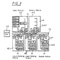
- Laboratory devices C1, C2, C3, for example, are those for handling samples in microtiter plates Pipettors, readers and incubators.
- the modules M1, M2 are the modules M1, M2 with a central Transport system TS (e.g. conveyor belt) in contact that the Transport between modules M1, M2, but also between Input storage units for the microtiter plates to be read and final storage units for read-out microtiter plates takes over.
- Transport system TS e.g. conveyor belt
- the transfer to the units E1, E2 can, for example via slide units while raising and lowering the microtiter plates or done with a gripper.
- 3 represents the overall system according to the invention, consisting of from the central transport system TS and input and Execution buffers EAP for the transfer or transfer of microtiter plates to / from the TS transport system.
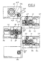
- Fig. 4 shows a detailed illustration. Here takes over a DT rotary table with its two plate positions Function of the input and output buffer EAP. Over a Stop and push device (not shown) becomes one Microplate MTP raised from the central transport system TS and transported on the turntable DT.
- microtiter plate MTP can be charged when rotating the turntable DT then towards the module output or one Staplers ZP transported to stack the MTP microtiter plates can be.
- the freedom from collision can be achieved, for example, via a Guaranteed sensor that detects whether the respective Side of the turntable DT is free, so that a microtiter plate MTP can be charged for return transport.
- turntable DT is always a microtiter plate Introduces MTP and another microtiter plate MTP performs.
- the RE module can also be part of a module M for optical readout of the MTP microtiter plates, in Fig.4 shown for example in module M3.
- the readout by means of the RE reader can be carried out one or more times take place, both in transmitted light or in incident light, where absorption, fluorescence, luminescence, scintillation or other effects that occur for the incremental samples can be determined.
- the detection of fluorescence is, for example, in the Publication 1. on the state of the art, pages 357 to 365.
- Additional buffers can be installed in modules M1 to M5 ZP may be provided for the MTP microtiter plates.
- sample preparation can also be carried out via module M2 take place and in module M3 the readout via a optical reader RE.
- a module PSP is provided as an example in module M1, via a transfer system TRS and a turntable DT is connected to the transport system TS.
- Module M5 can be equipped with additional devices and over a turntable DT connected to the transport system TS.
Landscapes
- Chemical & Material Sciences (AREA)
- Chemical Kinetics & Catalysis (AREA)
- Physics & Mathematics (AREA)
- Health & Medical Sciences (AREA)
- Life Sciences & Earth Sciences (AREA)
- Analytical Chemistry (AREA)
- Biochemistry (AREA)
- General Health & Medical Sciences (AREA)
- General Physics & Mathematics (AREA)
- Immunology (AREA)
- Pathology (AREA)
- Automatic Analysis And Handling Materials Therefor (AREA)
- Pharmaceuticals Containing Other Organic And Inorganic Compounds (AREA)
- Investigating Or Analyzing Non-Biological Materials By The Use Of Chemical Means (AREA)
- Control Of Conveyors (AREA)
- Apparatus Associated With Microorganisms And Enzymes (AREA)
Description
- HTS High Throughput Screening
- MTP Mikrotiterplatte
- SPS Speicherprogrammierbare Steuerung
- einem linearen Transportsystem mit Greifer;
- einem Dreh-Schub-Arm mit Greifer und entsprechender Anordnung der Module (vgl. Veröffentlichung 5. zum Stand der Technik);
- einem Förderband mit Stoppern und Ein/Ausschleusungen für die Platten an den Modulen.
- mittels Greifern als "pick and place"-Operationen;
- durch Stopper auf dem Band in Verbindung mit Ein- und Ausschiebern zwischen Transportsystem und den einzelnen Komponenten;
- Drehtellern mit je 2 Aufnahmen für MTP's, zwischen denen die Platten bewegt werden;
- einem Knickarmroboter (vgl. Veröffentlichung 5. zum Stand der Technik), in dessen Reichweite die einzelnen Komponenten sich befinden.
- Speicherprogrammierbarer Steuerung (SPS) wie z.B. Siemens S5
- Industrie PC mit Steckplätzen
- Mikrocontroller mit Peripheribausteinen (PLC= Programmable Logic Controller).
- Speicherprogrammierbarer Steuerung (SPS) wie z.B. Siemens S5 oder auch
- Industrie PC mit Steckplätzen.
- Fig.1
- Darstellung der Kommunikation via Ethernet mittels TCP/IP
- Fig.2
- das Prinzip des synchronen/asynchronen Plattentransportes
- Fig.3
- das erfindungsgemäße Gesamtsystem
- Fig.4
- Übernahme oder Übergabe von Mikrotiterplatten an/vom Transportsystem
Claims (3)
- Transportsystem zum Transport und Handling von Mikrotiterplatten (MPT), vorzugsweise für den Einsatz im High Throughput Screening, umfassenddadurch gekennzeichnet, daßmehrere Module mit Mitteln zur Probenvorbereitung und zum Auslesen der Proben in den Mikrotiterplatten (MPT),ein zentrales Transportsystem (TS) zum asynchronen Transfer der Mikrotiterplatten (MPT) zwischen den einzelnen Modulen (M) vorhanden ist, wobeiEin- und Ausgabepuffer (EAP) zur Übernahme der Mikrotiterplatten (MPT) von dem zentralen Transportsystem (TS) in die Module (M) bzw. zur Übergabe der Mikrotiterplatten (MPT) von den Modulen an das zentrale Transportsystem (TS) vorgesehen sind.
- Transportsystem nach Anspruch 1, bei dem die Ein- und Ausgabepuffer (EAP) aus Drehtellern (DT) gebildet sind, die mehrere Haltepositionen für die Mikrotiterplatten (MPT) aufweisen.
- Transportsystem nach einem der vorgenannten Ansprüche, bei dem mindestens eines der Module (M) mit einem Lokalrechner (PC) mit nach außen standardisierter Schnittstelle verbunden ist und mit einem Leitrechners (LR) über diese Schnittstellen der Transport und/oder die Verarbeitung und/oder die Bestückung und/oder das optische Auslesen gesteuert wird.
Applications Claiming Priority (3)
| Application Number | Priority Date | Filing Date | Title |
|---|---|---|---|
| DE19835071A DE19835071A1 (de) | 1998-08-04 | 1998-08-04 | Transportsystem zum Handling von Mikrotiterplatten |
| DE19835071 | 1998-08-04 | ||
| PCT/EP1999/005542 WO2000008473A1 (de) | 1998-08-04 | 1999-07-30 | Einrichtung zum transport und zur handhabung von mikrotiterplatten |
Publications (2)
| Publication Number | Publication Date |
|---|---|
| EP1019732A1 EP1019732A1 (de) | 2000-07-19 |
| EP1019732B1 true EP1019732B1 (de) | 2003-10-29 |
Family
ID=7876337
Family Applications (1)
| Application Number | Title | Priority Date | Filing Date |
|---|---|---|---|
| EP99940103A Expired - Lifetime EP1019732B1 (de) | 1998-08-04 | 1999-07-30 | Einrichtung zum transport und zur handhabung von mikrotiterplatten |
Country Status (7)
| Country | Link |
|---|---|
| US (1) | US7597848B1 (de) |
| EP (1) | EP1019732B1 (de) |
| JP (1) | JP4257032B2 (de) |
| AT (1) | ATE253225T1 (de) |
| AU (1) | AU5417199A (de) |
| DE (2) | DE19835071A1 (de) |
| WO (1) | WO2000008473A1 (de) |
Families Citing this family (17)
| Publication number | Priority date | Publication date | Assignee | Title |
|---|---|---|---|---|
| DE20006548U1 (de) * | 2000-04-08 | 2001-08-23 | MWG-BIOTECH AG, 85560 Ebersberg | Vorrichtung zum Durchführen von chemischen bzw. biologischen Verfahren |
| DE20006549U1 (de) * | 2000-04-08 | 2001-08-16 | MWG-BIOTECH AG, 85560 Ebersberg | Vorrichtung zum Durchführen von chemischen bzw. biologischen Verfahren |
| WO2003061830A1 (en) † | 2002-01-25 | 2003-07-31 | Thermo Crs Ltd. | Modular robotic system for sample processing |
| DE102004043399A1 (de) * | 2004-09-03 | 2006-03-09 | Bioplan Consulting Gmbh | Anlage zur Behandlung mikrobiologischer Proben |
| ATE391918T1 (de) * | 2004-11-25 | 2008-04-15 | Hoffmann La Roche | Vorrichtung zum analysieren von proben |
| DE102005013915A1 (de) * | 2005-03-24 | 2006-09-28 | Siemens Ag | Verfahrenstechnische, insbesondere mikroverfahrenstechnische Anlage |
| US20090181359A1 (en) * | 2007-10-25 | 2009-07-16 | Lou Sheng C | Method of performing ultra-sensitive immunoassays |
| US8222048B2 (en) | 2007-11-05 | 2012-07-17 | Abbott Laboratories | Automated analyzer for clinical laboratory |
| CN101960312B (zh) * | 2008-03-07 | 2014-06-11 | 希森美康株式会社 | 分析装置及测定单元 |
| WO2010092883A1 (ja) | 2009-02-12 | 2010-08-19 | アークレイ株式会社 | 分析方法、分析装置、前記分析方法の実施に用いられるプログラム、このプログラムの記憶媒体および採取装置 |
| EP2363713B1 (de) * | 2010-03-04 | 2015-06-03 | F.Hoffmann-La Roche Ag | Hardware-Architektur für Analysiergeräte |
| EP2363712B1 (de) * | 2010-03-04 | 2013-05-22 | F.Hoffmann-La Roche Ag | Arbeitsflusszeitvorgabe zwischen Modulen |
| DE102010019998A1 (de) * | 2010-05-10 | 2011-11-10 | Thermo Electron Led Gmbh | Objekthandhabungssystem zum Zuführen von Objekten zu einem Inkubator |
| EP2830772B1 (de) * | 2012-03-29 | 2022-11-09 | Siemens Healthcare Diagnostics Inc. | Mit einem automatisierungssystem kombinierbares modultransportsystem |
| US8790599B2 (en) | 2012-08-13 | 2014-07-29 | David Childs | Microtiter plate system and method |
| US10252860B2 (en) | 2015-01-09 | 2019-04-09 | HighRes Biosolutions, Inc. | Modular sample storage system |
| US11912512B2 (en) * | 2021-05-13 | 2024-02-27 | HighRes Biosolutions, Inc. | Overhead labware transport system |
Family Cites Families (16)
| Publication number | Priority date | Publication date | Assignee | Title |
|---|---|---|---|---|
| CH568793A5 (de) * | 1974-02-15 | 1975-11-14 | Mettler Instrumente Ag | |
| DE3586892T2 (de) * | 1984-09-18 | 1993-05-06 | Sumitomo Electric Industries | Vorrichtung zum trennen von zellen. |
| US5087423A (en) * | 1988-10-20 | 1992-02-11 | Olympus Optical Co., Ltd. | Automatic analyzing apparatus comprising a plurality of analyzing modules |
| DE3841961A1 (de) * | 1988-12-14 | 1990-06-21 | Dynatech Ag Branch Denkendorf | Geraet zur analyse von physiologischen oder anderen fluessigkeiten in den vertiefungen einer mikrotestplatte |
| DE4103059A1 (de) * | 1991-02-01 | 1992-08-13 | Gutehoffnungshuette Man | Metallurgisches, vollautomatisch arbeitendes labor |
| JP3164403B2 (ja) * | 1992-03-27 | 2001-05-08 | オリンパス光学工業株式会社 | 自動分析装置 |
| DE69313463T2 (de) * | 1992-12-23 | 1998-02-05 | Univ Nebraska | Verfahren zur automatischen pruefung von laborproben |
| US5492831A (en) * | 1994-11-15 | 1996-02-20 | Lachat Instruments | Shared peripheral analytical system |
| US5623415A (en) * | 1995-02-16 | 1997-04-22 | Smithkline Beecham Corporation | Automated sampling and testing of biological materials |
| GB9525794D0 (en) | 1995-12-18 | 1996-02-21 | Hale Alan | Biotechnological process |
| JP3031242B2 (ja) * | 1996-05-20 | 2000-04-10 | 株式会社日立製作所 | 多項目分析装置 |
| US5968731A (en) * | 1996-12-10 | 1999-10-19 | The Regents Of The University Of California | Apparatus for automated testing of biological specimens |
| JP3336894B2 (ja) * | 1997-01-29 | 2002-10-21 | 株式会社日立製作所 | 自動分析装置 |
| US5985214A (en) * | 1997-05-16 | 1999-11-16 | Aurora Biosciences Corporation | Systems and methods for rapidly identifying useful chemicals in liquid samples |
| US5928952A (en) * | 1997-11-05 | 1999-07-27 | Zymark Corporation | Scheduled system and method for processing chemical products |
| EP0915341B1 (de) | 1997-11-05 | 2007-06-20 | Caliper Life Sciences, Inc. | Robotersystem zur Verarbeitung von chemischen Erzeugnissen |
-
1998
- 1998-08-04 DE DE19835071A patent/DE19835071A1/de not_active Ceased
-
1999
- 1999-07-30 AT AT99940103T patent/ATE253225T1/de not_active IP Right Cessation
- 1999-07-30 WO PCT/EP1999/005542 patent/WO2000008473A1/de not_active Ceased
- 1999-07-30 DE DE59907536T patent/DE59907536D1/de not_active Expired - Lifetime
- 1999-07-30 US US09/509,921 patent/US7597848B1/en not_active Expired - Fee Related
- 1999-07-30 AU AU54171/99A patent/AU5417199A/en not_active Abandoned
- 1999-07-30 JP JP2000564056A patent/JP4257032B2/ja not_active Expired - Lifetime
- 1999-07-30 EP EP99940103A patent/EP1019732B1/de not_active Expired - Lifetime
Also Published As
| Publication number | Publication date |
|---|---|
| DE19835071A1 (de) | 2000-02-10 |
| ATE253225T1 (de) | 2003-11-15 |
| HK1031762A1 (en) | 2001-06-22 |
| EP1019732A1 (de) | 2000-07-19 |
| US7597848B1 (en) | 2009-10-06 |
| JP4257032B2 (ja) | 2009-04-22 |
| WO2000008473A1 (de) | 2000-02-17 |
| AU5417199A (en) | 2000-02-28 |
| DE59907536D1 (de) | 2003-12-04 |
| JP2002522768A (ja) | 2002-07-23 |
Similar Documents
| Publication | Publication Date | Title |
|---|---|---|
| EP1019732A1 (de) | Einrichtung zum transport und zur handhabung von mikrotiterplatten | |
| EP2730927B1 (de) | Reagenzstation für ein automatisches Analysegerät | |
| US7390458B2 (en) | High throughput processing system and method of using | |
| DE602004012915T2 (de) | Automatisches Analysengerät | |
| DE112010000822B4 (de) | Automatische Analysevorrichtung und automatisches Analyseverfahren | |
| DE60201269T2 (de) | Verfahren und system zur automatischen immunchemischen analyse | |
| DE69415739T2 (de) | Verahren und vorrichtung zur schrittweisen bewegung von gegenstaenden | |
| EP3216517B1 (de) | Verfahren zum durchmischen einer flüssigkeit in einem automatischen analysegerät | |
| WO1987005401A1 (fr) | Analyseur photometrique | |
| Armstrong | A review of high-throughput screening approaches for drug discovery | |
| EP2857842B1 (de) | Zugriffssteuerung für ein Laborgerät, Laborgerät mit Zugriffssteuerung und Verfahren zur gerätegesteuerten Behandlung von Laborproben | |
| EP2857843A1 (de) | System aufweisend mindestens zwei Laborgeräte zur gerätegesteuerten Bearbeitung einer Teilaufgabe bei einem Behandlungsprozess beinhaltend Behandlungen mindestens einer Laborprobe, Laborgerät und Verfahren | |
| US20050271551A1 (en) | Liquid chemical distribution method and apparatus | |
| WO2008068181A1 (de) | Anordnung zur aufbereitung einer mehrzahl von proben für eine analyse | |
| DE10020704A1 (de) | Biochip zur Archivierung und labormedizinischen Analyse von biologischem Probenmaterial, Verfahren zu dessen Herstellung sowie dessen Verwendung in diagnostischen Verfahren | |
| DE102023002147A1 (de) | Modulare automatisierte vorrichtung zur durchführung chemischer und/oder biologischer experimente | |
| US20030225477A1 (en) | Modular equipment apparatus and method for handling labware | |
| EP2322939A1 (de) | Analysesystem und Analyseverfahren | |
| Meldrum | Engineering in genomics: the interdisciplinary nature of genomics | |
| HK1031762B (en) | Device for transporting and handling microtiter plates | |
| EP3211423A1 (de) | Automatisches analysegerät mit aufnahmepositionen für flüssigkeitsbehälter | |
| Golas et al. | A purpose-built open source liquid handler for industry-class automated experiments | |
| Menke | Unit automation in high throughput screening | |
| Little et al. | Recent advances in robotic automation of microplate assays | |
| DE10117274B4 (de) | Verfahren zur Analyse und Archivierung von wenigstens einer Materialbibliothek |
Legal Events
| Date | Code | Title | Description |
|---|---|---|---|
| PUAI | Public reference made under article 153(3) epc to a published international application that has entered the european phase |
Free format text: ORIGINAL CODE: 0009012 |
|
| 17P | Request for examination filed |
Effective date: 20000414 |
|
| AK | Designated contracting states |
Kind code of ref document: A1 Designated state(s): AT BE CH CY DE DK ES FI FR GB GR IE IT LI LU MC NL PT SE |
|
| 17Q | First examination report despatched |
Effective date: 20010918 |
|
| GRAH | Despatch of communication of intention to grant a patent |
Free format text: ORIGINAL CODE: EPIDOS IGRA |
|
| GRAS | Grant fee paid |
Free format text: ORIGINAL CODE: EPIDOSNIGR3 |
|
| GRAA | (expected) grant |
Free format text: ORIGINAL CODE: 0009210 |
|
| AK | Designated contracting states |
Kind code of ref document: B1 Designated state(s): AT BE CH CY DE DK ES FI FR GB GR IE IT LI LU MC NL PT SE |
|
| PG25 | Lapsed in a contracting state [announced via postgrant information from national office to epo] |
Ref country code: NL Free format text: LAPSE BECAUSE OF FAILURE TO SUBMIT A TRANSLATION OF THE DESCRIPTION OR TO PAY THE FEE WITHIN THE PRESCRIBED TIME-LIMIT Effective date: 20031029 Ref country code: IT Free format text: LAPSE BECAUSE OF FAILURE TO SUBMIT A TRANSLATION OF THE DESCRIPTION OR TO PAY THE FEE WITHIN THE PRESCRIBED TIME-LIMIT;WARNING: LAPSES OF ITALIAN PATENTS WITH EFFECTIVE DATE BEFORE 2007 MAY HAVE OCCURRED AT ANY TIME BEFORE 2007. THE CORRECT EFFECTIVE DATE MAY BE DIFFERENT FROM THE ONE RECORDED. Effective date: 20031029 Ref country code: IE Free format text: LAPSE BECAUSE OF FAILURE TO SUBMIT A TRANSLATION OF THE DESCRIPTION OR TO PAY THE FEE WITHIN THE PRESCRIBED TIME-LIMIT Effective date: 20031029 Ref country code: FI Free format text: LAPSE BECAUSE OF FAILURE TO SUBMIT A TRANSLATION OF THE DESCRIPTION OR TO PAY THE FEE WITHIN THE PRESCRIBED TIME-LIMIT Effective date: 20031029 Ref country code: CY Free format text: LAPSE BECAUSE OF FAILURE TO SUBMIT A TRANSLATION OF THE DESCRIPTION OR TO PAY THE FEE WITHIN THE PRESCRIBED TIME-LIMIT Effective date: 20031029 |
|
| REG | Reference to a national code |
Ref country code: GB Ref legal event code: FG4D Free format text: NOT ENGLISH |
|
| REG | Reference to a national code |
Ref country code: CH Ref legal event code: EP |
|
| REG | Reference to a national code |
Ref country code: CH Ref legal event code: NV Representative=s name: KATZAROV S.A. |
|
| REG | Reference to a national code |
Ref country code: IE Ref legal event code: FG4D Free format text: GERMAN |
|
| REF | Corresponds to: |
Ref document number: 59907536 Country of ref document: DE Date of ref document: 20031204 Kind code of ref document: P |
|
| PG25 | Lapsed in a contracting state [announced via postgrant information from national office to epo] |
Ref country code: SE Free format text: LAPSE BECAUSE OF FAILURE TO SUBMIT A TRANSLATION OF THE DESCRIPTION OR TO PAY THE FEE WITHIN THE PRESCRIBED TIME-LIMIT Effective date: 20040129 Ref country code: GR Free format text: LAPSE BECAUSE OF FAILURE TO SUBMIT A TRANSLATION OF THE DESCRIPTION OR TO PAY THE FEE WITHIN THE PRESCRIBED TIME-LIMIT Effective date: 20040129 Ref country code: DK Free format text: LAPSE BECAUSE OF FAILURE TO SUBMIT A TRANSLATION OF THE DESCRIPTION OR TO PAY THE FEE WITHIN THE PRESCRIBED TIME-LIMIT Effective date: 20040129 |
|
| PG25 | Lapsed in a contracting state [announced via postgrant information from national office to epo] |
Ref country code: ES Free format text: LAPSE BECAUSE OF FAILURE TO SUBMIT A TRANSLATION OF THE DESCRIPTION OR TO PAY THE FEE WITHIN THE PRESCRIBED TIME-LIMIT Effective date: 20040209 |
|
| GBT | Gb: translation of ep patent filed (gb section 77(6)(a)/1977) |
Effective date: 20040204 |
|
| NLV1 | Nl: lapsed or annulled due to failure to fulfill the requirements of art. 29p and 29m of the patents act | ||
| REG | Reference to a national code |
Ref country code: IE Ref legal event code: FD4D |
|
| PG25 | Lapsed in a contracting state [announced via postgrant information from national office to epo] |
Ref country code: LU Free format text: LAPSE BECAUSE OF NON-PAYMENT OF DUE FEES Effective date: 20040730 Ref country code: AT Free format text: LAPSE BECAUSE OF NON-PAYMENT OF DUE FEES Effective date: 20040730 |
|
| PG25 | Lapsed in a contracting state [announced via postgrant information from national office to epo] |
Ref country code: MC Free format text: LAPSE BECAUSE OF NON-PAYMENT OF DUE FEES Effective date: 20040731 Ref country code: BE Free format text: LAPSE BECAUSE OF NON-PAYMENT OF DUE FEES Effective date: 20040731 |
|
| ET | Fr: translation filed | ||
| PLBE | No opposition filed within time limit |
Free format text: ORIGINAL CODE: 0009261 |
|
| STAA | Information on the status of an ep patent application or granted ep patent |
Free format text: STATUS: NO OPPOSITION FILED WITHIN TIME LIMIT |
|
| 26N | No opposition filed |
Effective date: 20040730 |
|
| BERE | Be: lapsed |
Owner name: F. *HOFFMANN-LA ROCHE A.G. Effective date: 20040731 Owner name: CARL *ZEISS JENA G.M.B.H. Effective date: 20040731 |
|
| BERE | Be: lapsed |
Owner name: F. *HOFFMANN-LA ROCHE A.G. Effective date: 20040731 Owner name: CARL *ZEISS JENA G.M.B.H. Effective date: 20040731 |
|
| PG25 | Lapsed in a contracting state [announced via postgrant information from national office to epo] |
Ref country code: PT Free format text: LAPSE BECAUSE OF NON-PAYMENT OF DUE FEES Effective date: 20040329 |
|
| REG | Reference to a national code |
Ref country code: CH Ref legal event code: PUE Owner name: PERKINELMER CELLULAR TECHNOLOGIES GERMANY GMBH, DE Free format text: FORMER OWNER: F. HOFFMANN-LA ROCHE AG, DE |
|
| REG | Reference to a national code |
Ref country code: DE Ref legal event code: R082 Ref document number: 59907536 Country of ref document: DE Representative=s name: GEYER, FEHNERS & PARTNER (G.B.R.), DE |
|
| REG | Reference to a national code |
Ref country code: CH Ref legal event code: PK Free format text: BERICHTIGUNG INHABER |
|
| REG | Reference to a national code |
Ref country code: DE Ref legal event code: R082 Ref document number: 59907536 Country of ref document: DE Representative=s name: PATENTANWAELTE GEYER, FEHNERS & PARTNER MBB, DE Effective date: 20130415 Ref country code: DE Ref legal event code: R082 Ref document number: 59907536 Country of ref document: DE Representative=s name: GEYER, FEHNERS & PARTNER (G.B.R.), DE Effective date: 20130415 Ref country code: DE Ref legal event code: R081 Ref document number: 59907536 Country of ref document: DE Owner name: PERKINELMER CELLULAR TECHNOLOGIES GERMANY GMBH, DE Free format text: FORMER OWNERS: CARL ZEISS JENA GMBH, 07745 JENA, DE; F. HOFFMANN-LA ROCHE AG, 4070 BASEL, CH Effective date: 20130415 Ref country code: DE Ref legal event code: R081 Ref document number: 59907536 Country of ref document: DE Owner name: F. HOFFMANN-LA ROCHE AG, CH Free format text: FORMER OWNERS: CARL ZEISS JENA GMBH, 07745 JENA, DE; F. HOFFMANN-LA ROCHE AG, 4070 BASEL, CH Effective date: 20130415 Ref country code: DE Ref legal event code: R081 Ref document number: 59907536 Country of ref document: DE Owner name: F. HOFFMANN-LA ROCHE AG, CH Free format text: FORMER OWNER: CARL ZEISS JENA GMBH, F. HOFFMANN-LA ROCHE AG, , CH Effective date: 20130415 Ref country code: DE Ref legal event code: R081 Ref document number: 59907536 Country of ref document: DE Owner name: PERKINELMER CELLULAR TECHNOLOGIES GERMANY GMBH, DE Free format text: FORMER OWNER: CARL ZEISS JENA GMBH, F. HOFFMANN-LA ROCHE AG, , CH Effective date: 20130415 |
|
| REG | Reference to a national code |
Ref country code: FR Ref legal event code: TP Owner name: PERKINELMER CELLULAR TECHNOLOGIES GERMANY GMBH, DE Effective date: 20130523 |
|
| REG | Reference to a national code |
Ref country code: GB Ref legal event code: 732E Free format text: REGISTERED BETWEEN 20130613 AND 20130619 |
|
| REG | Reference to a national code |
Ref country code: CH Ref legal event code: PCAR Free format text: NEW ADDRESS: EIGERSTRASSE 2 POSTFACH, 3000 BERN 14 (CH) |
|
| REG | Reference to a national code |
Ref country code: FR Ref legal event code: PLFP Year of fee payment: 18 |
|
| REG | Reference to a national code |
Ref country code: FR Ref legal event code: PLFP Year of fee payment: 19 |
|
| REG | Reference to a national code |
Ref country code: FR Ref legal event code: PLFP Year of fee payment: 20 |
|
| PGFP | Annual fee paid to national office [announced via postgrant information from national office to epo] |
Ref country code: FR Payment date: 20180726 Year of fee payment: 20 Ref country code: DE Payment date: 20180727 Year of fee payment: 20 |
|
| PGFP | Annual fee paid to national office [announced via postgrant information from national office to epo] |
Ref country code: CH Payment date: 20180801 Year of fee payment: 20 Ref country code: GB Payment date: 20180727 Year of fee payment: 20 |
|
| REG | Reference to a national code |
Ref country code: DE Ref legal event code: R071 Ref document number: 59907536 Country of ref document: DE |
|
| REG | Reference to a national code |
Ref country code: CH Ref legal event code: PL |
|
| REG | Reference to a national code |
Ref country code: GB Ref legal event code: PE20 Expiry date: 20190729 |
|
| PG25 | Lapsed in a contracting state [announced via postgrant information from national office to epo] |
Ref country code: GB Free format text: LAPSE BECAUSE OF EXPIRATION OF PROTECTION Effective date: 20190729 |