EP1019894B1 - Virtuelle retinale anzeige mit erweitertem pupillenausgang - Google Patents
Virtuelle retinale anzeige mit erweitertem pupillenausgang Download PDFInfo
- Publication number
- EP1019894B1 EP1019894B1 EP97908830A EP97908830A EP1019894B1 EP 1019894 B1 EP1019894 B1 EP 1019894B1 EP 97908830 A EP97908830 A EP 97908830A EP 97908830 A EP97908830 A EP 97908830A EP 1019894 B1 EP1019894 B1 EP 1019894B1
- Authority
- EP
- European Patent Office
- Prior art keywords
- light
- exit
- eyepiece
- angle
- exit pupil
- Prior art date
- Legal status (The legal status is an assumption and is not a legal conclusion. Google has not performed a legal analysis and makes no representation as to the accuracy of the status listed.)
- Expired - Lifetime
Links
- 210000001747 pupil Anatomy 0.000 title claims abstract description 173
- 230000002207 retinal effect Effects 0.000 title claims description 31
- 230000003287 optical effect Effects 0.000 claims abstract description 51
- 238000000034 method Methods 0.000 claims description 10
- 239000013307 optical fiber Substances 0.000 claims description 10
- 230000004424 eye movement Effects 0.000 claims 2
- 238000005452 bending Methods 0.000 claims 1
- 239000000835 fiber Substances 0.000 abstract description 18
- 210000001525 retina Anatomy 0.000 description 25
- 230000008901 benefit Effects 0.000 description 8
- 238000010586 diagram Methods 0.000 description 7
- 230000000694 effects Effects 0.000 description 7
- 230000001427 coherent effect Effects 0.000 description 5
- 230000001186 cumulative effect Effects 0.000 description 3
- 210000003128 head Anatomy 0.000 description 3
- 238000003384 imaging method Methods 0.000 description 3
- XEEYBQQBJWHFJM-UHFFFAOYSA-N Iron Chemical compound [Fe] XEEYBQQBJWHFJM-UHFFFAOYSA-N 0.000 description 2
- 230000015572 biosynthetic process Effects 0.000 description 2
- 238000009125 cardiac resynchronization therapy Methods 0.000 description 2
- 230000008859 change Effects 0.000 description 2
- 239000000284 extract Substances 0.000 description 2
- 229910000639 Spring steel Inorganic materials 0.000 description 1
- 238000003491 array Methods 0.000 description 1
- 230000004397 blinking Effects 0.000 description 1
- 239000003086 colorant Substances 0.000 description 1
- 229910003460 diamond Inorganic materials 0.000 description 1
- 239000010432 diamond Substances 0.000 description 1
- 230000008030 elimination Effects 0.000 description 1
- 238000003379 elimination reaction Methods 0.000 description 1
- 230000006870 function Effects 0.000 description 1
- 238000001093 holography Methods 0.000 description 1
- 238000001746 injection moulding Methods 0.000 description 1
- 229910052742 iron Inorganic materials 0.000 description 1
- 239000004973 liquid crystal related substance Substances 0.000 description 1
- 230000007774 longterm Effects 0.000 description 1
- 238000003754 machining Methods 0.000 description 1
- 238000004519 manufacturing process Methods 0.000 description 1
- 239000000463 material Substances 0.000 description 1
- 230000004048 modification Effects 0.000 description 1
- 238000012986 modification Methods 0.000 description 1
- 230000008447 perception Effects 0.000 description 1
- 230000000737 periodic effect Effects 0.000 description 1
- 230000002093 peripheral effect Effects 0.000 description 1
- 230000004044 response Effects 0.000 description 1
- 230000000284 resting effect Effects 0.000 description 1
- 238000004804 winding Methods 0.000 description 1
Images


Classifications
-
- G—PHYSICS
- G02—OPTICS
- G02B—OPTICAL ELEMENTS, SYSTEMS OR APPARATUS
- G02B26/00—Optical devices or arrangements for the control of light using movable or deformable optical elements
- G02B26/08—Optical devices or arrangements for the control of light using movable or deformable optical elements for controlling the direction of light
- G02B26/10—Scanning systems
- G02B26/101—Scanning systems with both horizontal and vertical deflecting means, e.g. raster or XY scanners
-
- G—PHYSICS
- G02—OPTICS
- G02B—OPTICAL ELEMENTS, SYSTEMS OR APPARATUS
- G02B27/00—Optical systems or apparatus not provided for by any of the groups G02B1/00 - G02B26/00, G02B30/00
- G02B27/0081—Optical systems or apparatus not provided for by any of the groups G02B1/00 - G02B26/00, G02B30/00 with means for altering, e.g. enlarging, the entrance or exit pupil
-
- G—PHYSICS
- G02—OPTICS
- G02B—OPTICAL ELEMENTS, SYSTEMS OR APPARATUS
- G02B27/00—Optical systems or apparatus not provided for by any of the groups G02B1/00 - G02B26/00, G02B30/00
- G02B27/01—Head-up displays
- G02B27/017—Head mounted
-
- G—PHYSICS
- G02—OPTICS
- G02B—OPTICAL ELEMENTS, SYSTEMS OR APPARATUS
- G02B27/00—Optical systems or apparatus not provided for by any of the groups G02B1/00 - G02B26/00, G02B30/00
- G02B27/01—Head-up displays
- G02B27/017—Head mounted
- G02B27/0172—Head mounted characterised by optical features
Definitions
- This invention relates to retinal display devices, and more particularly to optical configurations for retinal display devices and a method and apparatus for defining an exit pupil through which a user views an image.
- a retinal display device is an optical device for generating an image upon the retina of an eye.
- Conventional retinal scanning displays use a coherent light source which is scanned in raster fashion onto the retina. Light is emitted from a light source, collimated through a lens, then passed through a scanning device. The scanning device defines a scanning pattern for the light. Following the scanning device, the scanned light passes through an objective lens which converges the light to focus an image. Conventionally such light is converged to a flat image plane. The light then diverges beyond the plane. An eyepiece is positioned along the light path beyond the objective lens at some desired focal length. An "exit pupil" (i.e., area of generated light pattern) occurs shortly beyond the eyepiece in an area where a viewer's eye pupil is to be positioned.
- a viewer looks into the eye piece to view an image.
- the eye piece receives light that is being deflected along a raster pattern. Light thus impinges on the viewer's eye pupil at differing angles at different times during the scanning cycle. This range of angles determines the size of the image perceived by the viewer. Modulation of the light during the scanning cycle determines the content of the image.
- the exit pupil defined by the display device is less than 2 mm in diameter and often less than 1 mm in diameter.
- the viewer's eye pupil varies from approximately 2 mm in diameter under bright light to approximately 7 mm in a dark room. Because of the small exit pupil, a first step for a viewer is to adjust eye position to find the exit pupil. The viewer's pupil needs to achieve and maintain alignment with the display device's exit pupil. While in alignment, the light scans directly onto the viewer's retina without any intermediary screens, cathode ray tubes (CRT's) or liquid crystal display devices (LCD's). The result is an image perceived by the viewer.
- CTR's cathode ray tubes
- LCD's liquid crystal display devices
- a shortcoming of the conventional retinal display is the difficulty of maintaining alignment between the exit pupil and the viewer's pupil. If the viewer moves, alignment may be lost. Movement is problematic because a viewer has a tendency to move their eye when intending to view a peripheral portion of the image. Even blinking may cause movement of the eye. As a result, conventional exit pupils are inconvenient for the viewer. In particular a lay consumer using a virtual retinal display would find the alignment requirement difficult to maintain for entertainment or other long term viewing applications. Accordingly there is a need for a retinal display device having an exit pupil defined so as to enable easier viewing of the image.
- a lightweight, compact retinal display device is achieved using a simplified optical system which generates an expanded exit pupil without compromising magnification or resolution.
- a scanning device for deflecting light is located along the light path following an objective lens system.
- the retinal display device of this invention avoids use of an objective lens system following the scanning device. The elimination of an objective lens system beyond the scanner shortens the light path through the retinal display device.
- One advantage of such a configuration is a lighter, more compact display device.
- the scanning device receives converging light. Beyond the scanning device, the light continues to converge to an intermediate image plane.
- the image plane is an intermediate curved image plane. The light then diverges beyond this plane in the direction of an eyepiece.
- an apparatus for expanding the exit pupil is positioned between the scanning device and the eyepiece at the curved image plane.
- the exit pupil expanding apparatus defines a curved surface which coincides with the intermediate curved image plane.
- the apparatus is positioned at the intermediate curved image plane so as to maintain maximum resolution and focus.
- one embodiment of the exit pupil expanding apparatus is formed by a diffractive optical element.
- the diffractive optical element has a curved surface receiving light from the scanning device. Such curved surface coincides with the intermediate curved image plane scanned by the scanning device.
- the diffractive optical element replicates the incident light beams to produce multiple exit light beams. More specifically, the diffractive optical element passes one fraction of received light in the same direction as the incident light. Additional beams are passed at specific angles relative to the incident light. The percentage of light in each beam leaving the diffractive optical element is determined by the diffraction pattern.
- the angle spanned by each exiting light beam is defined by spacing among diffraction patterns and the light wavelengths.
- the cumulative angle of light beams exiting the diffractive optical element spans an angle greater than the cumulative angle of light beams incident to the diffractive optical element.
- Each exiting light beam output from the diffractive optical element passes through the eyepiece to define a separate exit pupil.
- multiple closely spaced exit pupils are defined beyond the eyepiece in an area to coincide with a viewer's eye.
- One or more of such exit pupils of substantially the same size occur at the viewer's eye pupil. If a viewer moves their eye, the viewer's eye moves into alignment with other exit pupils.
- the average brightness of the group of exit pupils formed within the viewer's eye at any given time stays approximately the same. When the viewer moves their eye to align with a newly defined group of exit pupils, the average brightness remains approximately the same as with the previous group of exit pupils.
- another embodiment of the exit pupil expanding apparatus is formed by a bundle of aligned optical fibers, (e.g., a fiber optic face plate).
- One end of each fiber defines a portion of the curved plane which receives the light from the scanning device.
- Light enters a fiber over a given narrow angle, then exits over an enlarged angle.
- By creating an exit angle greater than the incident angle the exiting light impinges upon a larger surface of the ensuing eyepiece.
- the eye piece in turn passes light over an expanded exit pupil.
- the fiber bundle defines at its exit surface either one of a flat planar surface or curved planar surface.
- another embodiment of the exit pupil expanding apparatus is formed by a lens array.
- the lens array includes several small lenses in which each lens has a diameter on the order of 5-100 microns. Each lens is spaced as closely as possible to each adjacent lens in the array.
- the array defines a curved plane from sides of each lens facing the scanning device. Such curved plane receives the light from the scanning device. Light enters each lens over a given narrow angle, then exits over an enlarged angle. By creating an exit angle greater than the incident angle the exiting light impinges upon a larger surface of the ensuing eyepiece. As in the fiber bundle embodiment, the eyepiece in turn passes light over an expanded exit pupil.
- another embodiment of the exit pupil expanding apparatus is formed by a diffuser.
- the diffuser defines a curved surface corresponding to the intermediate curved image plane.
- the diffuser evenly spreads the passing light.
- the light output from the diffuser spans a greater angle than the light incident to the diffuser.
- the light output from the diffuser is an expanded beam which passes through the eyepiece to define an expanded exit pupil.
- some embodiments of the exit pupil expanding apparatus reflect light.
- the reflected light is used to form the expanded exit pupil(s).
- One advantage of this invention is that the shorter light path enabled by avoiding an objective after the scanning device allows for a more compact, lighter weight retinal display device. Another advantage is that a viewer has less difficulty aligning and maintaining alignment with an exit pupil formed at the eyepiece. In particular, the expanded exit pupil, the multiple exit pupils or the multiple expanded exit pupils make it easier for a viewer to align with an exit pupil. Another advantage with regard to the diffractive optical element embodiment is that image brightness is generally uniform among various groups of exit pupils which may form at the viewer's eye.
- Fig. 1 shows a block diagram of a virtual retinal display 10 according to one embodiment of this invention.
- the display 10 receives image data from a computer device, video device or other digital or analog image data source. Light generated by the display 10 is altered according to the image data to scan an image into the retina of a viewer's eye E.
- the retinal display 10 generates and manipulates light to create color or monochrome images having narrow to panoramic fields of view and low to high resolutions.
- the display 10 does not generate a "real image" as done by CRTs, LCDs or an LED array. Instead, light modulated with video information is scanned directly onto the retina of a viewer's eye E to produce the perception of an erect virtual image. Because a real image is neither generated nor portrayed on a screen, the retinal display is small in size. In particular, the retinal display is suitable for hand-held operation or for mounting on the viewer's head.
- the retinal display 10 includes an image data interface 11, a light source 12, an optics subsystem 14, a scanning subsystem 16, an exit pupil expanding apparatus 18, and an eyepiece 20.
- the image data interface 11 receives a video or other image signal, such as an RGB signal, NTSC signal, VGA signal or other formatted color or monochrome video or image data signal.
- the light source 12 includes one or more sources of light. In one embodiment red, green and blue light sources are included. The light sources or their output beams are modulated according to the input image data signal content to produce light which is input to an optics subsystem 14. In one embodiment the emitted light is coherent. In another embodiment the emitted light is noncoherent.
- the optics subsystem 14 serves as an objective to focus the light. For some embodiments in which noncoherent light is received, the optics subsystem 14 also collects the light. The light exiting the optics subsystem 14 converges toward a focal point at image plane 15. Prior to the image plane 15 is the scanning subsystem 16. The scanning subsystem 16 deflects the light and the ensuing focal point to define an image plane of focal points. Typically the light is deflected along a raster pattern, although other display formats such as vector imaging also can be used. In one embodiment the scanning subsystem 16 receives a horizontal deflection signal and a vertical deflection signal derived from the image data interface 11.
- the scanning subsystem includes a mechanical resonator for deflecting passing light.
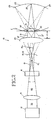
- Fig. 2 shows deflection of light 19 along one axis. As the light 19 is deflected, the focal point moves. Over the course of scanning a raster pattern the focal points define the intermediate curved image plane 15.
- the exit pupil expanding apparatus 18 is positioned at the location where the intermediate curved image plane 15 is to occur. Specifically the exit pupil expanding apparatus 18 has a curved surface upon which light 19 impinges. Such curved surface coincides with the image plane 15. The light exiting the apparatus 18 exits over an angle ⁇ o which is larger than an angle ⁇ i of incident light. As a result the light exiting the apparatus 18 spreads over a larger surface area of the eyepiece 20. This, in turn, causes a larger exit pupil 21 to occur.
- the exit pupil expanding apparatus 18 in various embodiments expands the exit pupil to define an enlarged exit pupil 21 by generating multiple closely spaced (or overlapping) exit pupils and/or by enlarging the exit pupil(s).
- a diffractive optical element embodiment generates multiple exit pupils.
- a fiber-optic face plate embodiment, lens array embodiment or diffuser embodiment enlarges a single exit pupil.
- the light output from the exit pupil expanding apparatus 18 travels to the eyepiece 20.
- the expanded exit pupil(s) occur slightly beyond the eyepiece 20 at a location where a viewer positions the pupil of their eye E.
- Fig. 2 shows light paths for three pixels of an image to be formed on the eye E retina 23.
- Light impinging on the apparatus 18 results in formation of an exit pupil 21, 21', 21" at a distance d from the eyepiece 20.
- the part numbers 21, 21', 21" depict the exit pupil at respective points in time receiving light at differing respective angles.
- the light rays forming the exit pupil 21 for a given pixel impinge upon the eye's pupil 31 at a common angle.
- the light is focused to a point 25 on the retina 23.
- Such point 25 corresponds in effect to a pixel of an image.
- Exit pupil 21' corresponds to exit pupil 21 and occurs at approximately the same 3-dimensional position relative to the eyepiece 20. This is evident from the common boundary points 33, 35 where the exit pupil 21, 21' forms at the eye pupil 31.
- Exit pupil 21' is formed by light rays impinging the eye pupil at a common angle. Such angle, however, differs from the angle of the light rays forming exit pupil 21. Due to the differing angle, the light rays forming exit pupil 21' focus at a different point 27 on the eye retina 23. Thus, by deflecting the light 19, the image point formed in the retina moves from point 25 to point 27.
- Fig. 2 further depicts formation of another image point 29 at the retina 23.
- Such point 29 is formed as the scanning subsystem 16 deflects light 19 so as to change the current focal point location within the image plane 15.
- the altered focal point causes light rays of a different angle to define an exit pupil 21".
- the light rays defining the exit pupil 21" impinge the eye pupil 31 at a common angle.
- Such common angle differs than that for exit pupils 21, 21'.
- the result is a different image point 29 formed on the eye retina 23.
- the scanning subsystem deflects the light 19, the light rays forming the exit pupil 21 (21', 21")at different moments in time impinge upon the eye pupil 31 at differing angles.
- the focal point on the retina varies.
- a raster of focal points occurs on the retina.
- the raster of focal points defines an image scanned directly on the retina.
- the eyepiece 20 preferably is positioned at one focal distance from the intermediate curved image plane 15.
- the relative distance between the image plane 15 and eyepiece is variable. In the case where the relative distance is slightly less than one focal length, the size and apparent depth of the image formed in the viewer's eye changes.
- the light source 12 includes a single or multiple light sources. For generating a monochrome image a single monochrome source typically is used. For color imaging, multiple light sources are used. Exemplary light sources are colored lasers, laser diodes or light emitting diodes (LEDs). Referring to Fig. 3 , an embodiment having a respective red photon source 22, green photon source 24 and blue photon source 26 are shown, although other colors may be used.
- LEDs do not output coherent light
- lenses are used in one embodiment to shrink the apparent size of the LED light source and achieve flatter wave fronts.
- a single mode monofilament optical fiber receives the LED output to define a point source which outputs light approximating coherent light.
- the light sources or the light generated by the light sources are modulated to include red, green and or blue components at a given point (e.g., pixel) of a resulting image.
- a given point e.g., pixel
- respective beams of light sources 22, 24, 26 are modulated to introduce color components at a given pixel.
- Red light from source 22 is output to a modulator 28 then to a beam combining apparatus 34.
- Green light from source 24 is output to a modulator 29 then to the beam combining apparatus 34.
- blue light from source 26 is output to a modulator 30 then to the beam combining apparatus 34.
- the modulators 28, 29, 30 modulate the respective beams of light according to R, G and B component signals derived from the image data signal received into the display 10.
- the beam combining apparatus 34 is formed by an arrangement of dichroic mirrors or dichroic beam splitters which direct a substantial portion of each beam into a common beam.
- the light output along such common path is light 36 which subsequently enters the optical subsystem 14.
- the retinal display device 10 is an output device which receives image data to be displayed. Such image data is received as an image data signal at the image data interface 11.
- the image data signal is a video or other image signal, such as an RGB signal, NTSC signal, VGA signal or other formatted color or monochrome video or graphics signal.
- an exemplary embodiment of the image data interface 11 extracts color component signals and synchronization signals from the received image data signal.
- the red signal is extracted and routed to the modulator 28 for modulating the red light source 22 output.
- the green signal is extracted and routed to the modulator 29 for modulating the green light source 24 output.
- the blue signal is extracted and routed to the modulator 30 for modulating the blue light source 26 output.
- the image data signal interface 11 also extracts a horizontal synchronization component and vertical synchronization component from the image data signal.
- such signals define respective frequencies for horizontal scanner and vertical scanner drive signals routed to the scanning subsystem 16.
- the optics subsystem 14 receives the output beam 36 from the beam combining apparatus 34 and converges the beam. Left undisturbed the beam converges to a focal point then diverges beyond such point. As the converging light is deflected, however, the focal point is deflected. the pattern of deflection defines a pattern of focal points. Such pattern is referred to as an intermediate image plane. Referring to Fig. 2 , such intermediate image plane 15 occurs as a curved image plane.
- the optics subsystem 14 includes an objective lens 44 which converges the light 36 received from the light source 12.
- the optic subsystem 14 includes a cylindrical lens 40 and an objective lens 44 (see Fig. 3 ).
- the cylindrical lens 40 equalizes the divergence angle of the light output from the laser diode sources.
- the objective lens 44 then converges the light toward the intermediate curved image plane 15 - (see Fig. 2 ).
- the scanning subsystem 16 receives the converging light output from the optics subsystem at a position prior to the curved image plane 15.
- the scanning subsystem 16 includes two resonant scanners 200.
- One scanner is for deflecting light along a horizontal axis.
- the other scanner is for deflecting light along a vertical axis.
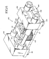
- Figs 4 and 5 show a miniature optical resonant scanner 200.
- the function of the scanner 200 is to deflect light along a horizontal axis or a vertical axis.
- a pair of scanners 200 deflect light along a raster pattern so as to define the intermediate image plane 15.
- a scanner 200 serving as the horizontal scanner receives a drive signal having a frequency defined by the horizontal synchronization signal HSYNC extracted at the image data interface 11.
- a scanner 200 serving as the vertical scanner receives a drive signal having a frequency defined by the vertical synchronization signal VSYNC extracted at the image data interface.
- Such drive signals tune a resonance circuit of the scanner 200
- the scanner 200 includes a mirror 212 driven by a magnetic circuit so as to oscillate at a high frequency about an axis of rotation 214.
- the only moving parts are the mirror 212 and a spring plate 216.
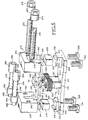
- the optical scanner 200 also includes a base plate 217 with a pair of stator posts 218, 220 centrally located thereon.
- the base plate 217 and stator posts 218, 220 are integrally formed in one piece of a soft iron.
- Stator coils 222 and 224 are wound in opposite directions about the respective stator posts 218 and 220.
- the electrical coil windings 222 and 224 may be connected in series or in parallel to a drive circuit as discussed below.
- the base 217 is formed with a seat 230 having a back stop 232 extending up from one end of the seat 230 and having a front stop 234 extending up from the seat at the opposite end thereof.
- the base 217 is formed with a seat 236 at the end of the base opposite the seat 230.
- the seat 236 includes a back stop 238 and a front stop 240 that extend upwardly from the seat 236 at the back and front thereof.
- the spring plate 216 is formed of spring steel and is a torsional type of spring having a spring constant determined by its length and width.
- the spring plate 216 has enlarged opposite ends 242 and 244 that rest directly on a pole of the respective magnets 226 and 228.
- the magnets 226 and 228 are oriented such that they have like poles adjacent the spring plate.
- the North poles of the magnet 226 and 228 could be adjacent the spring plate 216 with the South poles of the magnets 226 and 228 adjacent the base 217.
- the South poles of both magnets 226, 228 could be adjacent the spring plate with the North pole of the magnets 226, 228 adjacent the base 217.
- a narrower arm portion 246, 248 of the spring plate 216 extends from each of the enlarged ends 242, 244 to an enlarged central mirror mounting portion 250 of the spring plate 216.
- the mirror mounting portion 250 forms the armature of the optical resonant scanner 200 and is mounted directly over the stator posts 218 and 220 such that the axis of rotation 214 of the mirror mounting portion 250 is equidistant from the stator posts 218 and 220.
- the mirror 212 is mounted on or coated on the mirror mounting portion 250 of the spring plate.
- each cap 252, 258 is formed as a block with openings 260 and 262.
- the openings 260, 262 are formed so that the caps 252, 258 can accommodate the ends 242, 244 of the spring plate, the magnets 226, 228 and the seats 230, 236 as well as the arms 246 and 248 of the spring plate 216 when the caps 252, 258 are resting on the base 217.
- the cap 252 is held securely to the base 217 by a pair of screws 254 and 256 so as to clamp the spring plate 216 and magnet 226 to the base.
- the screws 254 and 256 extend up through apertures 258 in the base 217 on opposite sides of the seat 230 and into threaded apertures formed in the cap 252 on opposite sides of the opening 260.
- the cap 258 is similarly clamped to the base 217 by respective screws 261 and 263 that extend up through respective apertures 264 formed on opposite sides of the cap opening 262.
- Magnetic circuits are formed in the optical scanner 200 so as to oscillate the mirror 212 about the axis of rotation 214 in response to an alternating drive signal.
- One magnetic circuit extends from the top pole of the magnets 226 to the spring plate end 242, through the arms 246 and mirror mounting portion 250 of the spring plate 216, across a gap to the stator 218 and through the base 217 back to the magnet 226 through its bottom pole.
- Another magnetic circuit extends from the top pole of the magnet 228 to the spring plate end 244 through the arm 248 and mirror mounting portion 250 of the spring plate 216, across a gap to the stator 218 and through the base 217 back to the magnet 228 through its bottom pole.
- magnet circuits are set up through the stator 220 as follows.
- One magnetic circuit extends from the top pole of the magnet 226 to the spring plate end 242, through the arm 246 and mirror mounting portion of the spring plate 216, across the gap to the stator 220 and through the base 217 back to the magnet 226 through its bottom pole.
- Another magnetic circuit extends from the top pole of the magnet 228 to the spring plate end 244, through the arm 248 and mirror mounting portion 250 of the spring plate 216, across the gap to the stator 220 and then through the base 217 back to the magnet 228 through its bottom pole.
- a periodic drive signal such as a square wave
- magnetic fields are created which cause the mirror 212 to oscillate back and forth about the axis of rotation 214. More particularly, when the square wave is high for example, the magnetic field set up by the magnetic circuits through the stator 218 and magnets 226 and 228 cause an end 266 of the mirror mounting portion 250 to be attracted to the stator 218. At the same time, the magnetic field created by the magnetic circuits extending through the stator 220 and the magnets 226 and 228 cause the opposite end 268 of the mirror mounting portion 250 to be repulsed by the stator 220. Thus, the mirror is caused to rotate about the axis of rotation in one direction.
- the magnetic field created by the stator 218 repulses the end 266 of the spring plate 250 whereas the stator 220 attracts the end 268 of the spring plate portion 250 so as to cause the mirror 212 to rotate about the axis 214 in the opposite direction.
- the scanning subsystem 14 instead includes acousto-optical deflectors, electro-optical deflectors, rotating polygons or galvanometers to perform the horizontal and vertical light deflection.
- acousto-optical deflectors e.g., acousto-optical deflectors, electro-optical deflectors, rotating polygons or galvanometers to perform the horizontal and vertical light deflection.
- two of the same type of scanning device are used.
- different types of scanning devices are used for the horizontal scanner and the vertical scanner.
- the preferred embodiments are a diffractive optical element, fiber optic face plate, lens array and a diffuser.
- the exit pupil expanding apparatus defines a curved entry surface coinciding with the intermediate curved image plane.
- light is partially or fully reflected with the resulting reflected light used in defining the exit pupil(s).
- Figs. 6a and 6b show the light path through a diffractive optical element 300 embodiment of the exit pupil expanding apparatus 18 of this invention.
- a diffractive optical element is a device which uses diffraction to control an optical wavefront.
- Exemplary diffractive optical elements include diffraction gratings, surface-relief diffractive lenses such as Fresnel lenses, holographic optical elements and computer generated holograms. Fabrication techniques include diamond machining, interference of coherent beams (holography), injection molding and microlithographic techniques. In a preferred embodiment a diffraction grating is used.
- Fig. 6a shows the light path through a diffraction grating embodiment 300 for scanning a pixel onto the retina of an eye.
- Fig. 6b shows the light path through the diffraction grating embodiment 300 for scanning another pixel onto the retina of an eye.
- the diffraction grating 300 has a curved surface 301 which is coincident with the intermediate curved image plane 15. In some embodiments the diffraction grating surface 301 extends beyond the image plane 15.
- the diffraction grating 300 receives light 302 from the scanning subsystem 16, then passes a fraction 304 of the incident light 302. One portion 304 is passed in an unchanged direction. Additional portions 306, 308 are deflected at specific angles relative to the incident light 302. The result is multiple beams of light 304-308. The percentage of light in each beam 304-308 is determined by the diffraction pattern. The angles of the exiting light beams 304-308 are defined by grating 300 spacing and the light wavelengths. Each of the multiple beams 304-308 is an expanding beam which passes through the eyepiece 20 to define a separate exit pupil 310, 312, 314 at a known distance d from the eyepiece 20. The viewer positions their eye pupil at the distance d from the eyepiece 20. In effect multiple closely spaced exit pupils 310-314 are defined beyond the eyepiece 20. When the viewer's eye E is in position, one or more exit pupils 310-314 are formed at the viewer's eye pupil.
- a 2-dimensional array of 7x7 exit pupils are defined at the distance d.
- Each exit pupil is approximately 1.5 mm in diameter.
- a spacing of approximately 1 mm occurs between each exit pupil.
- the eye pupil spans a diameter of approximately 2 to 7 mm.
- between 1 and approximately 9 exit pupils occur at the pupil of the viewer's eye E.
- exit pupils occur at the eye pupil. More significantly, there are between 4 and 6 more exit pupils occurring along a given direction outside the eye pupil. Thus, if a viewer moves their eye, they will move into alignment with one or more of such other exit pupils. From a centered position, a viewer would need to move by 2 or 3 exit pupils (e.g., 5 to 7.5 mm) before losing alignment with all retinal display exit pupils. This corresponds a substantially increased freedom of movement for the viewer. More specifically, given the conventional single exit pupil of 1.5 mm centered at an eye pupil of 2 mm in diameter, a viewer loses alignment by moving approximately 1 mm.
- the viewer would need to move 5 to 7.5 mm to lose alignment. Further, by forming multiple exit pupils 308, the average brightness of the exit pupils 308 formed at the viewer's eye stays approximately the same when the viewer movers their eye to align with other exit pupils 308.
- each exit pupil is 1.5 mm in diameter and spaced 1 mm apart
- arrays of different size and exit pupils of different diameter and spacing are used in alternative embodiments.
- the exit pupil has a diameter within a range of 2 mm to less than 1 mm.
- larger exit pupils are formed having a diameter larger than 2 mm (e.g., 4 mm diameter or larger).
- each exit pupil 310-314 aligned with the eye E enters the eye at a common angle ⁇ A.
- the light from each exit pupil 310-312 focuses at the same point 316 on the retina 315.
- This point corresponds to one pixel of the image being scanned.
- light from each exit pupil 310', 312' also enters at a common angle ⁇ .
- Such angle ⁇ differs from the angle ⁇ A in Fig. 6a .
- the different incidence angle causes light to focus at a different point 318 on the retina 315. This point 318 corresponds to a different pixel of the image being scanned.
- the scanning subsystem 16 deflects the light 302 the focal point on the image plane 15 moves.
- the exit pupils 310-314 define light impinging the eye pupil at changing angles.
- the point where the light strikes the retina changes. Over the scanning cycle the light scans many points or pixels directly onto the retina 315.
- Fig. 7 shows the light path through a fiber optic face plate 320 embodiment of the exit pupil expanding apparatus 18.
- the fiber optic face plate 320 is formed by a bundle of aligned optical fibers 322a-322n.
- One end 324 of each fiber 322i defines a portion of a curved plane 326 receiving incident light 302 from the scanning subsystem 16.
- the curved plane 326 is coincident with the intermediate curved image plane 15.
- Light 302 impinges upon the face plate 320 at surface 326.
- the scanning subsystem 16 deflects the light in a raster pattern an image plane 15 forms at the surface 326.
- a pixel is defined.
- Fig. 7 shows the light 302 focussing at one point (i.e., pixel) of the image plane 15.
- Light 302 enters a fiber 322i over a given narrow angle ⁇ 1, then exits over an enlarged angle ⁇ 2.
- the fiber approximates a Lambertian source.
- the enlarged angle causes a larger surface of the eyepiece to receive light 328.
- the eyepiece creates a larger exit pupil 330 at the eye pupil.
- the light defining the exit pupil impinges on the eye pupil at a different angle.
- the light entering the eye is focused at differing points as the subsystem deflects the light 302 along a raster pattern.
- the differing points are, in effect, pixels of an image being scanned onto the retina.
- the fiber bundle 320 defines a diameter of 2-5 cm.
- Each fiber 322i defines a diameter of approximately 5 microns and a length of approximately 3 mm.
- the specific dimensions of each fiber 322i may vary. According to variations, to best match the geometry of the eyepiece 20 the fiber bundle 320 defines at its exit surface 332, either one of a flat planar surface or curved planar surface.
- Fig. 8 shows the light path through a lens array 340 embodiment of the exit pupil expanding apparatus 18.
- the array 340 includes several small lenses 342a-342n.
- Each lens 342i is on the order of 5-100 microns in diameter. In a preferred embodiment lenses 342i having a diameter of approximately 10 microns are used.
- Each lens 342i is spaced as closely as possible to each adjacent lens 342(i+1), 342(i-1) in the array 340.
- the lens array 340 defines a diameter of 2-5 cm.
- the side 344 of each lens 342i facing the scanning subsystem 16 defines a curved plane 346.
- the cumulative plane 346 of the lenses coincides with the image plane 15 scanned by the scanning subsystem 15.
- the lens array 340 is defined as a holographic optical element.
- Light 302 enters a lens 342i over a given narrow angle ⁇ 3, then exits over an enlarged angle ⁇ 4.
- the enlarged angle ⁇ 4 causes a larger surface of the eyepiece 20 to receive light 350.
- the eyepiece creates a larger exit pupil 352 at the eye pupil.
- the light defining the exit pupil impinges on the eye pupil at a different angle.
- the light entering the eye is focused at differing points as the subsystem deflects the light 302 along a raster pattern.
- the differing points are, in effect, pixels of an image being scanned onto the retina.
- Fig. 9 shows the light path through a diffuser 360 embodiment of the exit pupil expanding apparatus 18.
- the diffuser 360 receives the light 302 from the scanning subsystem 16.
- the intermediate curved image plane 15 scanned by the scanning subsystem 16 coincides with a curved surface 362 of the diffuser.
- the diffuser 360 is engineered to evenly spread the passing light.
- the diffuser 360 is a reflective diffuser or is defined as a holographic optical element or a holographic random phase element.
- the light 364 output from the diffuser 360 is an expanding beam which passes through the eyepiece 20 to define an expanded exit pupil 366 at a position where the viewer is to place their eye E.
- the angle of light 364 exiting the diffuser is larger than the angle at which light 302 enters the diffuser.
- a larger portion of the eyepiece 20 receives light 364.
- a larger exit pupil i.e., larger diameter
- the light defining the exit pupil impinges on the eye pupil at a different angle.
- the light entering the eye is focused at differing points as the subsystem deflects the light 302 along a raster pattern.
- the differing points are, in effect, pixels of an image being scanned onto the retina.
- the eyepiece 20 typically is a multi-element lens or lens system receiving the light beam(s) exiting from the exit pupil enlarging apparatus 18.
- the eyepiece 20 is a single lens.
- the eyepiece 20 serves to relay the rays from the light beam(s) toward a viewer's eye.
- the eyepiece 20 contributes to the location where an exit pupil of the retinal display 10 forms.
- the eyepiece 20 defines one or more exit pupils at a known distance d from the eyepiece 20 as shown in Figs. 2 and 6-9 . Such location is the expected location for a viewer's eye E.
- one or more exit pupils are formed coincident with a viewer's eye, the eye being positioned adjacent to the eyepiece.
- the eyepiece 20 is an occluding element which does not transmit light from outside the display device 10.
- an eyepiece lens system 20 is transmissive so as to allow a viewer to view the real world in addition to the virtual image.
- the eyepiece is variably transmissive to maintain contrast between the real world ambient lighting and the virtual image lighting. For example a photosensor detects ambient lighting. A bias voltage is generated which applies a voltage across a photochromatic material to change the transmissiveness of the eyepiece 20.
- the components of the retinal display 10 can be made small, compact and lightweight so as to embody a hand-held display or to be mounted on a viewer's head without requiring a helmet or an elaborate head mounting support.
- the light source 12 and image data interface 11 can be separated from the rest of the display 10 to further reduce the volume and weight of the display portion adjacent to the viewer' eye.
- the modulating light emitted from the light source 12 is coupled to the optical subsystem 14 in an alternative embodiment via one or a bundle of monofilament optical fibers.
- two retinal display devices 10 are used. If combining two monocular systems to define binocular viewing, however, there is a potential conflict between distance cues and focus.
- One advantage of this invention is that the shorter light path allows for a more compact, lighter weight retinal display device. Another advantage is that a viewer has less difficulty aligning and maintaining alignment with an exit pupil formed at the eyepiece. In particular, the expanded exit pupil, the multiple exit pupils or the multiple, expanded exit pupils make it easier for a viewer to find an exit pupil. Another advantage with regard to the diffractive optical element embodiment is that image brightness is generally uniform among various groups of exit pupils which form at the viewer's eye.
Landscapes
- Physics & Mathematics (AREA)
- General Physics & Mathematics (AREA)
- Optics & Photonics (AREA)
- Eye Examination Apparatus (AREA)
- Electroluminescent Light Sources (AREA)
Claims (10)
- Netzhaut-Anzeigevorrichtung (10) zum Empfangen eines Bilddatensignals und zum Überstreichen eines Auges (E) eines Betrachters mit einem Bild, wobei sie umfasst:- eine Lichtquelle (12) zum Erzeugen von Licht;- eine Lichtmoduliereinrichtung (32), mit der das Licht als eine Funktion des Bilddatensignals moduliert wird, um Bildinhalt zu definieren;- eine Linse (14) zum Bündeln des Lichtes auf einen Brennpunkt;- eine Ablenkeinrichtung (16), mit der das Licht abgelenkt wird und so der Brennpunkt verschoben wird, so dass der sich bewegende Brennpunkt im Verlauf der Zeit eine Zwischen-Bildebene (15) definiert;- ein Okular (20) zum Empfangen des Austrittslichtes, wobei das Austrittslicht eine Austrittspupille (21) jenseits des Okulars definiert, über das das Auge des Betrachters mit dem Bild überstrichen wird;
gekennzeichnet- dadurch, dass die Zwischen-Bildebene (19), die durch den sich bewegenden Brennpunkt definiert wird, gekrümmt ist; und- durch eine optische Einrichtung (18), die eine gekrümmte Fläche hat, auf die das Licht auftrifft, um aus dem auftreffenden Licht, das auf das Okular (20) auftrifft, Austrittslicht zu erzeugen, wobei die gekrümmte Fläche mit der gekrümmte Zwischen-Bildebene (15) zusammenfällt und das auftreffende Licht einen Auftreffwinkel (θi) überspannt und das Austrittslicht einen Winkel (θ0) überspannt, der größer ist als der Auftreffwinkel, so dass die optische Einrichtung (18) die Austrittspupille erweitert. - Vorrichtung nach Anspruch 1, wobei die optische Einrichtung ein beugendes optisches Element (300) umfasst, das Element das auftreffende Licht beugt, um das Austrittslicht zu erzeugen, und wobei das Austrittslicht eine Vielzahl von Austrittspupillen (304-316) definiert, und die Vielzahl von Austrittspupillen einen Bereich überspannen, der größer ist als die Pupille des Auges des Betrachters, so dass dem Betrachter größere Freiheit von Augenbewegung möglich ist, bevor die Pupille des Auges nicht mehr auf jede der Vielzahl von Austrittspupillen ausgerichtet ist.
- Vorrichtung nach Anspruch 1, wobei die optische Einrichtung ein Bündel (320) benachbarter Lichtleitfasern (322) umfasst, ein erstes Ende jeder einer Vielzahl der Lichtleitfasern in dem Bündel einen Abschnitt der gekrümmten Bildebene (15) schneidet, um eine Bildkomponente zu erzeugen, wenigstens eine der Lichtleitfasern in dem Bündel, das auftreffende Licht über den Auftreffwinkel (θ1) empfängt und Austrittslicht ausgibt, das einen zweiten Winkel (θ2) überspannt, wobei der zweite Winkel größer ist als der Auftreffwinkel, so dass eine Fläche des Okulars vergrößert wird, die das Austrittslicht empfängt, und die durch das Austrittslicht definierte Austrittspupille, über das Okular hinaus erweitert wird.
- Vorrichtung nach Anspruch 1, wobei die optische Einrichtung eine Linsenanordnung (340) umfasst, eine erste Seite jeder Linse einer Vielzahl von Linsen innerhalb der Linsenanordnung mit einem Abschnitt der gekrümmten Bildebene (15) zusammenfällt, um eine Bildkomponente zu erzeugen, wenigstens eine Linse der Vielzahl von Linsen das Auftrefflicht über den Auftreffwinkel empfängt und Austrittslicht ausgibt, das einen zweiten Winkel überspannt, wobei der zweite Winkel größer ist als der Auftreffwinkel, so dass eine Fläche des Okulars vergrößert wird, die das Austrittslicht empfängt, und die durch das Austrittslicht definierte Austrittspupille über das Okular hinaus erweitert wird.
- Vorrichtung nach Anspruch 1, wobei die optische Einrichtung des Weiteren entweder einen Diffusor (360) zum Vergrößern der jenseits des Okulars definierten Austrittspupille oder ein holografisches optisches Element (360) umfasst.
- Verfahren zum Definieren einer Austrittspupille (21) für eine Netzhaut-Anzeigeeinrichtung (10), wobei die Netzhaut-Anzeigeeinrichtung ein Bilddatensignal empfängt und mit einem aus dem Bilddatensignal hergeleiteten Bild ein Auge (E) eines Betrachters überstreicht, und wobei das Verfahren die folgenden Schritte umfasst:- Erzeugen von Licht, das als Funktion des Bilddatensignals moduliert wird, um Bildinhalt zu definieren;- Bündeln des Lichtes auf einen Brennpunkt;- Ablenken des Lichtes, um den Brennpunkt zu bewegen, so dass der sich bewegende Brennpunkt mit der Zeit eine Zwischen-Bildebene (15) definiert;- Biegen des Lichtes an einem Okular (20), um eine Austrittspupille (21) jenseits des Okulars zu erzeugen, über das das Auge des Betrachters mit dem Bild überstrichen wird;dadurch gekennzeichnet, dass- die Zwischen-Bildebene (15), die durch den sich bewegenden Brennpunkt definiert wird, gekrümmt ist;
und durch die folgenden Schritte:- Empfangen des Lichtes als auf eine optische Einrichtung (18), die eine mit der gekrümmten Zwischen-Bildebene zusammenfallende Fläche hat, auftreffendes Licht, wobei das auftreffende Licht einen Auftreffwinkel (θi) überspannt; und- Erzeugen von Austrittslicht an der optischen Vorrichtung aus dem auftreffenden Licht, wobei das Austrittslicht einen Winkel (θo) überspannt, der größer ist als der Auftreffwinkel, und sich das Austrittslicht zu dem Okular (20) bewegt;wobei, da das Austrittslicht einen Winkel überspannt, der größer ist als der Auftreffwinkel, die optische Einrichtung die Austrittspupille erweitert. - Verfahren nach Anspruch 6, wobei der Schritt des Erzeugens von Austrittslicht Beugen des auftreffenden Lichtes in mehrere Teile von Austrittlicht umfasst, jeder eine Vielzahl der mehreren Teile von Austrittslicht eine jeweilige Austrittspupille (304-316) definiert und die jeweiligen Austrittspupillen zusammen einen Bereich überspannen, der größer ist als die Pupille des Auges des Betrachters, so dass dem Betrachter größere Freiheit von Augenbewegung möglich ist, bevor die Pupille des Auges nicht mehr auf jede der jeweiligen Austrittspupillen ausgerichtet ist.
- Verfahren nach Anspruch 6, wobei die optische Vorrichtung ein Bündel (320) benachbarter Lichtleitfasern (322) umfasst, ein erstes Ende jeder einer Vielzahl der Lichtleitfasern in dem Bündel einen Abschnitt der gekrümmten Bildebene (15) schneidet, um eine Bildkomponente zu erzeugen, wenigstens eine der Lichtleitfasern in dem Bündel das auftreffende Licht über den Auftreffwinkel empfängt und Austrittslicht ausgibt, das einen zweiten Winkel überspannt, wobei der zweite Winkel größer ist als der Auftreffwinkel, so dass eine Fläche des Okulars vergrößert wird, die das Austrittslicht empfängt, und die durch das Austrittslicht definierte Austrittspupille über das Okular hinaus erweitert wird.
- Verfahren nach Anspruch 6, wobei die optische Vorrichtung eine Linsenanordnung (340) umfasst, eine erste Seite jeder Linse einer Vielzahl von Linsen innerhalb der Linsenanordnung mit einem Abschnitt der gekrümmten Bildebene (15) zusammenfällt, um eine Bildkomponente zu erzeugen, wenigstens eine Linse der Vielzahl von Linsen die das auftreffende Licht über den Auftreffwinkel empfängt und Austrittslicht ausgibt, das einen zweiten Winkel überspannt, wobei der zweite Winkel größer ist als der Auftreffwinkel, so dass eine Fläche des Okulars vergrößert wird, die das Austrittslicht empfängt, und die durch das Austrittslicht definierte Austrittspupille über das Okular hinaus erweitert wird.
- Verfahren nach Anspruch 6, wobei die optische Vorrichtung einen Diffusor (360) umfasst, der das auftreffende Licht streut und Austrittslicht mit einem größeren Winkel als dem Auftreffwinkel verursacht, um die Austrittspupille zu erweitern.
Applications Claiming Priority (3)
| Application Number | Priority Date | Filing Date | Title |
|---|---|---|---|
| US624950 | 1990-12-10 | ||
| US08/624,950 US5701132A (en) | 1996-03-29 | 1996-03-29 | Virtual retinal display with expanded exit pupil |
| PCT/US1997/003302 WO1997037339A1 (en) | 1996-03-29 | 1997-02-27 | Virtual retinal display with expanded exit pupil |
Publications (3)
| Publication Number | Publication Date |
|---|---|
| EP1019894A1 EP1019894A1 (de) | 2000-07-19 |
| EP1019894A4 EP1019894A4 (de) | 2006-07-19 |
| EP1019894B1 true EP1019894B1 (de) | 2008-12-31 |
Family
ID=24503994
Family Applications (1)
| Application Number | Title | Priority Date | Filing Date |
|---|---|---|---|
| EP97908830A Expired - Lifetime EP1019894B1 (de) | 1996-03-29 | 1997-02-27 | Virtuelle retinale anzeige mit erweitertem pupillenausgang |
Country Status (6)
| Country | Link |
|---|---|
| US (4) | US5701132A (de) |
| EP (1) | EP1019894B1 (de) |
| AT (1) | ATE419614T1 (de) |
| AU (1) | AU2064197A (de) |
| DE (1) | DE69739194D1 (de) |
| WO (1) | WO1997037339A1 (de) |
Families Citing this family (298)
| Publication number | Priority date | Publication date | Assignee | Title |
|---|---|---|---|---|
| US5406415A (en) | 1992-09-22 | 1995-04-11 | Kelly; Shawn L. | Imaging system for a head-mounted display |
| US6028704A (en) * | 1993-05-17 | 2000-02-22 | Freeman; Robin John | Optical instrument and optical element thereof |
| US6592222B2 (en) | 1996-07-31 | 2003-07-15 | Massengill Family Trust | Flicker and frequency doubling in virtual reality |
| US6386706B1 (en) | 1996-07-31 | 2002-05-14 | Virtual-Eye.Com | Visual function testing with virtual retinal display |
| WO1998022844A1 (fr) * | 1996-11-19 | 1998-05-28 | Sony Corporation | Affichage |
| JPH10282448A (ja) * | 1997-04-04 | 1998-10-23 | Minolta Co Ltd | ディスプレイ |
| US6049407A (en) * | 1997-05-05 | 2000-04-11 | University Of Washington | Piezoelectric scanner |
| US6046720A (en) * | 1997-05-07 | 2000-04-04 | University Of Washington | Point source scanning apparatus and method |
| US6204832B1 (en) | 1997-05-07 | 2001-03-20 | University Of Washington | Image display with lens array scanning relative to light source array |
| US6608720B1 (en) | 1997-06-02 | 2003-08-19 | Robin John Freeman | Optical instrument and optical element thereof |
| US6185443B1 (en) | 1997-09-29 | 2001-02-06 | Boston Scientific Corporation | Visible display for an interventional device |
| US6043799A (en) * | 1998-02-20 | 2000-03-28 | University Of Washington | Virtual retinal display with scanner array for generating multiple exit pupils |
| US5903397A (en) * | 1998-05-04 | 1999-05-11 | University Of Washington | Display with multi-surface eyepiece |
| JPH11337864A (ja) * | 1998-05-26 | 1999-12-10 | Minolta Co Ltd | 走査型映像観察光学系 |
| JP2000039582A (ja) * | 1998-07-23 | 2000-02-08 | Fuji Xerox Co Ltd | 映像投影装置 |
| US20020075210A1 (en) * | 1998-08-05 | 2002-06-20 | Microvision, Inc. | Low light viewer with image simulation |
| US7312765B2 (en) * | 1998-08-05 | 2007-12-25 | Microvision, Inc. | Display system and method for reducing the magnitude of or eliminating a visual artifact caused by a shift in a viewer's gaze |
| US6937221B2 (en) | 1998-08-05 | 2005-08-30 | Microvision, Inc. | Scanned beam display |
| US6140979A (en) * | 1998-08-05 | 2000-10-31 | Microvision, Inc. | Scanned display with pinch, timing, and distortion correction |
| US6151167A (en) * | 1998-08-05 | 2000-11-21 | Microvision, Inc. | Scanned display with dual signal fiber transmission |
| US6583772B1 (en) | 1998-08-05 | 2003-06-24 | Microvision, Inc. | Linked scanner imaging system and method |
| US7098871B1 (en) | 1998-08-05 | 2006-08-29 | Microvision, Inc. | Optical scanning system with correction |
| US6396461B1 (en) | 1998-08-05 | 2002-05-28 | Microvision, Inc. | Personal display with vision tracking |
| US6191761B1 (en) * | 1998-11-09 | 2001-02-20 | University Of Washington | Method and apparatus for determining optical distance |
| US6281862B1 (en) * | 1998-11-09 | 2001-08-28 | University Of Washington | Scanned beam display with adjustable accommodation |
| US6433760B1 (en) | 1999-01-14 | 2002-08-13 | University Of Central Florida | Head mounted display with eyetracking capability |
| WO2000043841A1 (en) * | 1999-01-19 | 2000-07-27 | Digilens Inc. | System for generating images using switchable holographic optical elements |
| US6185016B1 (en) * | 1999-01-19 | 2001-02-06 | Digilens, Inc. | System for generating an image |
| US6043937A (en) * | 1999-03-11 | 2000-03-28 | Delphi Technologies, Inc. | Head up display system using a diffusing image plane |
| DK1058134T3 (da) * | 1999-06-02 | 2010-03-22 | Robin John Freeman | Optisk instrument og optisk element deraf |
| AU5611800A (en) * | 1999-06-14 | 2001-01-02 | Digilens Inc. | Image generating system |
| ES2189426T3 (es) * | 1999-06-18 | 2003-07-01 | Swisscom Mobile Ag | Procedimiento y dispositivo para la captacion de datos relativos al visionado de informaciones de video y la transmision de estos datos a una instalacion central de procesamiento de datos. |
| AU760790B2 (en) * | 1999-06-18 | 2003-05-22 | Swisscom Mobile Ag | Transmission and display of video data |
| AU4249100A (en) * | 1999-07-01 | 2001-01-22 | Digilens Inc. | System for generating an image |
| US6661393B2 (en) | 1999-08-05 | 2003-12-09 | Microvision, Inc. | Scanned display with variation compensation |
| US6654158B2 (en) | 2001-04-20 | 2003-11-25 | Microvision, Inc. | Frequency tunable resonant scanner with auxiliary arms |
| US7262765B2 (en) * | 1999-08-05 | 2007-08-28 | Microvision, Inc. | Apparatuses and methods for utilizing non-ideal light sources |
| US6331909B1 (en) | 1999-08-05 | 2001-12-18 | Microvision, Inc. | Frequency tunable resonant scanner |
| US6362912B1 (en) | 1999-08-05 | 2002-03-26 | Microvision, Inc. | Scanned imaging apparatus with switched feeds |
| US6433907B1 (en) | 1999-08-05 | 2002-08-13 | Microvision, Inc. | Scanned display with plurality of scanning assemblies |
| US6285489B1 (en) | 1999-08-05 | 2001-09-04 | Microvision Inc. | Frequency tunable resonant scanner with auxiliary arms |
| US6525310B2 (en) * | 1999-08-05 | 2003-02-25 | Microvision, Inc. | Frequency tunable resonant scanner |
| US6882462B2 (en) * | 2002-11-01 | 2005-04-19 | Microvision, Inc. | Resonant scanner with asymmetric mass distribution |
| US6515781B2 (en) | 1999-08-05 | 2003-02-04 | Microvision, Inc. | Scanned imaging apparatus with switched feeds |
| US6795221B1 (en) | 1999-08-05 | 2004-09-21 | Microvision, Inc. | Scanned display with switched feeds and distortion correction |
| US7516896B2 (en) * | 1999-08-05 | 2009-04-14 | Microvision, Inc. | Frequency tunable resonant scanner with auxiliary arms |
| US6445362B1 (en) * | 1999-08-05 | 2002-09-03 | Microvision, Inc. | Scanned display with variation compensation |
| AU778319B2 (en) | 1999-12-23 | 2004-11-25 | Shevlin Technologies Limited | A display device |
| GB2360604A (en) * | 2000-03-20 | 2001-09-26 | Vision Eng | Diffractive optical element |
| US6353422B1 (en) | 2000-03-31 | 2002-03-05 | Stephen G. Perlman | Virtual display system and method |
| PT1285409E (pt) | 2000-05-16 | 2005-08-31 | Swisscom Mobile Ag | Processo de identificacao ou autenticacao biometrico |
| GB2363273A (en) | 2000-06-09 | 2001-12-12 | Secr Defence | Computation time reduction for three dimensional displays |
| KR20030029645A (ko) | 2000-08-02 | 2003-04-14 | 노키아 모빌 폰즈 리미티드 | 내장 무선 주파수 트랜스폰더를 갖는 전자 장치 커버 및그 사용 방법 |
| US20020050956A1 (en) * | 2000-09-11 | 2002-05-02 | Microvision, Inc. | Scanned display with pinch, timing, and distortion correction |
| AU2001213608A1 (en) * | 2000-11-03 | 2002-05-15 | Microvision, Inc. | Scanned display with switched feeds and distortion correction |
| DE60045928D1 (de) * | 2000-11-03 | 2011-06-16 | Microvision Inc | Rasteranzeige mit variationskompensation |
| EP1330673B1 (de) * | 2000-11-03 | 2009-07-22 | Microvision, Inc. | Frequenzabstimmbarer resonanter Rasterabtaster mit Hilfsarmen |
| WO2002089150A1 (en) * | 2001-05-01 | 2002-11-07 | Crist Charles E | Miniature personal display |
| US20020196552A1 (en) * | 2001-06-25 | 2002-12-26 | Alden Ray M. | Pixelated window and lens apparatus and process |
| JP4058251B2 (ja) | 2001-09-07 | 2008-03-05 | キヤノン株式会社 | 走査型画像表示光学系、走査型画像表示装置および画像表示システム |
| US7023402B2 (en) * | 2001-09-21 | 2006-04-04 | Microvision, Inc. | Scanned display with pinch, timing, and distortion correction |
| US6744502B2 (en) * | 2001-09-28 | 2004-06-01 | Pe Corporation (Ny) | Shaped illumination geometry and intensity using a diffractive optical element |
| US6954308B2 (en) * | 2001-11-02 | 2005-10-11 | Microvision, Inc. | Apparatus and methods for generating multiple exit-pupil images in an expanded exit pupil |
| ATE480786T1 (de) * | 2001-11-02 | 2010-09-15 | Microvision Inc | Display system mit einer vorrichtung zur erzeugung mehrerer bilder der austrittspupille in einer erweiterten austrittspupille |
| US6768588B2 (en) * | 2001-11-02 | 2004-07-27 | Microvision, Inc. | Apparatus and methods for generating multiple exit-pupil images in an expanded exit pupil |
| US6806982B2 (en) * | 2001-11-30 | 2004-10-19 | Zebra Imaging, Inc. | Pulsed-laser systems and methods for producing holographic stereograms |
| US8423110B2 (en) * | 2002-01-09 | 2013-04-16 | Boston Scientific Scimed, Inc. | Imaging device and related methods |
| US6844947B2 (en) * | 2002-01-15 | 2005-01-18 | Jawad Ahmed Salehi | All-optical holographic code division multiple access switch |
| US7497574B2 (en) * | 2002-02-20 | 2009-03-03 | Brother Kogyo Kabushiki Kaisha | Retinal image display device |
| US6867753B2 (en) * | 2002-10-28 | 2005-03-15 | University Of Washington | Virtual image registration in augmented display field |
| US7071594B1 (en) | 2002-11-04 | 2006-07-04 | Microvision, Inc. | MEMS scanner with dual magnetic and capacitive drive |
| SE524141C2 (sv) * | 2002-11-11 | 2004-07-06 | Elinnova Hb | Anordning för konvertering av ljus |
| JP3873892B2 (ja) * | 2003-01-22 | 2007-01-31 | コニカミノルタホールディングス株式会社 | 映像表示装置 |
| US20060132385A1 (en) * | 2003-02-13 | 2006-06-22 | Krijn Marcellinus Petrus Carol | Optically addressable matrix display |
| US7054965B2 (en) * | 2003-03-18 | 2006-05-30 | Oqo Incorporated | Component for use as a portable computing device and pointing device |
| US6973105B2 (en) * | 2003-03-21 | 2005-12-06 | Agilent Technologies, Inc. | Method and apparatus to enable adaptive equalization at high bandwidths when using single-mode VCSELs over multimode fibers |
| JP4371705B2 (ja) * | 2003-05-20 | 2009-11-25 | キヤノン株式会社 | 走査型画像表示装置 |
| US7982765B2 (en) * | 2003-06-20 | 2011-07-19 | Microvision, Inc. | Apparatus, system, and method for capturing an image with a scanned beam of light |
| JP4298455B2 (ja) * | 2003-09-30 | 2009-07-22 | キヤノン株式会社 | 走査型画像表示装置 |
| US20060081793A1 (en) * | 2004-01-26 | 2006-04-20 | Microvision, Inc. | Head-worn video display with viewing screen |
| KR101220894B1 (ko) * | 2004-02-04 | 2013-01-11 | 마이크로비젼, 인코퍼레이티드 | 주사-빔 헤드업 디스플레이 및 관련 시스템 및 방법 |
| JP4636808B2 (ja) * | 2004-03-31 | 2011-02-23 | キヤノン株式会社 | 画像表示装置 |
| US10425134B2 (en) | 2004-04-02 | 2019-09-24 | Rearden, Llc | System and methods for planned evolution and obsolescence of multiuser spectrum |
| US10277290B2 (en) | 2004-04-02 | 2019-04-30 | Rearden, Llc | Systems and methods to exploit areas of coherence in wireless systems |
| US9819403B2 (en) | 2004-04-02 | 2017-11-14 | Rearden, Llc | System and method for managing handoff of a client between different distributed-input-distributed-output (DIDO) networks based on detected velocity of the client |
| US9826537B2 (en) | 2004-04-02 | 2017-11-21 | Rearden, Llc | System and method for managing inter-cluster handoff of clients which traverse multiple DIDO clusters |
| US8654815B1 (en) | 2004-04-02 | 2014-02-18 | Rearden, Llc | System and method for distributed antenna wireless communications |
| US7339737B2 (en) * | 2004-04-23 | 2008-03-04 | Microvision, Inc. | Beam multiplier that can be used as an exit-pupil expander and related system and method |
| ATE387654T1 (de) * | 2004-06-01 | 2008-03-15 | Swisscom Mobile Ag | Leistungseinsparung in einer koordinateneingabevorrichtung |
| JP4681825B2 (ja) * | 2004-06-08 | 2011-05-11 | キヤノン株式会社 | 走査型表示光学系 |
| JP4655263B2 (ja) * | 2004-08-12 | 2011-03-23 | ブラザー工業株式会社 | 画像表示装置及びその板状反射素子 |
| JP4290095B2 (ja) * | 2004-08-16 | 2009-07-01 | キヤノン株式会社 | 表示光学系および画像表示システム |
| US20060045144A1 (en) * | 2004-09-01 | 2006-03-02 | Nlight Photonics Corporation | Diode laser array beam homogenizer |
| JP4591123B2 (ja) * | 2005-03-09 | 2010-12-01 | ブラザー工業株式会社 | 網膜走査型ディスプレイ |
| JP4650032B2 (ja) * | 2005-03-09 | 2011-03-16 | ブラザー工業株式会社 | 網膜走査型ディスプレイ |
| JP4635543B2 (ja) * | 2004-09-29 | 2011-02-23 | ブラザー工業株式会社 | 網膜走査型ディスプレイ |
| WO2006035737A1 (ja) * | 2004-09-29 | 2006-04-06 | Brother Kogyo Kabushiki Kaisha | 網膜走査型ディスプレイ |
| WO2006064301A1 (en) * | 2004-12-13 | 2006-06-22 | Nokia Corporation | System and method for beam expansion with near focus in a display device |
| JP4819354B2 (ja) * | 2004-12-21 | 2011-11-24 | キヤノン株式会社 | 画像表示装置 |
| JP4689266B2 (ja) * | 2004-12-28 | 2011-05-25 | キヤノン株式会社 | 画像表示装置 |
| FI20045513A7 (fi) * | 2004-12-31 | 2006-07-01 | Nokia Corp | Kynätyyppinen virtuaalinäyttö |
| US7399088B2 (en) * | 2005-01-14 | 2008-07-15 | Honeywell International Inc. | Pupil mismatch in a collimated display system |
| JP4933056B2 (ja) * | 2005-05-11 | 2012-05-16 | キヤノン株式会社 | 画像表示装置及びそれを用いた撮像装置 |
| JP2006350256A (ja) * | 2005-06-20 | 2006-12-28 | Canon Inc | 走査型画像表示装置 |
| US20070052672A1 (en) | 2005-09-08 | 2007-03-08 | Swisscom Mobile Ag | Communication device, system and method |
| JP2007121899A (ja) * | 2005-10-31 | 2007-05-17 | Minebea Co Ltd | 光路合成装置および光ビーム合成方法 |
| US8307371B2 (en) * | 2005-12-20 | 2012-11-06 | International Business Machines Corporation | Method for efficient utilization of processors in a virtual shared environment |
| GB0718706D0 (en) | 2007-09-25 | 2007-11-07 | Creative Physics Ltd | Method and apparatus for reducing laser speckle |
| JP2008046253A (ja) * | 2006-08-11 | 2008-02-28 | Canon Inc | 画像表示装置 |
| JP4827654B2 (ja) * | 2006-08-11 | 2011-11-30 | キヤノン株式会社 | 走査型画像表示装置 |
| US7680373B2 (en) | 2006-09-13 | 2010-03-16 | University Of Washington | Temperature adjustment in scanning beam devices |
| US9079762B2 (en) | 2006-09-22 | 2015-07-14 | Ethicon Endo-Surgery, Inc. | Micro-electromechanical device |
| US7561317B2 (en) | 2006-11-03 | 2009-07-14 | Ethicon Endo-Surgery, Inc. | Resonant Fourier scanning |
| US7447415B2 (en) | 2006-12-15 | 2008-11-04 | University Of Washington | Attaching optical fibers to actuator tubes with beads acting as spacers and adhesives |
| US7738762B2 (en) | 2006-12-15 | 2010-06-15 | University Of Washington | Attaching optical fibers to actuator tubes with beads acting as spacers and adhesives |
| US20080146898A1 (en) * | 2006-12-19 | 2008-06-19 | Ethicon Endo-Surgery, Inc. | Spectral windows for surgical treatment through intervening fluids |
| JP4345809B2 (ja) * | 2006-12-21 | 2009-10-14 | セイコーエプソン株式会社 | 照明装置および光学装置 |
| US20080151343A1 (en) * | 2006-12-22 | 2008-06-26 | Ethicon Endo-Surgery, Inc. | Apparatus including a scanned beam imager having an optical dome |
| US7713265B2 (en) | 2006-12-22 | 2010-05-11 | Ethicon Endo-Surgery, Inc. | Apparatus and method for medically treating a tattoo |
| US8801606B2 (en) | 2007-01-09 | 2014-08-12 | Ethicon Endo-Surgery, Inc. | Method of in vivo monitoring using an imaging system including scanned beam imaging unit |
| US8273015B2 (en) | 2007-01-09 | 2012-09-25 | Ethicon Endo-Surgery, Inc. | Methods for imaging the anatomy with an anatomically secured scanner assembly |
| US8305432B2 (en) | 2007-01-10 | 2012-11-06 | University Of Washington | Scanning beam device calibration |
| US7589316B2 (en) | 2007-01-18 | 2009-09-15 | Ethicon Endo-Surgery, Inc. | Scanning beam imaging with adjustable detector sensitivity or gain |
| US8216214B2 (en) | 2007-03-12 | 2012-07-10 | Ethicon Endo-Surgery, Inc. | Power modulation of a scanning beam for imaging, therapy, and/or diagnosis |
| US20080226029A1 (en) * | 2007-03-12 | 2008-09-18 | Weir Michael P | Medical device including scanned beam unit for imaging and therapy |
| US7583872B2 (en) | 2007-04-05 | 2009-09-01 | University Of Washington | Compact scanning fiber device |
| US7995045B2 (en) | 2007-04-13 | 2011-08-09 | Ethicon Endo-Surgery, Inc. | Combined SBI and conventional image processor |
| US8626271B2 (en) | 2007-04-13 | 2014-01-07 | Ethicon Endo-Surgery, Inc. | System and method using fluorescence to examine within a patient's anatomy |
| US7608842B2 (en) | 2007-04-26 | 2009-10-27 | University Of Washington | Driving scanning fiber devices with variable frequency drive signals |
| US20080281207A1 (en) * | 2007-05-08 | 2008-11-13 | University Of Washington | Image acquisition through filtering in multiple endoscope systems |
| US20080281159A1 (en) * | 2007-05-08 | 2008-11-13 | University Of Washington | Coordinating image acquisition among multiple endoscopes |
| US8212884B2 (en) | 2007-05-22 | 2012-07-03 | University Of Washington | Scanning beam device having different image acquisition modes |
| US20110205167A1 (en) * | 2007-06-13 | 2011-08-25 | Massengill Family Trust | Brain concussion screening method & apparatus |
| US20080309616A1 (en) * | 2007-06-13 | 2008-12-18 | Massengill R Kemp | Alertness testing method and apparatus |
| US8160678B2 (en) | 2007-06-18 | 2012-04-17 | Ethicon Endo-Surgery, Inc. | Methods and devices for repairing damaged or diseased tissue using a scanning beam assembly |
| US7558455B2 (en) * | 2007-06-29 | 2009-07-07 | Ethicon Endo-Surgery, Inc | Receiver aperture broadening for scanned beam imaging |
| US7982776B2 (en) | 2007-07-13 | 2011-07-19 | Ethicon Endo-Surgery, Inc. | SBI motion artifact removal apparatus and method |
| US20090021818A1 (en) * | 2007-07-20 | 2009-01-22 | Ethicon Endo-Surgery, Inc. | Medical scanning assembly with variable image capture and display |
| US8437587B2 (en) | 2007-07-25 | 2013-05-07 | University Of Washington | Actuating an optical fiber with a piezoelectric actuator and detecting voltages generated by the piezoelectric actuator |
| US9125552B2 (en) | 2007-07-31 | 2015-09-08 | Ethicon Endo-Surgery, Inc. | Optical scanning module and means for attaching the module to medical instruments for introducing the module into the anatomy |
| US7983739B2 (en) | 2007-08-27 | 2011-07-19 | Ethicon Endo-Surgery, Inc. | Position tracking and control for a scanning assembly |
| US7925333B2 (en) | 2007-08-28 | 2011-04-12 | Ethicon Endo-Surgery, Inc. | Medical device including scanned beam unit with operational control features |
| US7522813B1 (en) | 2007-10-04 | 2009-04-21 | University Of Washington | Reducing distortion in scanning fiber devices |
| US8411922B2 (en) | 2007-11-30 | 2013-04-02 | University Of Washington | Reducing noise in images acquired with a scanning beam device |
| US20090174919A1 (en) * | 2007-12-28 | 2009-07-09 | Gaylord Moss | Directed illumination diffraction optics auto-stereo display |
| JP2009162825A (ja) * | 2007-12-28 | 2009-07-23 | Seiko Epson Corp | 画像表示装置 |
| US8050520B2 (en) | 2008-03-27 | 2011-11-01 | Ethicon Endo-Surgery, Inc. | Method for creating a pixel image from sampled data of a scanned beam imager |
| JP5104480B2 (ja) * | 2008-03-31 | 2012-12-19 | ブラザー工業株式会社 | 網膜走査型画像表示装置 |
| US8332014B2 (en) | 2008-04-25 | 2012-12-11 | Ethicon Endo-Surgery, Inc. | Scanned beam device and method using same which measures the reflectance of patient tissue |
| US20090295683A1 (en) * | 2008-05-27 | 2009-12-03 | Randall Pugh | Head mounted display with variable focal length lens |
| DE102008027715A1 (de) | 2008-06-11 | 2009-12-17 | Carl Zeiss Ag | Projektionssystem für ein optisches Anzeigegerät sowie Head-mounted Display mit einem solchen |
| US20100079865A1 (en) * | 2008-09-26 | 2010-04-01 | Nokia Corporation | Near-to-eye scanning display with exit-pupil expansion |
| GB2464953A (en) * | 2008-10-30 | 2010-05-05 | Vision Eng | Optical instrument comprising an arrangement to increase the exit pupil size. |
| US20100156638A1 (en) * | 2008-12-22 | 2010-06-24 | Intercept Logic, Inc. | Hand directed contraband sensing apparatus and method |
| US9335604B2 (en) | 2013-12-11 | 2016-05-10 | Milan Momcilo Popovich | Holographic waveguide display |
| US11726332B2 (en) | 2009-04-27 | 2023-08-15 | Digilens Inc. | Diffractive projection apparatus |
| US8194325B2 (en) * | 2009-06-30 | 2012-06-05 | Nokia Corporation | Optical apparatus and method |
| FR2949871B1 (fr) * | 2009-09-08 | 2011-12-23 | Sagem Defense Securite | Dispositif de projection retinienne |
| US11320571B2 (en) | 2012-11-16 | 2022-05-03 | Rockwell Collins, Inc. | Transparent waveguide display providing upper and lower fields of view with uniform light extraction |
| US11300795B1 (en) | 2009-09-30 | 2022-04-12 | Digilens Inc. | Systems for and methods of using fold gratings coordinated with output couplers for dual axis expansion |
| US8233204B1 (en) | 2009-09-30 | 2012-07-31 | Rockwell Collins, Inc. | Optical displays |
| US10795160B1 (en) | 2014-09-25 | 2020-10-06 | Rockwell Collins, Inc. | Systems for and methods of using fold gratings for dual axis expansion |
| US8659826B1 (en) | 2010-02-04 | 2014-02-25 | Rockwell Collins, Inc. | Worn display system and method without requiring real time tracking for boresight precision |
| US9632315B2 (en) | 2010-10-21 | 2017-04-25 | Lockheed Martin Corporation | Head-mounted display apparatus employing one or more fresnel lenses |
| US10359545B2 (en) | 2010-10-21 | 2019-07-23 | Lockheed Martin Corporation | Fresnel lens with reduced draft facet visibility |
| US8781794B2 (en) | 2010-10-21 | 2014-07-15 | Lockheed Martin Corporation | Methods and systems for creating free space reflective optical surfaces |
| US8625200B2 (en) | 2010-10-21 | 2014-01-07 | Lockheed Martin Corporation | Head-mounted display apparatus employing one or more reflective optical surfaces |
| US9406166B2 (en) * | 2010-11-08 | 2016-08-02 | Seereal Technologies S.A. | Display device, in particular a head-mounted display, based on temporal and spatial multiplexing of hologram tiles |
| WO2012083042A1 (en) | 2010-12-16 | 2012-06-21 | Lockheed Martin Corporation | Collimating display with pixel lenses |
| WO2012136970A1 (en) | 2011-04-07 | 2012-10-11 | Milan Momcilo Popovich | Laser despeckler based on angular diversity |
| EP2746832B1 (de) * | 2011-08-18 | 2017-03-01 | Pioneer Corporation | Virtuelle bildanzeigevorrichtung |
| EP2748670B1 (de) | 2011-08-24 | 2015-11-18 | Rockwell Collins, Inc. | Tragbare datenanzeige |
| US10670876B2 (en) | 2011-08-24 | 2020-06-02 | Digilens Inc. | Waveguide laser illuminator incorporating a despeckler |
| WO2016020630A2 (en) | 2014-08-08 | 2016-02-11 | Milan Momcilo Popovich | Waveguide laser illuminator incorporating a despeckler |
| US8634139B1 (en) | 2011-09-30 | 2014-01-21 | Rockwell Collins, Inc. | System for and method of catadioptric collimation in a compact head up display (HUD) |
| US9715067B1 (en) | 2011-09-30 | 2017-07-25 | Rockwell Collins, Inc. | Ultra-compact HUD utilizing waveguide pupil expander with surface relief gratings in high refractive index materials |
| US9366864B1 (en) | 2011-09-30 | 2016-06-14 | Rockwell Collins, Inc. | System for and method of displaying information without need for a combiner alignment detector |
| US9507150B1 (en) | 2011-09-30 | 2016-11-29 | Rockwell Collins, Inc. | Head up display (HUD) using a bent waveguide assembly |
| WO2013102759A2 (en) | 2012-01-06 | 2013-07-11 | Milan Momcilo Popovich | Contact image sensor using switchable bragg gratings |
| US9427147B2 (en) | 2012-02-17 | 2016-08-30 | The Regents Of The University Of California | Directional optical coherence tomography systems and methods |
| US9523852B1 (en) | 2012-03-28 | 2016-12-20 | Rockwell Collins, Inc. | Micro collimator system and method for a head up display (HUD) |
| CN103562802B (zh) | 2012-04-25 | 2016-08-17 | 罗克韦尔柯林斯公司 | 全息广角显示器 |
| US9933684B2 (en) * | 2012-11-16 | 2018-04-03 | Rockwell Collins, Inc. | Transparent waveguide display providing upper and lower fields of view having a specific light output aperture configuration |
| JP6229260B2 (ja) * | 2012-11-20 | 2017-11-15 | セイコーエプソン株式会社 | 虚像表示装置 |
| US11189917B2 (en) | 2014-04-16 | 2021-11-30 | Rearden, Llc | Systems and methods for distributing radioheads |
| US9923657B2 (en) | 2013-03-12 | 2018-03-20 | Rearden, Llc | Systems and methods for exploiting inter-cell multiplexing gain in wireless cellular systems via distributed input distributed output technology |
| US10488535B2 (en) | 2013-03-12 | 2019-11-26 | Rearden, Llc | Apparatus and method for capturing still images and video using diffraction coded imaging techniques |
| US9973246B2 (en) | 2013-03-12 | 2018-05-15 | Rearden, Llc | Systems and methods for exploiting inter-cell multiplexing gain in wireless cellular systems via distributed input distributed output technology |
| US10547358B2 (en) | 2013-03-15 | 2020-01-28 | Rearden, Llc | Systems and methods for radio frequency calibration exploiting channel reciprocity in distributed input distributed output wireless communications |
| CN106170729A (zh) * | 2013-03-25 | 2016-11-30 | 英特尔公司 | 用于具有多个出射光瞳的头戴显示器的方法和设备 |
| US9674413B1 (en) | 2013-04-17 | 2017-06-06 | Rockwell Collins, Inc. | Vision system and method having improved performance and solar mitigation |
| JP2014224995A (ja) * | 2013-04-23 | 2014-12-04 | 株式会社Jvcケンウッド | 走査型画像表示装置および射出瞳拡大方法 |
| WO2015015138A1 (en) | 2013-07-31 | 2015-02-05 | Milan Momcilo Popovich | Method and apparatus for contact image sensing |
| US8950864B1 (en) | 2013-08-30 | 2015-02-10 | Mednovus, Inc. | Brain dysfunction testing |
| US9244281B1 (en) | 2013-09-26 | 2016-01-26 | Rockwell Collins, Inc. | Display system and method using a detached combiner |
| US9557553B2 (en) * | 2013-10-10 | 2017-01-31 | Raytheon Canada Limited | Electronic eyebox |
| CN107272199B (zh) | 2013-11-27 | 2023-04-07 | 奇跃公司 | 虚拟和增强现实系统与方法 |
| US11402629B2 (en) * | 2013-11-27 | 2022-08-02 | Magic Leap, Inc. | Separated pupil optical systems for virtual and augmented reality and methods for displaying images using same |
| FR3015743A1 (fr) * | 2013-12-23 | 2015-06-26 | Orange | Procede de traitement d'une sequence d'images holographiques, dispositifs, signaux, dispositifs et programme d'ordinateur associes |
| US9459451B2 (en) | 2013-12-26 | 2016-10-04 | Microsoft Technology Licensing, Llc | Eye tracking apparatus, method and system |
| US10732407B1 (en) | 2014-01-10 | 2020-08-04 | Rockwell Collins, Inc. | Near eye head up display system and method with fixed combiner |
| US9519089B1 (en) | 2014-01-30 | 2016-12-13 | Rockwell Collins, Inc. | High performance volume phase gratings |
| US9244280B1 (en) | 2014-03-25 | 2016-01-26 | Rockwell Collins, Inc. | Near eye display system and method for display enhancement or redundancy |
| EP2945005A1 (de) * | 2014-05-16 | 2015-11-18 | Optotune AG | Laserprojektionssystem zur Verringerung von Granulatrauschen |
| US10268041B2 (en) | 2014-05-24 | 2019-04-23 | Amalgamated Vision Llc | Wearable display for stereoscopic viewing |
| US9500868B2 (en) | 2014-07-10 | 2016-11-22 | Honeywell International Inc. | Space suit helmet display system |
| WO2016020632A1 (en) | 2014-08-08 | 2016-02-11 | Milan Momcilo Popovich | Method for holographic mastering and replication |
| US9377623B2 (en) | 2014-08-11 | 2016-06-28 | Microsoft Technology Licensing, Llc | Waveguide eye tracking employing volume Bragg grating |
| US10241330B2 (en) | 2014-09-19 | 2019-03-26 | Digilens, Inc. | Method and apparatus for generating input images for holographic waveguide displays |
| US9494799B2 (en) | 2014-09-24 | 2016-11-15 | Microsoft Technology Licensing, Llc | Waveguide eye tracking employing switchable diffraction gratings |
| US9715110B1 (en) | 2014-09-25 | 2017-07-25 | Rockwell Collins, Inc. | Automotive head up display (HUD) |
| US10088675B1 (en) | 2015-05-18 | 2018-10-02 | Rockwell Collins, Inc. | Turning light pipe for a pupil expansion system and method |
| JP6424552B2 (ja) * | 2014-10-02 | 2018-11-21 | セイコーエプソン株式会社 | 画像表示装置 |
| US10684476B2 (en) | 2014-10-17 | 2020-06-16 | Lockheed Martin Corporation | Head-wearable ultra-wide field of view display device |
| JP6451210B2 (ja) * | 2014-10-29 | 2019-01-16 | セイコーエプソン株式会社 | 表示装置 |
| WO2016112128A1 (en) | 2015-01-06 | 2016-07-14 | Vuzix Corporation | Head mounted imaging apparatus with curved lenslet array |
| WO2016113534A1 (en) | 2015-01-12 | 2016-07-21 | Milan Momcilo Popovich | Environmentally isolated waveguide display |
| US9632226B2 (en) | 2015-02-12 | 2017-04-25 | Digilens Inc. | Waveguide grating device |
| US9939650B2 (en) | 2015-03-02 | 2018-04-10 | Lockheed Martin Corporation | Wearable display system |
| WO2016179246A1 (en) | 2015-05-04 | 2016-11-10 | Magic Leap, Inc. | Separated pupil optical systems for virtual and augmented reality and methods for displaying images using same |
| US11366316B2 (en) | 2015-05-18 | 2022-06-21 | Rockwell Collins, Inc. | Head up display (HUD) using a light pipe |
| US10247943B1 (en) | 2015-05-18 | 2019-04-02 | Rockwell Collins, Inc. | Head up display (HUD) using a light pipe |
| US10126552B2 (en) | 2015-05-18 | 2018-11-13 | Rockwell Collins, Inc. | Micro collimator system and method for a head up display (HUD) |
| US10108010B2 (en) | 2015-06-29 | 2018-10-23 | Rockwell Collins, Inc. | System for and method of integrating head up displays and head down displays |
| US9910276B2 (en) | 2015-06-30 | 2018-03-06 | Microsoft Technology Licensing, Llc | Diffractive optical elements with graded edges |
| US10670862B2 (en) | 2015-07-02 | 2020-06-02 | Microsoft Technology Licensing, Llc | Diffractive optical elements with asymmetric profiles |
| US9848127B2 (en) | 2015-07-14 | 2017-12-19 | Honeywell International Inc. | System and method for a compact display |
| US9864208B2 (en) | 2015-07-30 | 2018-01-09 | Microsoft Technology Licensing, Llc | Diffractive optical elements with varying direction for depth modulation |
| US10038840B2 (en) | 2015-07-30 | 2018-07-31 | Microsoft Technology Licensing, Llc | Diffractive optical element using crossed grating for pupil expansion |
| AU2016311179B2 (en) * | 2015-08-21 | 2020-03-12 | Caci Photonics, Llc | Free space optical (FSO) system |
| WO2017035095A1 (en) | 2015-08-21 | 2017-03-02 | SA Photonics, Inc. | Free space optical (fso) system |
| US10073278B2 (en) | 2015-08-27 | 2018-09-11 | Microsoft Technology Licensing, Llc | Diffractive optical element using polarization rotation grating for in-coupling |
| CN113759555B (zh) | 2015-10-05 | 2024-09-20 | 迪吉伦斯公司 | 波导显示器 |
| US10429645B2 (en) | 2015-10-07 | 2019-10-01 | Microsoft Technology Licensing, Llc | Diffractive optical element with integrated in-coupling, exit pupil expansion, and out-coupling |
| US10241332B2 (en) | 2015-10-08 | 2019-03-26 | Microsoft Technology Licensing, Llc | Reducing stray light transmission in near eye display using resonant grating filter |
| US10754156B2 (en) | 2015-10-20 | 2020-08-25 | Lockheed Martin Corporation | Multiple-eye, single-display, ultrawide-field-of-view optical see-through augmented reality system |
| US10234686B2 (en) | 2015-11-16 | 2019-03-19 | Microsoft Technology Licensing, Llc | Rainbow removal in near-eye display using polarization-sensitive grating |
| CN105404005A (zh) * | 2015-12-10 | 2016-03-16 | 合肥虔视光电科技有限公司 | 用于增强现实的头戴显示器 |
| US10598932B1 (en) | 2016-01-06 | 2020-03-24 | Rockwell Collins, Inc. | Head up display for integrating views of conformally mapped symbols and a fixed image source |
| WO2017127494A1 (en) | 2016-01-22 | 2017-07-27 | Corning Incorporated | Wide field personal display |
| CN108780224B (zh) | 2016-03-24 | 2021-08-03 | 迪吉伦斯公司 | 用于提供偏振选择性全息波导装置的方法和设备 |
| JP6734933B2 (ja) | 2016-04-11 | 2020-08-05 | ディジレンズ インコーポレイテッド | 構造化光投影のためのホログラフィック導波管装置 |
| US9995936B1 (en) | 2016-04-29 | 2018-06-12 | Lockheed Martin Corporation | Augmented reality systems having a virtual image overlaying an infrared portion of a live scene |
| US20170315347A1 (en) * | 2016-04-29 | 2017-11-02 | Mikko Antton Juhola | Exit Pupil Expander for Laser-Scanner and Waveguide Based Augmented-Reality Displays |
| JP2018018077A (ja) | 2016-07-28 | 2018-02-01 | 中強光電股▲ふん▼有限公司 | ヘッドマウントディスプレイ |
| US10663731B2 (en) | 2016-11-16 | 2020-05-26 | Google Llc | Freeform projected display |
| US11513350B2 (en) | 2016-12-02 | 2022-11-29 | Digilens Inc. | Waveguide device with uniform output illumination |
| US11061224B2 (en) * | 2016-12-15 | 2021-07-13 | Fusao Ishii | Optics of wearable display to increase eye-box |
| WO2018129398A1 (en) | 2017-01-05 | 2018-07-12 | Digilens, Inc. | Wearable heads up displays |
| US10108014B2 (en) * | 2017-01-10 | 2018-10-23 | Microsoft Technology Licensing, Llc | Waveguide display with multiple focal depths |
| US10295824B2 (en) | 2017-01-26 | 2019-05-21 | Rockwell Collins, Inc. | Head up display with an angled light pipe |
| US10176375B2 (en) | 2017-03-29 | 2019-01-08 | Raytheon Canada Limited | High speed pupil detection system and method |
| CN108663805A (zh) | 2017-03-31 | 2018-10-16 | 中强光电股份有限公司 | 头戴式显示装置 |
| US10412378B2 (en) | 2017-05-08 | 2019-09-10 | Microsoft Technology Licensing, Llc | Resonating optical waveguide using multiple diffractive optical elements |
| US10222615B2 (en) | 2017-05-26 | 2019-03-05 | Microsoft Technology Licensing, Llc | Optical waveguide with coherent light source |
| US10976551B2 (en) | 2017-08-30 | 2021-04-13 | Corning Incorporated | Wide field personal display device |
| JP2019061198A (ja) * | 2017-09-28 | 2019-04-18 | セイコーエプソン株式会社 | 虚像表示装置 |
| EP3698214A4 (de) | 2017-10-16 | 2021-10-27 | Digilens Inc. | Systeme und verfahren zum multiplizieren der bildauflösung einer pixelierten anzeige |
| US10712576B1 (en) * | 2017-10-24 | 2020-07-14 | Facebook Technologies, Llc | Pupil steering head-mounted display |
| US10914950B2 (en) | 2018-01-08 | 2021-02-09 | Digilens Inc. | Waveguide architectures and related methods of manufacturing |
| WO2019135837A1 (en) | 2018-01-08 | 2019-07-11 | Digilens, Inc. | Systems and methods for manufacturing waveguide cells |
| CN114721242B (zh) | 2018-01-08 | 2025-08-15 | 迪吉伦斯公司 | 用于制造光学波导的方法 |
| CN111566571B (zh) | 2018-01-08 | 2022-05-13 | 迪吉伦斯公司 | 波导单元格中全息光栅高吞吐量记录的系统和方法 |
| JP7100333B2 (ja) * | 2018-02-02 | 2022-07-13 | Fairy Devices株式会社 | 光走査型画像表示装置 |
| IL259518B2 (en) | 2018-05-22 | 2023-04-01 | Lumus Ltd | Optical system and method for improving light field uniformity |
| US11402801B2 (en) | 2018-07-25 | 2022-08-02 | Digilens Inc. | Systems and methods for fabricating a multilayer optical structure |
| WO2020149956A1 (en) | 2019-01-14 | 2020-07-23 | Digilens Inc. | Holographic waveguide display with light control layer |
| CN116300087A (zh) | 2019-01-24 | 2023-06-23 | 鲁姆斯有限公司 | 包括具有三阶段扩展的loe的光学系统 |
| US20200247017A1 (en) | 2019-02-05 | 2020-08-06 | Digilens Inc. | Methods for Compensating for Optical Surface Nonuniformity |
| US20220283377A1 (en) | 2019-02-15 | 2022-09-08 | Digilens Inc. | Wide Angle Waveguide Display |
| KR102866596B1 (ko) | 2019-02-15 | 2025-09-29 | 디지렌즈 인코포레이티드. | 일체형 격자를 이용하여 홀로그래픽 도파관 디스플레이를 제공하기 위한 방법 및 장치 |
| WO2020174433A1 (en) | 2019-02-28 | 2020-09-03 | Lumus Ltd. | Compact collimated image projector |
| WO2020186113A1 (en) | 2019-03-12 | 2020-09-17 | Digilens Inc. | Holographic waveguide backlight and related methods of manufacturing |
| KR20220016990A (ko) | 2019-06-07 | 2022-02-10 | 디지렌즈 인코포레이티드. | 투과 및 반사 격자를 통합하는 도파관 및 관련 제조 방법 |
| US11340451B2 (en) * | 2019-06-19 | 2022-05-24 | Amalgamated Vision, Llc | Wearable display for near-to-eye viewing with expanded beam |
| US11681143B2 (en) | 2019-07-29 | 2023-06-20 | Digilens Inc. | Methods and apparatus for multiplying the image resolution and field-of-view of a pixelated display |
| WO2021041949A1 (en) | 2019-08-29 | 2021-03-04 | Digilens Inc. | Evacuating bragg gratings and methods of manufacturing |
| KR20250172729A (ko) | 2019-09-16 | 2025-12-09 | 루머스 리미티드 | 헤드 마운트 디스플레이용 컴팩트 프로젝터 |
| US11199697B2 (en) | 2019-10-09 | 2021-12-14 | Facebook Technologies, Llc | Scanning projector with multipath beam relay |
| AU2020395978B2 (en) | 2019-12-05 | 2025-09-04 | Lumus Ltd. | Light-guide optical element employing complementary coated partial reflectors, and light-guide optical element having reduced light scattering |
| EP4042232B1 (de) | 2019-12-08 | 2025-02-19 | Lumus Ltd. | Optische systeme mit kompaktem bildprojektor |
| US12372799B2 (en) | 2020-05-12 | 2025-07-29 | Lumus Ltd. | Rotatable lightpipe |
| CN118605021A (zh) | 2020-05-24 | 2024-09-06 | 鲁姆斯有限公司 | 光学系统及其制造方法 |
| AU2021279462B2 (en) | 2020-05-24 | 2023-06-08 | Lumus Ltd. | Method of fabrication of compound light-guide optical elements |
| US11536966B2 (en) | 2020-08-17 | 2022-12-27 | Meta Platforms Technologies LLC | Display with a compact beam scanner |
| US12124029B2 (en) | 2020-08-17 | 2024-10-22 | Meta Platforms Technologies, Llc | Beam scanner with PIC input and display based thereon |
| CN115885215A (zh) | 2020-08-26 | 2023-03-31 | 鲁姆斯有限公司 | 使用白光作为源生成彩色图像 |
| WO2022044019A1 (en) | 2020-08-30 | 2022-03-03 | Lumus Ltd. | Reflective slm image projector with intermediate image plane |
| DE202021104723U1 (de) | 2020-09-11 | 2021-10-18 | Lumus Ltd. | An ein optisches Lichtleiterelement gekoppelter Bildprojektor |
| US11507179B2 (en) | 2020-09-17 | 2022-11-22 | Meta Platforms Technologies, Llc | Systems and methods for predicting lower body poses |
| US11651625B2 (en) | 2020-09-17 | 2023-05-16 | Meta Platforms Technologies, Llc | Systems and methods for predicting elbow joint poses |
| US12399326B2 (en) | 2021-01-07 | 2025-08-26 | Digilens Inc. | Grating structures for color waveguides |
| WO2022180634A1 (en) | 2021-02-25 | 2022-09-01 | Lumus Ltd. | Optical aperture multipliers having a rectangular waveguide |
| KR20230153459A (ko) | 2021-03-05 | 2023-11-06 | 디지렌즈 인코포레이티드. | 진공 주기적 구조체 및 제조 방법 |
| US11909439B2 (en) | 2021-04-23 | 2024-02-20 | SA Photonics, Inc. | Wavefront sensor with inner detector and outer detector |
| JP2024522302A (ja) | 2021-06-07 | 2024-06-13 | パナモーフ,インコーポレイテッド | ニアアイディスプレイシステム |
| US12204096B2 (en) | 2021-06-07 | 2025-01-21 | Panamorph, Inc. | Near-eye display system |
| EP4573404A4 (de) | 2022-08-18 | 2025-12-10 | Lumus Ltd | Bildprojektor mit polarisierendem katadioptrischem kollimator |
Family Cites Families (16)
| Publication number | Priority date | Publication date | Assignee | Title |
|---|---|---|---|---|
| US3453035A (en) * | 1963-11-04 | 1969-07-01 | Diffraction Ltd Inc | Optical system with diffraction grating screen |
| US3547520A (en) * | 1967-12-13 | 1970-12-15 | Itek Corp | Stereoscope |
| JPS49114434A (de) * | 1973-02-12 | 1974-10-31 | ||
| US4099829A (en) * | 1977-02-23 | 1978-07-11 | Harris Corporation | Flat field optical scanning system |
| GB8924831D0 (en) * | 1989-11-03 | 1990-04-25 | Marconi Gec Ltd | Helmet mounted display |
| JPH05323182A (ja) * | 1992-05-22 | 1993-12-07 | Canon Inc | カメラ |
| US5383052A (en) * | 1992-05-27 | 1995-01-17 | Dainippon Screen Mfg. Co., Ltd. | Afocal optical system and multibeam recording apparatus comprising the same |
| US5392149A (en) * | 1992-10-20 | 1995-02-21 | E-Systems, Inc. | Polygonal mirror optical scanning system |
| US5467104A (en) * | 1992-10-22 | 1995-11-14 | Board Of Regents Of The University Of Washington | Virtual retinal display |
| US5596339A (en) * | 1992-10-22 | 1997-01-21 | University Of Washington | Virtual retinal display with fiber optic point source |
| JP3300143B2 (ja) * | 1993-03-09 | 2002-07-08 | オリンパス光学工業株式会社 | 頭部装着型映像表示装置 |
| JPH06324285A (ja) * | 1993-05-13 | 1994-11-25 | Olympus Optical Co Ltd | 視覚表示装置 |
| GB9310077D0 (en) * | 1993-05-17 | 1993-06-30 | Freeman Robin J | Optical instrument |
| JP3623250B2 (ja) * | 1993-06-23 | 2005-02-23 | オリンパス株式会社 | 映像表示装置 |
| US5606458A (en) * | 1994-08-24 | 1997-02-25 | Fergason; James L. | Head mounted display and viewing system using a remote retro-reflector and method of displaying and viewing an image |
| TW446843B (en) * | 1996-01-10 | 2001-07-21 | Sumitomo Chemical Co | A microlens-array, production method thereof, and liquid crystal display device using the same |
-
1996
- 1996-03-29 US US08/624,950 patent/US5701132A/en not_active Expired - Lifetime
-
1997
- 1997-02-27 AT AT97908830T patent/ATE419614T1/de not_active IP Right Cessation
- 1997-02-27 WO PCT/US1997/003302 patent/WO1997037339A1/en not_active Ceased
- 1997-02-27 EP EP97908830A patent/EP1019894B1/de not_active Expired - Lifetime
- 1997-02-27 AU AU20641/97A patent/AU2064197A/en not_active Abandoned
- 1997-02-27 DE DE69739194T patent/DE69739194D1/de not_active Expired - Fee Related
- 1997-03-25 US US08/824,359 patent/US5969871A/en not_active Expired - Lifetime
- 1997-11-20 US US08/975,259 patent/US6157352A/en not_active Expired - Lifetime
-
2000
- 2000-12-01 US US09/728,847 patent/US6700552B2/en not_active Expired - Lifetime
Also Published As
| Publication number | Publication date |
|---|---|
| US5969871A (en) | 1999-10-19 |
| EP1019894A1 (de) | 2000-07-19 |
| US6157352A (en) | 2000-12-05 |
| US20010000124A1 (en) | 2001-04-05 |
| WO1997037339A1 (en) | 1997-10-09 |
| AU2064197A (en) | 1997-10-22 |
| US6700552B2 (en) | 2004-03-02 |
| ATE419614T1 (de) | 2009-01-15 |
| US5701132A (en) | 1997-12-23 |
| DE69739194D1 (de) | 2009-02-12 |
| EP1019894A4 (de) | 2006-07-19 |
Similar Documents
| Publication | Publication Date | Title |
|---|---|---|
| EP1019894B1 (de) | Virtuelle retinale anzeige mit erweitertem pupillenausgang | |
| US6352344B2 (en) | Scanned retinal display with exit pupil selected based on viewer's eye position | |
| EP1225470B1 (de) | Bildanzeigevorrichtung und System | |
| US6046720A (en) | Point source scanning apparatus and method | |
| US5903397A (en) | Display with multi-surface eyepiece | |
| US6281862B1 (en) | Scanned beam display with adjustable accommodation | |
| US5995264A (en) | Counter balanced optical scanner | |
| KR100814722B1 (ko) | 광 주사장치 및 그것을 사용한 화상 표시장치 | |
| CA2220283C (en) | Virtual retinal display with fiber optic point source | |
| US20030197933A1 (en) | Image input apparatus and image display apparatus | |
| JP2002287086A (ja) | 立体画像表示装置 | |
| JPH1152284A (ja) | 走査式像観察装置および光学素子 | |
| JP2010085785A (ja) | 画像表示装置 |
Legal Events
| Date | Code | Title | Description |
|---|---|---|---|
| PUAI | Public reference made under article 153(3) epc to a published international application that has entered the european phase |
Free format text: ORIGINAL CODE: 0009012 |
|
| 17P | Request for examination filed |
Effective date: 19981001 |
|
| AK | Designated contracting states |
Kind code of ref document: A1 Designated state(s): AT BE CH DE DK ES FI FR GB GR IE IT LI LU MC NL PT SE |
|
| AX | Request for extension of the european patent |
Free format text: AL PAYMENT 19981001;LT PAYMENT 19981001;LV PAYMENT 19981001;RO PAYMENT 19981001;SI PAYMENT 19981001 |
|
| A4 | Supplementary search report drawn up and despatched |
Effective date: 20060616 |
|
| 17Q | First examination report despatched |
Effective date: 20061011 |
|
| GRAP | Despatch of communication of intention to grant a patent |
Free format text: ORIGINAL CODE: EPIDOSNIGR1 |
|
| GRAS | Grant fee paid |
Free format text: ORIGINAL CODE: EPIDOSNIGR3 |
|
| GRAA | (expected) grant |
Free format text: ORIGINAL CODE: 0009210 |
|
| AK | Designated contracting states |
Kind code of ref document: B1 Designated state(s): AT BE CH DE DK ES FI FR GB GR IE IT LI LU MC NL PT SE |
|
| AX | Request for extension of the european patent |
Extension state: AL LT LV RO SI |
|
| REG | Reference to a national code |
Ref country code: GB Ref legal event code: FG4D Ref country code: CH Ref legal event code: EP |
|
| REF | Corresponds to: |
Ref document number: 69739194 Country of ref document: DE Date of ref document: 20090212 Kind code of ref document: P |
|
| REG | Reference to a national code |
Ref country code: IE Ref legal event code: FG4D |
|
| PG25 | Lapsed in a contracting state [announced via postgrant information from national office to epo] |
Ref country code: NL Free format text: LAPSE BECAUSE OF FAILURE TO SUBMIT A TRANSLATION OF THE DESCRIPTION OR TO PAY THE FEE WITHIN THE PRESCRIBED TIME-LIMIT Effective date: 20081231 Ref country code: FI Free format text: LAPSE BECAUSE OF FAILURE TO SUBMIT A TRANSLATION OF THE DESCRIPTION OR TO PAY THE FEE WITHIN THE PRESCRIBED TIME-LIMIT Effective date: 20081231 |
|
| PGFP | Annual fee paid to national office [announced via postgrant information from national office to epo] |
Ref country code: DE Payment date: 20090226 Year of fee payment: 13 |
|
| NLV1 | Nl: lapsed or annulled due to failure to fulfill the requirements of art. 29p and 29m of the patents act | ||
| LTIE | Lt: invalidation of european patent or patent extension |
Effective date: 20081231 |
|
| PGFP | Annual fee paid to national office [announced via postgrant information from national office to epo] |
Ref country code: GB Payment date: 20090225 Year of fee payment: 13 |
|
| PG25 | Lapsed in a contracting state [announced via postgrant information from national office to epo] |
Ref country code: ES Free format text: LAPSE BECAUSE OF FAILURE TO SUBMIT A TRANSLATION OF THE DESCRIPTION OR TO PAY THE FEE WITHIN THE PRESCRIBED TIME-LIMIT Effective date: 20090411 Ref country code: BE Free format text: LAPSE BECAUSE OF FAILURE TO SUBMIT A TRANSLATION OF THE DESCRIPTION OR TO PAY THE FEE WITHIN THE PRESCRIBED TIME-LIMIT Effective date: 20081231 |
|
| PG25 | Lapsed in a contracting state [announced via postgrant information from national office to epo] |
Ref country code: SE Free format text: LAPSE BECAUSE OF FAILURE TO SUBMIT A TRANSLATION OF THE DESCRIPTION OR TO PAY THE FEE WITHIN THE PRESCRIBED TIME-LIMIT Effective date: 20090331 Ref country code: PT Free format text: LAPSE BECAUSE OF FAILURE TO SUBMIT A TRANSLATION OF THE DESCRIPTION OR TO PAY THE FEE WITHIN THE PRESCRIBED TIME-LIMIT Effective date: 20090601 Ref country code: AT Free format text: LAPSE BECAUSE OF FAILURE TO SUBMIT A TRANSLATION OF THE DESCRIPTION OR TO PAY THE FEE WITHIN THE PRESCRIBED TIME-LIMIT Effective date: 20081231 |
|
| PG25 | Lapsed in a contracting state [announced via postgrant information from national office to epo] |
Ref country code: MC Free format text: LAPSE BECAUSE OF NON-PAYMENT OF DUE FEES Effective date: 20090228 |
|
| REG | Reference to a national code |
Ref country code: CH Ref legal event code: PL |
|
| PG25 | Lapsed in a contracting state [announced via postgrant information from national office to epo] |
Ref country code: LI Free format text: LAPSE BECAUSE OF NON-PAYMENT OF DUE FEES Effective date: 20090228 Ref country code: DK Free format text: LAPSE BECAUSE OF FAILURE TO SUBMIT A TRANSLATION OF THE DESCRIPTION OR TO PAY THE FEE WITHIN THE PRESCRIBED TIME-LIMIT Effective date: 20081231 Ref country code: CH Free format text: LAPSE BECAUSE OF NON-PAYMENT OF DUE FEES Effective date: 20090228 |
|
| PGFP | Annual fee paid to national office [announced via postgrant information from national office to epo] |
Ref country code: FR Payment date: 20090225 Year of fee payment: 13 |
|
| PLBE | No opposition filed within time limit |
Free format text: ORIGINAL CODE: 0009261 |
|
| STAA | Information on the status of an ep patent application or granted ep patent |
Free format text: STATUS: NO OPPOSITION FILED WITHIN TIME LIMIT |
|
| 26N | No opposition filed |
Effective date: 20091001 |
|
| PG25 | Lapsed in a contracting state [announced via postgrant information from national office to epo] |
Ref country code: IE Free format text: LAPSE BECAUSE OF NON-PAYMENT OF DUE FEES Effective date: 20090227 |
|
| GBPC | Gb: european patent ceased through non-payment of renewal fee |
Effective date: 20100227 |
|
| PG25 | Lapsed in a contracting state [announced via postgrant information from national office to epo] |
Ref country code: GR Free format text: LAPSE BECAUSE OF FAILURE TO SUBMIT A TRANSLATION OF THE DESCRIPTION OR TO PAY THE FEE WITHIN THE PRESCRIBED TIME-LIMIT Effective date: 20090401 |
|
| REG | Reference to a national code |
Ref country code: FR Ref legal event code: ST Effective date: 20101029 |
|
| PG25 | Lapsed in a contracting state [announced via postgrant information from national office to epo] |
Ref country code: FR Free format text: LAPSE BECAUSE OF NON-PAYMENT OF DUE FEES Effective date: 20100301 |
|
| PG25 | Lapsed in a contracting state [announced via postgrant information from national office to epo] |
Ref country code: DE Free format text: LAPSE BECAUSE OF NON-PAYMENT OF DUE FEES Effective date: 20100901 |
|
| PG25 | Lapsed in a contracting state [announced via postgrant information from national office to epo] |
Ref country code: GB Free format text: LAPSE BECAUSE OF NON-PAYMENT OF DUE FEES Effective date: 20100227 Ref country code: IT Free format text: LAPSE BECAUSE OF FAILURE TO SUBMIT A TRANSLATION OF THE DESCRIPTION OR TO PAY THE FEE WITHIN THE PRESCRIBED TIME-LIMIT Effective date: 20081231 |
|
| PG25 | Lapsed in a contracting state [announced via postgrant information from national office to epo] |
Ref country code: LU Free format text: LAPSE BECAUSE OF NON-PAYMENT OF DUE FEES Effective date: 20090227 |