EP1020020B1 - Method for the starting and steady-state supply of a permanent-magnet synchronous motor particularly for driving a hydraulic pump - Google Patents
Method for the starting and steady-state supply of a permanent-magnet synchronous motor particularly for driving a hydraulic pump Download PDFInfo
- Publication number
- EP1020020B1 EP1020020B1 EP99941497A EP99941497A EP1020020B1 EP 1020020 B1 EP1020020 B1 EP 1020020B1 EP 99941497 A EP99941497 A EP 99941497A EP 99941497 A EP99941497 A EP 99941497A EP 1020020 B1 EP1020020 B1 EP 1020020B1
- Authority
- EP
- European Patent Office
- Prior art keywords
- rotor
- current
- starting
- steady
- mechanical degrees
- Prior art date
- Legal status (The legal status is an assumption and is not a legal conclusion. Google has not performed a legal analysis and makes no representation as to the accuracy of the status listed.)
- Expired - Lifetime
Links
- 238000000034 method Methods 0.000 title claims abstract description 55
- 230000001360 synchronised effect Effects 0.000 title claims abstract description 14
- 230000006870 function Effects 0.000 claims description 5
- 230000015654 memory Effects 0.000 claims description 4
- 230000006399 behavior Effects 0.000 claims description 3
- 230000003247 decreasing effect Effects 0.000 claims description 3
- 238000013213 extrapolation Methods 0.000 claims 1
- 230000007704 transition Effects 0.000 claims 1
- 230000008901 benefit Effects 0.000 description 3
- 230000002159 abnormal effect Effects 0.000 description 2
- 238000010586 diagram Methods 0.000 description 2
- 238000003475 lamination Methods 0.000 description 2
- 230000003068 static effect Effects 0.000 description 2
- 230000003111 delayed effect Effects 0.000 description 1
- 238000006073 displacement reaction Methods 0.000 description 1
- 230000006698 induction Effects 0.000 description 1
- 238000012986 modification Methods 0.000 description 1
- 230000004048 modification Effects 0.000 description 1
- 230000007935 neutral effect Effects 0.000 description 1
- 230000000630 rising effect Effects 0.000 description 1
- XLYOFNOQVPJJNP-UHFFFAOYSA-N water Substances O XLYOFNOQVPJJNP-UHFFFAOYSA-N 0.000 description 1
- 238000004804 winding Methods 0.000 description 1
Images


Classifications
-
- H—ELECTRICITY
- H02—GENERATION; CONVERSION OR DISTRIBUTION OF ELECTRIC POWER
- H02P—CONTROL OR REGULATION OF ELECTRIC MOTORS, ELECTRIC GENERATORS OR DYNAMO-ELECTRIC CONVERTERS; CONTROLLING TRANSFORMERS, REACTORS OR CHOKE COILS
- H02P6/00—Arrangements for controlling synchronous motors or other dynamo-electric motors using electronic commutation dependent on the rotor position; Electronic commutators therefor
- H02P6/20—Arrangements for starting
- H02P6/22—Arrangements for starting in a selected direction of rotation
Definitions
- the present invention relates to a method for the starting and steady-state supply of a permanent-magnet synchronous motor, particularly for driving a hydraulic pump of the centrifugal type.
- Permanent-magnet synchronous motors are highly advantageous, because they are highly efficient in operation.
- the mechanical means consist in particular in uncoupling the impellers of the driven hydraulic pumps, so that the rotor can start freely through an angle of less than 360° and then engage the impeller and continue its rotation.
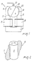
- a typical motor with permanent-magnet rotor is generally designated by the reference numeral 13 in Figure 1, where the rotor is now designated by the reference numeral 14 and is contained between two poles made of laminations 15 and 16 which are the ends of a stator pack 17 whereon two coils 18 and 19 are mounted which induce the stator field.
- the poles In order to be able to privilege one direction of rotation for the rotor, the poles have recesses 20 and 21 which set the axis of symmetry 22 of the rotor 14 at an angle with respect to the median axis of the poles 15 and 16.
- This conventional structure suffers a further problem due to the displacement of the neutral axis of the rotor with respect to the position of the sensor 23.
- the aim of the present invention is to provide a method for the starting and steady-state supply of a permanent-magnet synchronous motor, particularly for driving a centrifugal hydraulic pump, which is capable of overcoming all the proposed problems and in particular of adapting to the problems of each individual motor.
- a consequent primary object is to provide a method which allows to start permanent-magnet synchronous electric motors, even of the medium-power and medium- to high-power types and in a preset direction.
- a consequent primary object is to provide a method for starting and subsequently supplying a permanent-magnet synchronous motor which minimizes the power absorbed during starting and in the steady state.
- Another important object is to provide a method for the steady-state power supply of a permanent-magnet synchronous motor wherein cos ⁇ is practically equal to 1.
- the method according to the invention is composed of three steps, as shown schematically in Figure 3:
- FIG. 3 illustrates a feedback flowchart, described in greater detail hereinafter, which shows that if the rotor slows during the steady-state step, the procedure returns to the starting step, while if the rotor stops or other anomalies occur during the steady-state step the procedure returns to the learning step.
- the rotor is turned through 180 mechanical degrees by applying a low-value DC current on the stator field.
- first of all the procedure determines which minimal current moves the rotor through the first 180° and which current moves it through the second 180°.
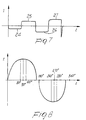
- the linear magnetic position sensor 23 stores a series of values, again in the processor, which correspond to the angular position of the rotor and relate to the first 180 mechanical degrees of rotation and to the subsequent 180 mechanical degrees of rotation, which as a whole form a complete rotation.
- the linear sensor 23 Since the linear sensor 23 is arranged in an intermediate region between the poles of the stator, the value of the magnetic field that it detects is not zero, as it should be in theory, when the rotor is not moving, because, as mentioned, in order to start the rotor in a given direction the poles of the stator 15 and 16 are asymmetrical and are shaped so that the rotor arranges itself with an axial offset angle of approximately 5°, which produces at startup an already-preset imbalance which in addition to allowing the rotor to start more easily also determines its direction of rotation.
- This self-learning step occurs in a very short time which can be approximately 400 milliseconds.
- This self-learning step is performed every time the motor is restarted, so that any modifications or new situations of the motor and of the pump associated therewith are compensated for.
- New situations such as an abnormal load on the impeller, can determine a different starting current at each startup; this is why the learning step is performed every time.
- the motor is supplied every time with the minimum current that is compatible with its movement, reducing consumption and avoiding unnecessary stresses on the stator.
- the learned data yield the values at 90 mechanical degrees; by subtracting approximately 20-25% from this, the procedure obtains the value for which the rotor has covered the first 80 mechanical degrees of its rotation, and this value is repeated at approximately 100 mechanical degrees of rotation.
- the starting step begins when the rotor has arrived at the zero point of the second half-rotation, applying a current which is equal to the starting current determined during the learning step increased by approximately 25% and applied sinusoidally, reconstructing it by means of the power supply circuit controlled by the microprocessor.
- This current is applied and maintained until the rotor has reached the first 180 mechanical degrees, where the procedure waits for it if it is delayed with respect to the preset theoretical time.
- the wait beyond the theoretical time can be conveniently approximately 1.5 seconds.
- This operation is performed for a first complete period; in this way one is certain, with the wait times, to be able to start even high-inertia rotors, since the procedure always waits for the rotor at its transit at the preset angular positions.
- the procedure waits for the rotor exclusively at its transit by the zero point and no longer at intermediate angles.
- the frequency is then increased, again checking the zero point transit of the rotor; in this manner, by increasing or decreasing the set frequency turn by turn according to the longer or shorter waits for the rotor on the zero point, said rotor is gradually brought to the preset steady-state speed.
- the power supply which is an inverter, behaves as a synchronous device, i.e., it is the power supply that adapts to the motion of the rotor rather than the opposite.
- the procedure is returned as if to the starting step, i.e., the inverter reduces the power supply frequency, since it cannot apply a negative half-wave if the positive one has not been completed or if it has not waited for the rotor to reach the zero point.
- the inverter gradually increases the current, accordingly returning the rotor to the frequency that corresponds to the preset speed, albeit under different current conditions.
- the learning procedure is repeated until the motor restarts; if the motor fails to restart because it is jammed, there is a limit for the current which is set in order to determine the starting current.
- Reversal of the sinusoidal curve can be made to occur a short time before the rotor reaches the real zero point.
- the method can be performed using power supplies with circuits of different kinds and also with components of various kinds which are adapted to perform the required operations.
Landscapes
- Engineering & Computer Science (AREA)
- Power Engineering (AREA)
- Control Of Motors That Do Not Use Commutators (AREA)
- Permanent Magnet Type Synchronous Machine (AREA)
- Control Of Positive-Displacement Pumps (AREA)
- Motor And Converter Starters (AREA)
- Control Of Non-Positive-Displacement Pumps (AREA)
- Control Of Ac Motors In General (AREA)
- Lubrication Of Internal Combustion Engines (AREA)
Applications Claiming Priority (3)
| Application Number | Priority Date | Filing Date | Title |
|---|---|---|---|
| IT1998MI001876A IT1301915B1 (it) | 1998-08-07 | 1998-08-07 | Procedimento per l'avviamento e l'alimentazione a regime di un motoresincrono a magneti permanenti particolarmente per l'azionamento di una |
| ITMI981876 | 1998-08-07 | ||
| PCT/EP1999/005554 WO2000008746A1 (en) | 1998-08-07 | 1999-08-02 | Method for the starting and steady-state supply of a permanent-magnet synchronous motor particularly for driving a hydraulic pump |
Publications (2)
| Publication Number | Publication Date |
|---|---|
| EP1020020A1 EP1020020A1 (en) | 2000-07-19 |
| EP1020020B1 true EP1020020B1 (en) | 2004-11-24 |
Family
ID=11380644
Family Applications (1)
| Application Number | Title | Priority Date | Filing Date |
|---|---|---|---|
| EP99941497A Expired - Lifetime EP1020020B1 (en) | 1998-08-07 | 1999-08-02 | Method for the starting and steady-state supply of a permanent-magnet synchronous motor particularly for driving a hydraulic pump |
Country Status (16)
| Country | Link |
|---|---|
| EP (1) | EP1020020B1 (it) |
| JP (1) | JP4271860B2 (it) |
| KR (1) | KR20010024405A (it) |
| CN (1) | CN1160846C (it) |
| AT (1) | ATE283573T1 (it) |
| AU (1) | AU5509199A (it) |
| BR (1) | BR9906688A (it) |
| CA (1) | CA2305457A1 (it) |
| DE (1) | DE69922140T2 (it) |
| ES (1) | ES2233066T3 (it) |
| HU (1) | HUP0004302A3 (it) |
| IL (1) | IL135497A0 (it) |
| IT (1) | IT1301915B1 (it) |
| PL (1) | PL200692B1 (it) |
| RU (1) | RU2222862C2 (it) |
| WO (1) | WO2000008746A1 (it) |
Families Citing this family (10)
| Publication number | Priority date | Publication date | Assignee | Title |
|---|---|---|---|---|
| GB2406004B (en) * | 2003-09-12 | 2005-08-17 | Nicholas Paul Shepherd | Water pump |
| DE10355287B4 (de) * | 2003-11-18 | 2011-04-21 | Dr. Fritz Faulhaber Gmbh & Co. Kg | Ansteuereinrichtung für elektrische Maschinen |
| DE102008029910C5 (de) * | 2008-06-24 | 2020-03-05 | BSH Hausgeräte GmbH | Verfahren zur Lastzustandserkennung einer Pumpe |
| DE102010030239A1 (de) | 2010-06-17 | 2011-12-22 | BSH Bosch und Siemens Hausgeräte GmbH | Verfahren und Vorrichtung zum Anlassen eines Elektromotors |
| CN102751922B (zh) * | 2011-04-19 | 2014-10-29 | 江门市地尔汉宇电器股份有限公司 | 一种微型永磁同步电动机 |
| CN103595322B (zh) * | 2013-11-20 | 2016-10-19 | 南车株洲电力机车研究所有限公司 | 一种永磁同步电机的起动方法及装置 |
| DE102017112485A1 (de) * | 2017-06-07 | 2018-12-13 | Miele & Cie. Kg | Ansteuerung für 1-Phasen-Synchronmotor |
| RU2680287C1 (ru) * | 2018-01-09 | 2019-02-19 | Федеральное Государственное Бюджетное Образовательное Учреждение Высшего Образования "Новосибирский Государственный Технический Университет" | Способ запуска газотурбинного двигателя |
| CN109538462B (zh) * | 2018-11-29 | 2021-01-01 | 江苏江海润液设备有限公司 | 一种立式直流泵的快速启动测试方法 |
| CN112983845B (zh) * | 2021-03-02 | 2023-01-24 | 中核核电运行管理有限公司 | 一种循环水泵正反转检测装置及方法 |
Family Cites Families (6)
| Publication number | Priority date | Publication date | Assignee | Title |
|---|---|---|---|---|
| SU1539950A1 (ru) * | 1987-07-22 | 1990-01-30 | Московский энергетический институт | Устройство дл пуска вентильного электродвигател |
| JP2704057B2 (ja) * | 1991-03-29 | 1998-01-26 | 株式会社東芝 | スピンドルモータの起動制御回路 |
| US5323094A (en) * | 1992-02-24 | 1994-06-21 | Nippon Densen Corporation | Method of starting a sensorless multiphase dc motor |
| RU2079950C1 (ru) * | 1993-08-24 | 1997-05-20 | Научно-производственное предприятие "Эметрон" | Однофазный электродвигатель индукторного типа |
| RU2084074C1 (ru) * | 1994-03-15 | 1997-07-10 | Научно-производственное предприятие "Эметрон" | Схема пуска однофазного индукторного электродвигателя |
| IT1286191B1 (it) * | 1996-08-05 | 1998-07-08 | Tait Srl | Metodo e relativo dispositivo di comando e controllo, in particolare per motori sincroni a magneti permanenti. |
-
1998
- 1998-08-07 IT IT1998MI001876A patent/IT1301915B1/it active IP Right Grant
-
1999
- 1999-08-02 AT AT99941497T patent/ATE283573T1/de not_active IP Right Cessation
- 1999-08-02 ES ES99941497T patent/ES2233066T3/es not_active Expired - Lifetime
- 1999-08-02 CN CNB998013161A patent/CN1160846C/zh not_active Expired - Fee Related
- 1999-08-02 HU HU0004302A patent/HUP0004302A3/hu unknown
- 1999-08-02 JP JP2000564287A patent/JP4271860B2/ja not_active Expired - Fee Related
- 1999-08-02 CA CA002305457A patent/CA2305457A1/en not_active Abandoned
- 1999-08-02 BR BR9906688-2A patent/BR9906688A/pt not_active IP Right Cessation
- 1999-08-02 IL IL13549799A patent/IL135497A0/xx unknown
- 1999-08-02 RU RU2000111468/09A patent/RU2222862C2/ru not_active IP Right Cessation
- 1999-08-02 PL PL339696A patent/PL200692B1/pl not_active IP Right Cessation
- 1999-08-02 KR KR1020007003639A patent/KR20010024405A/ko not_active Withdrawn
- 1999-08-02 AU AU55091/99A patent/AU5509199A/en not_active Abandoned
- 1999-08-02 DE DE69922140T patent/DE69922140T2/de not_active Expired - Lifetime
- 1999-08-02 WO PCT/EP1999/005554 patent/WO2000008746A1/en not_active Ceased
- 1999-08-02 EP EP99941497A patent/EP1020020B1/en not_active Expired - Lifetime
Also Published As
| Publication number | Publication date |
|---|---|
| IL135497A0 (en) | 2001-05-20 |
| WO2000008746A1 (en) | 2000-02-17 |
| DE69922140D1 (de) | 2004-12-30 |
| ATE283573T1 (de) | 2004-12-15 |
| PL339696A1 (en) | 2001-01-02 |
| DE69922140T2 (de) | 2005-12-15 |
| JP4271860B2 (ja) | 2009-06-03 |
| CA2305457A1 (en) | 2000-02-17 |
| CN1275257A (zh) | 2000-11-29 |
| AU5509199A (en) | 2000-02-28 |
| KR20010024405A (ko) | 2001-03-26 |
| ITMI981876A1 (it) | 2000-02-07 |
| ITMI981876A0 (it) | 1998-08-07 |
| EP1020020A1 (en) | 2000-07-19 |
| CN1160846C (zh) | 2004-08-04 |
| IT1301915B1 (it) | 2000-07-07 |
| ES2233066T3 (es) | 2005-06-01 |
| PL200692B1 (pl) | 2009-01-30 |
| HUP0004302A2 (hu) | 2001-04-28 |
| JP2002523007A (ja) | 2002-07-23 |
| HUP0004302A3 (en) | 2001-07-30 |
| BR9906688A (pt) | 2000-08-08 |
| RU2222862C2 (ru) | 2004-01-27 |
Similar Documents
| Publication | Publication Date | Title |
|---|---|---|
| AU2007293764B2 (en) | Control of synchronous electrical machines | |
| EP1020020B1 (en) | Method for the starting and steady-state supply of a permanent-magnet synchronous motor particularly for driving a hydraulic pump | |
| KR20090053019A (ko) | 모터, 세탁기 모터의 제어장치 및 세탁기 모터의 제어방법 | |
| US20190267921A1 (en) | Method for starting up a permanent-magnet synchronous machine, and permanent-magnet synchronous machine | |
| EP3217534B1 (en) | Synchronous electric power distribution startup system | |
| US20190036465A1 (en) | System and method for starting an electric motor | |
| JP2015065730A (ja) | モータの起動制御装置および空気圧縮機 | |
| US6150790A (en) | Method for the starting and steady-state supply of a permanent-magnet synchronous motor particularly for driving a hydraulic pump | |
| RU2543998C1 (ru) | Схема управления синхронным двигателем с постоянными магнитами | |
| RU2000111468A (ru) | Способ электропитания в пусковом и установившемся режимах синхронного двигателя с постоянными магнитами, в частности предназначенного для приведения в движение гидравлического насоса | |
| WO2011090018A1 (ja) | 単相交流同期モータおよびその制御方法 | |
| WO2014156847A1 (ja) | ブラシレスモータの駆動装置及び駆動方法 | |
| JP2001008490A (ja) | 永久磁石式同期電動機の制御装置、及び制御方法 | |
| JP2015065729A (ja) | モータの起動制御装置および空気圧縮機 | |
| RU2103786C1 (ru) | Однофазный электродвигатель со стартовыми полюсами | |
| CZ20001232A3 (cs) | Způsob startování a plynulého napájení synchronního motoru s permanentními magnety zejména pro pohon hydraulického čerpadla | |
| US20230090353A1 (en) | Method for controlling the direction of rotation of a fluid machine and processing unit configured to perform said method | |
| JP2001224198A (ja) | 永久磁石同期モータの起動方法 | |
| WO2018037830A1 (ja) | モータ制御装置 | |
| CN107786127B (zh) | 一种电机的驱动方法及系统 | |
| KR20080094122A (ko) | 센서리스 bldc 모터의 제어 방법 | |
| JP2017034813A (ja) | センサレス・ブラシレスモータの駆動方法及び該駆動方法を用いたモータ制御装置 | |
| JP2017046511A (ja) | モータ駆動装置、およびこれを用いた圧縮機の駆動装置、および冷蔵庫 |
Legal Events
| Date | Code | Title | Description |
|---|---|---|---|
| PUAI | Public reference made under article 153(3) epc to a published international application that has entered the european phase |
Free format text: ORIGINAL CODE: 0009012 |
|
| AK | Designated contracting states |
Kind code of ref document: A1 Designated state(s): AT BE CH CY DE DK ES FI FR GB GR IE IT LI LU MC NL PT SE |
|
| AX | Request for extension of the european patent |
Free format text: AL PAYMENT 20000428;LT PAYMENT 20000428;LV PAYMENT 20000428;MK PAYMENT 20000428;RO PAYMENT 20000428;SI PAYMENT 20000428 |
|
| 17P | Request for examination filed |
Effective date: 20000719 |
|
| GRAP | Despatch of communication of intention to grant a patent |
Free format text: ORIGINAL CODE: EPIDOSNIGR1 |
|
| GRAA | (expected) grant |
Free format text: ORIGINAL CODE: 0009210 |
|
| GRAS | Grant fee paid |
Free format text: ORIGINAL CODE: EPIDOSNIGR3 |
|
| AK | Designated contracting states |
Kind code of ref document: B1 Designated state(s): AT BE CH CY DE DK ES FI FR GB GR IE IT LI LU MC NL PT SE |
|
| AX | Request for extension of the european patent |
Extension state: AL LT LV MK RO SI |
|
| PG25 | Lapsed in a contracting state [announced via postgrant information from national office to epo] |
Ref country code: NL Free format text: LAPSE BECAUSE OF FAILURE TO SUBMIT A TRANSLATION OF THE DESCRIPTION OR TO PAY THE FEE WITHIN THE PRESCRIBED TIME-LIMIT Effective date: 20041124 Ref country code: LI Free format text: LAPSE BECAUSE OF FAILURE TO SUBMIT A TRANSLATION OF THE DESCRIPTION OR TO PAY THE FEE WITHIN THE PRESCRIBED TIME-LIMIT Effective date: 20041124 Ref country code: FI Free format text: LAPSE BECAUSE OF FAILURE TO SUBMIT A TRANSLATION OF THE DESCRIPTION OR TO PAY THE FEE WITHIN THE PRESCRIBED TIME-LIMIT Effective date: 20041124 Ref country code: CH Free format text: LAPSE BECAUSE OF FAILURE TO SUBMIT A TRANSLATION OF THE DESCRIPTION OR TO PAY THE FEE WITHIN THE PRESCRIBED TIME-LIMIT Effective date: 20041124 Ref country code: BE Free format text: LAPSE BECAUSE OF FAILURE TO SUBMIT A TRANSLATION OF THE DESCRIPTION OR TO PAY THE FEE WITHIN THE PRESCRIBED TIME-LIMIT Effective date: 20041124 Ref country code: AT Free format text: LAPSE BECAUSE OF FAILURE TO SUBMIT A TRANSLATION OF THE DESCRIPTION OR TO PAY THE FEE WITHIN THE PRESCRIBED TIME-LIMIT Effective date: 20041124 |
|
| REG | Reference to a national code |
Ref country code: GB Ref legal event code: FG4D |
|
| REG | Reference to a national code |
Ref country code: CH Ref legal event code: EP |
|
| REF | Corresponds to: |
Ref document number: 69922140 Country of ref document: DE Date of ref document: 20041230 Kind code of ref document: P |
|
| REG | Reference to a national code |
Ref country code: IE Ref legal event code: FG4D |
|
| PG25 | Lapsed in a contracting state [announced via postgrant information from national office to epo] |
Ref country code: SE Free format text: LAPSE BECAUSE OF FAILURE TO SUBMIT A TRANSLATION OF THE DESCRIPTION OR TO PAY THE FEE WITHIN THE PRESCRIBED TIME-LIMIT Effective date: 20050224 Ref country code: GR Free format text: LAPSE BECAUSE OF FAILURE TO SUBMIT A TRANSLATION OF THE DESCRIPTION OR TO PAY THE FEE WITHIN THE PRESCRIBED TIME-LIMIT Effective date: 20050224 Ref country code: DK Free format text: LAPSE BECAUSE OF FAILURE TO SUBMIT A TRANSLATION OF THE DESCRIPTION OR TO PAY THE FEE WITHIN THE PRESCRIBED TIME-LIMIT Effective date: 20050224 |
|
| LTIE | Lt: invalidation of european patent or patent extension |
Effective date: 20041124 |
|
| NLV1 | Nl: lapsed or annulled due to failure to fulfill the requirements of art. 29p and 29m of the patents act | ||
| REG | Reference to a national code |
Ref country code: CH Ref legal event code: PL |
|
| REG | Reference to a national code |
Ref country code: ES Ref legal event code: FG2A Ref document number: 2233066 Country of ref document: ES Kind code of ref document: T3 |
|
| PG25 | Lapsed in a contracting state [announced via postgrant information from national office to epo] |
Ref country code: LU Free format text: LAPSE BECAUSE OF NON-PAYMENT OF DUE FEES Effective date: 20050802 Ref country code: IE Free format text: LAPSE BECAUSE OF NON-PAYMENT OF DUE FEES Effective date: 20050802 Ref country code: CY Free format text: LAPSE BECAUSE OF FAILURE TO SUBMIT A TRANSLATION OF THE DESCRIPTION OR TO PAY THE FEE WITHIN THE PRESCRIBED TIME-LIMIT Effective date: 20050802 |
|
| ET | Fr: translation filed | ||
| PG25 | Lapsed in a contracting state [announced via postgrant information from national office to epo] |
Ref country code: MC Free format text: LAPSE BECAUSE OF NON-PAYMENT OF DUE FEES Effective date: 20050831 |
|
| PLBE | No opposition filed within time limit |
Free format text: ORIGINAL CODE: 0009261 |
|
| STAA | Information on the status of an ep patent application or granted ep patent |
Free format text: STATUS: NO OPPOSITION FILED WITHIN TIME LIMIT |
|
| 26N | No opposition filed |
Effective date: 20050825 |
|
| REG | Reference to a national code |
Ref country code: IE Ref legal event code: MM4A |
|
| PG25 | Lapsed in a contracting state [announced via postgrant information from national office to epo] |
Ref country code: PT Free format text: LAPSE BECAUSE OF NON-PAYMENT OF DUE FEES Effective date: 20050424 |
|
| PGFP | Annual fee paid to national office [announced via postgrant information from national office to epo] |
Ref country code: ES Payment date: 20080708 Year of fee payment: 10 Ref country code: DE Payment date: 20080828 Year of fee payment: 10 |
|
| PGFP | Annual fee paid to national office [announced via postgrant information from national office to epo] |
Ref country code: IT Payment date: 20080829 Year of fee payment: 10 Ref country code: FR Payment date: 20080718 Year of fee payment: 10 |
|
| PGFP | Annual fee paid to national office [announced via postgrant information from national office to epo] |
Ref country code: GB Payment date: 20080813 Year of fee payment: 10 |
|
| GBPC | Gb: european patent ceased through non-payment of renewal fee |
Effective date: 20090802 |
|
| REG | Reference to a national code |
Ref country code: FR Ref legal event code: ST Effective date: 20100430 |
|
| PG25 | Lapsed in a contracting state [announced via postgrant information from national office to epo] |
Ref country code: DE Free format text: LAPSE BECAUSE OF THE APPLICANT RENOUNCES Effective date: 20100121 |
|
| PG25 | Lapsed in a contracting state [announced via postgrant information from national office to epo] |
Ref country code: FR Free format text: LAPSE BECAUSE OF NON-PAYMENT OF DUE FEES Effective date: 20090831 |
|
| REG | Reference to a national code |
Ref country code: ES Ref legal event code: FD2A Effective date: 20090803 |
|
| PG25 | Lapsed in a contracting state [announced via postgrant information from national office to epo] |
Ref country code: GB Free format text: LAPSE BECAUSE OF NON-PAYMENT OF DUE FEES Effective date: 20090802 |
|
| PG25 | Lapsed in a contracting state [announced via postgrant information from national office to epo] |
Ref country code: IT Free format text: LAPSE BECAUSE OF NON-PAYMENT OF DUE FEES Effective date: 20090802 |
|
| PG25 | Lapsed in a contracting state [announced via postgrant information from national office to epo] |
Ref country code: ES Free format text: LAPSE BECAUSE OF NON-PAYMENT OF DUE FEES Effective date: 20090803 |