EP1020137B1 - Arrangement pour une table ayant au moins deux surfaces de table - Google Patents
Arrangement pour une table ayant au moins deux surfaces de table Download PDFInfo
- Publication number
- EP1020137B1 EP1020137B1 EP99119152A EP99119152A EP1020137B1 EP 1020137 B1 EP1020137 B1 EP 1020137B1 EP 99119152 A EP99119152 A EP 99119152A EP 99119152 A EP99119152 A EP 99119152A EP 1020137 B1 EP1020137 B1 EP 1020137B1
- Authority
- EP
- European Patent Office
- Prior art keywords
- column
- control plate
- arrangement according
- base
- table arrangement
- Prior art date
- Legal status (The legal status is an assumption and is not a legal conclusion. Google has not performed a legal analysis and makes no representation as to the accuracy of the status listed.)
- Expired - Lifetime
Links
- 238000013016 damping Methods 0.000 claims description 7
- 229910000639 Spring steel Inorganic materials 0.000 claims description 4
- 230000000149 penetrating effect Effects 0.000 claims description 2
- NJPPVKZQTLUDBO-UHFFFAOYSA-N novaluron Chemical compound C1=C(Cl)C(OC(F)(F)C(OC(F)(F)F)F)=CC=C1NC(=O)NC(=O)C1=C(F)C=CC=C1F NJPPVKZQTLUDBO-UHFFFAOYSA-N 0.000 claims 3
- 230000001360 synchronised effect Effects 0.000 claims 1
- 230000005540 biological transmission Effects 0.000 abstract description 6
- 230000033001 locomotion Effects 0.000 description 20
- 229920001971 elastomer Polymers 0.000 description 2
- 239000011521 glass Substances 0.000 description 2
- 238000010521 absorption reaction Methods 0.000 description 1
- 238000004026 adhesive bonding Methods 0.000 description 1
- 230000000694 effects Effects 0.000 description 1
- 239000000806 elastomer Substances 0.000 description 1
- 230000035939 shock Effects 0.000 description 1
- 230000007704 transition Effects 0.000 description 1
Images


Classifications
-
- A—HUMAN NECESSITIES
- A47—FURNITURE; DOMESTIC ARTICLES OR APPLIANCES; COFFEE MILLS; SPICE MILLS; SUCTION CLEANERS IN GENERAL
- A47B—TABLES; DESKS; OFFICE FURNITURE; CABINETS; DRAWERS; GENERAL DETAILS OF FURNITURE
- A47B13/00—Details of tables or desks
- A47B13/08—Table tops; Rims therefor
- A47B13/088—Sectional table tops
-
- A—HUMAN NECESSITIES
- A47—FURNITURE; DOMESTIC ARTICLES OR APPLIANCES; COFFEE MILLS; SPICE MILLS; SUCTION CLEANERS IN GENERAL
- A47B—TABLES; DESKS; OFFICE FURNITURE; CABINETS; DRAWERS; GENERAL DETAILS OF FURNITURE
- A47B11/00—Tables with tops revolvable on vertical spindles
Definitions
- the invention relates to a table arrangement with at least two table tops, each rotatable by means of a table column stored and by a crank mechanism kinematics are in particular synchronously coupled to one another, wherein each table column in the manner of a crank arm Hinge point is assigned by a dimensionally stable transmission element are interconnected.
- Such a table arrangement is known from DE 91 04 982 U and DE 297 00 300 U1.
- the table arrangement has two table tops that in each case by a pivotable on a common base stored, vertical table column are worn.
- To one enable simultaneous movement of both table tops are the two swiveling table columns via a crank mechanism coupled synchronously.
- everyone is there Table column assigned a rocker arm, which by an as Crank transmission element serving crank rod motion transmitting are coupled together.
- the table columns are Stops assigned by means of which the swivel angle of the Table columns and the crank mechanism is limited to 90 °.
- the Swiveling movements are so on the position of the rectangular Tabletops designed that are in the opposite End positions the table tops to different sizes Complete overall contours.
- the object of the invention is a table arrangement of the beginning mentioned type to create improved functionality having.
- each table column in one stationary column base and at least one relative to that Column base rotatable column part is divided, and that each rotating column part over two parallel to each other offset axes of rotation with the stationary column base on the one hand and with at least one parallel to the table tops, on the other hand serving as a transmission element control plate is rotatably connected.
- the control plate can have a double function take over by firstly a storage space the table arrangement forms and on the other an essential Part of the crank mechanism-like kinematics for the common Rotary movement of the table tops represents.
- the level Relocation or control movement of the control plate at one Rotation of the table tops is relatively small, so that the Control plate harmless as a footprint especially for the filing of books or magazines can be used.
- the size of the shift movement depends on the lever arms of the rotary axis distances serving as crank arms are preferably of the same length to create However, step-up or step-down ratios also differ can be dimensioned. Define the lever arms by the distance between the two axes of rotation of the respective Column part. In principle, it is also possible, in particular at least two control plates arranged one above the other to provide the crank arms so offset from each other are assigned that the table tops are also complete Can perform revolutions without dead center to get.
- the second control plate that moves the to the first pair of crank arms arranged crank arms couples with each other, is preferably articulated at such an angle, that the existing with a single control plate Dead center is compensated for at full revolutions.
- the at least one control plate can be both above and be positioned below the table tops.
- the pillar feet of the table columns, opposite the rotating column parts are stationary, can only be cone-like Axes of rotation or as tubular or sleeve-like mounts be designed.
- the rotating column part of each table column can in turn once again in at least two firmly together connected column parts can be divided.
- the connection between the two column parts then preferably takes place through an eccentric crank pin that defines the axis of rotation forms in the area of the control plate.
- the one column part ends below the control plate and the other above the control plate begins, it is possible to pass through to keep it relatively small in the control plate. In the same way however, it is also possible to get one through the control plate penetrating, continuous rotatable column part to be provided for each table column. In this case they are Passage areas in the control plate are correspondingly larger designed. In addition, the passage area is at its edge a point over a pivot point forming the axis of rotation connected to the column part.
- the stationary column feet assigned to a common base This is a special one simple design, since only a single base must be provided, the all stationary column feet Forms table columns.
- this is at least a control plate designed at least partially transparent.
- the control plate is preferably designed to be completely transparent and made of glass. This configuration is in Visually particularly impressive, because not without further recognizable is how the synchronization of the two Table tops to each other is realized.
- they are the control plate column parts flanking the top and bottom by means of a to the axis of rotation of the table column of eccentric crank pins with each other connected to the control plate at a bearing penetrates.
- the crank pin that serves as the pivot point is thus aligned parallel to the axis of rotation of the table column and creates a particularly simple and secure connection with the control plate that is preferably invisible between the two coaxially aligned, upper and lower Column parts are covered.
- the bearing is designed as a passage in which a roller or plain bearing is positioned.
- a further embodiment is a lower one Column part of each table column using a roller or plain bearing rotatably mounted on the base.
- the stop device by an axially aligned stop pin on the one hand and a circular arc guide on the other hand formed, the stop pin the rotatable Column part or the base and the backdrop guide accordingly vice versa assigned to the base or the column part are. This will ensure that the Swiveling movement of the table columns and thus the table tops to the desired swivel angle amount, preferably to one Swivel angle of 90 ° achieved.
- the stop pin by means of an elastically flexible damping jacket in the base or the column part.
- the stop pin made of spring steel and is in one for the backdrop guide distal end portion precisely fitted in the column part or base held and interspersed in one of the scenery guides facing section with radial clearance a extended recording.
- the pin-shaped stop pin made of spring steel is therefore precise and precise in its end area a correspondingly precisely created hole. in the further course of the stop pin is due to the extended Provide the receptacle with a clearance, which makes the springy and damping effect of the stop pin in particular is achieved in a simple manner. An additional damping jacket can therefore advantageously be avoided.
- all have a common one Control plate associated pivot points relative to identical axis of rotation of the associated column part Angular positions.
- the control plate can be any Have contours.
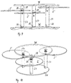
- a table arrangement 1 according to FIGS. 1 to 4 has two table tops 2a, 2b, which are each fixed on a pivotable table column 3a, 3b.
- the table columns 3a, 3b are mounted in the manner described in more detail below by means of a base foot 6 on a common, plate-shaped table base around a vertical axis of rotation S 1 .
- the two pivotable table columns 3a, 3b are synchronously coupled to one another in the manner also described below by means of a crank mechanism, a control plate 4 arranged parallel to the table tops 2a, 2b being provided as the crank transmission element.
- the pivoting mobility of the two table tops 2a, 2b is limited to a pivoting angle of 90 °, so that the positioning of the table tops 2a, 2b in FIGS. 1 and 3 represent the opposite end positions.
- the table arrangement corresponds to a table arrangement as described in DE 297 00 300 U1, so that for a more detailed explanation of the disclosure in this publication is referred to.
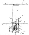
- each table column 3a, 3b according to FIG. 4 is divided into two column parts 7, 8 arranged coaxially one above the other, between which the control plate 4 is movably mounted in a plane parallel to the table plates 2a, 2b ,
- the control plate 4 represents a common connecting element between the two table columns 3a, 3b and is also - like the base plate 5 - rectangular.
- the two column parts 7, 8 are connected to one another via a crank pin 9 which is aligned eccentrically to the axis of rotation S 1 and with a parallel axis of rotation S 2 and which penetrates the control plate 4 in the region of an unspecified passage.
- the passage is additionally provided with a ball bearing 10, which is only shown schematically.
- crank pin 9 is preferably fixed by gluing.
- the end faces of the column parts 7 facing the upper side and the lower side of the control plate 4 are provided with sliding disks 11, which enable the control plate 4 to move relatively smoothly between the two column parts 7, 8.
- the upper column part 7 carries the assigned table top 2a or 2b, the table top being releasably fixed on the column part 7 for assembly reasons.
- the lower column part 8 is designed like a sleeve and is mounted on a bearing pin 12 of the base foot 6, which is aligned coaxially with the axis of rotation S 1 and is firmly connected to the base plate 5.
- a roller bearing 13 is provided for mounting the column part 8 on the bearing journal 12, which is fixed axially relative to the bearing journal 12 by means of a locking ring 14, which also axially secures the column part.
- a circular arc-shaped, upwardly open groove 17 is provided in at least one base foot 6, preferably in both base feet 6, which runs concentrically to the axis of rotation S 1 .
- the groove 17 describes a quarter circle.
- a stop pin 15 engages in the groove, which is aligned axially parallel to the pivot axis S and is positioned in a corresponding receptacle of the lower column part 8 which is open at the bottom.
- the stop pin 15 is held in the receptacle by means of a damping jacket in the form of a rubber or elastomer sleeve 16, so that the stop pin 15 is elastically flexible to a small extent in all directions. This results in a constant damping of the stop pin 15 in its end positions over a long period of time.
- both are Table tops 2a, 2b as well as the control plate 4 and the base plate 5 made of glass, so that there is a transparent Table arrangement results. Since the control plate 4 only makes slight, level movements corresponding movements of the control plate 4 not easily recognizable, so that in a visually stunning manner when one of the table tops 2a or 2b is rotated synchronously the other table top is also moved.
- the based 1 to 4 table arrangement shown is particularly can be used as a coffee table, the two table tops in different heights are positioned to each other, however arranged at the same height depending on the dimensions could be.
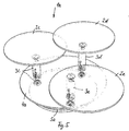
- Table 5 has three round table tops 2c to 2e, each of a table column 3c to 3e are worn.
- the table columns 3c to 3e are except for the stop device 7 executed.
- the table tops 2c to 2e can be rotated through 360 ° without a stop.
- Essential for such smooth movement of the control plate 4a is that all as articulation points between the control plate 4a and the column parts of the table columns 3c to 3e running crank pins 9a (Fig. 7) in an identical angular position to the respective Axis of rotation of the associated table column 3c to 3e positioned are.
- the lever arms between the respective axis of rotation and the Articulation point, i.e. the respective crank pin, are therefore always aligned parallel to each other.
- the table columns 3c to 3e correspond to the table column Fig. 7 as well as the table column of FIG. 4, but in each case with the difference that no anchor device is provided is because the table tops 2c to 2e are rotated without a stop can.
- the anchor device can in a simple manner 7 are removed in that the pin-shaped stop pin 20 is removed.
- the crank pin 9a in the table column according to FIG. 7 is a stepped bolt designed, being in the passage area of the control plate has the largest diameter, because here the greatest loads occur.
- a stop device may be provided must, so is the anchor device shown in Fig. 7 the table column 3'a, 3'b, 3c, 3d, 3e particularly simple and designed to be reliable.
- this anchor device only a pin-shaped stop pin 20 made of spring steel provided that in a stepped, vertical bore 21, 22nd is used.
- An upper end region 21 of the bore is exact on the diameter or dimensions of the stop pin 20 matched.
- the upper end region 21 thus forms either a transition or press fit for the stop pin 20.
- the stop pin is 20th additionally glued into the end region 21 to ensure a secure To achieve support in the end region 21.
- the lower Part of the bore is an enlarged receptacle 22 that forms a clearance for the stop pin 20. With his the lower end region protrudes accordingly 4 in an arcuate backdrop guide 23 in. Through the clearance in the area of the extended Recording 22 is a resilient evasion of the stop pin 20 possible. This will make it incredibly easier One way is an exact stop and the other one achieved reliable damping.
- a stop device is not for use with a table arrangement limited according to the exemplary embodiments described, but can be used identically in all other areas be used, the appropriate movement stops need.
- the link guide 23 is stationary Column base 6 of the table column housed, whereas the stop pin 20 positioned in the rotating column part is. In the same way, however, an inverted arrangement can also be used be provided.
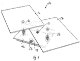
- the table arrangement 1c two table tops 2f, 2g, each on one by the one-piece column part passing through the control plate 4c 3f, 3g are held.
- the rotatable column parts 3f, 3g are rotatably supported in a sleeve-like column base, where both pillar feet part of a common base plate 5c are.
- There is a large passage in the control plate 4c 24 is provided for each column part 3f, 3g, the larger is the cross section of the respective column part 3f, 3g.
- the passage 24 has a kidney-like free cross section on that on the shifting movement of the control plate 4c matched during the rotary movement of the table tops 2f, 2g is.
- the control plate 4c is in the edge area of both Passages 24 by means of one each with one to the column axis of rotation parallel pivot axis provided pivot point 25 connected to the respective column part 3f, 3g, by a simple, radial to the axis of rotation of the column part 3f, 3g aligned pin connection are created can.
- the rotary, i.e. Swiveling movement of the table tops 2f, 2g is limited to approximately 90 ° in this exemplary embodiment.
- kidney-shaped passages 24 to cover is in a simple manner a disc-shaped Aperture 26 concentric to the column parts 3f, 3g over the each passage 24 placed.
- the apertures 26 are only on the control plate 4c without being firmly connected to it to be.
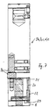
- the table arrangement according to FIGS. 9 and 10 has three round ones Table tops 2 ', each using a vertical Table column 27 to 29 horizontally rotatable in different Levels are stored.
- a base plate 5d is provided on the bottom.
- one continuous base plate 5d can also be a Arrangement of three base feet may be provided, which are independent stand up from each other on the ground.
- the rotatable column parts 27 are each eccentric offset, vertical axis of rotation by means of eccentric, Serving as pivot points pivot pin 26 stored on the base plate 5d.
- Each pillar part 27 is in the end as a pillar section 28 designed bearing section coaxial to a central one Central longitudinal axis of each table column and thus axially offset rotatably mounted to the axis of rotation of the journal 26.
- a bearing 29 is provided, which among other things one coaxially in a corresponding face hole of the column part 27 has protruding pins.
- each Table column is with its upper face on a bottom a control plate 4d fixed, preferably glued.
- the control plate moves, by means of the column sections 28 and the bearings 29 is connected to the column parts 27, with a corresponding Rotational movement of the table tops 2 'slightly a horizontal plane as defined by the distances of the Axes of rotation of the journals 26 and the bearings 29 to one another defined crank movements.
- it is necessary that defined by the distances of the respective axes of rotation Lever arms are aligned parallel to each other and thus have the same angular orientation.
- the table arrangement according to FIGS. 9 and 10 works in the same way if the table arrangement is turned over and the control plate 4d with its top according to FIG. 9 on the Surface rests.
- the base plate 5d as a control plate, which the actuation movement makes, whereas the original control plate 5d remains stationary as a base plate.
Landscapes
- Accommodation For Nursing Or Treatment Tables (AREA)
- Catching Or Destruction (AREA)
- Agricultural Chemicals And Associated Chemicals (AREA)
- Apparatus For Radiation Diagnosis (AREA)
- Tables And Desks Characterized By Structural Shape (AREA)
Claims (12)
- Agencement de table avec au moins deux plateaux, tournant chacun autour d'un montant de table, et couplés entre eux et plus particulièrement de façon synchrone par une cinématique de type mécanisme à bielle et manivelle, chaque montant de table étant associé selon le principe d'une bielle à un point d'articulation différent, reliés ensemble par un élément de transmission indéformable où chaque montant de table (3a, 3b, 3'a, 3'b, 3c, 3d, 3e, 3f, 3g, 26 à 28) est divisé en un pied fixe (6, 26) et au moins une partie de montant mobile en rotation (7, 8, 27, 28) par rapport au pied fixe (6, 26), caractérisé par le fait que chaque partie de montant mobile en rotation (7, 8, 27, 28) est reliée de façon mobile en rotation par deux axes de rotation décalés parallèlement (S1, S2) au pied de montant fixe (6, 26) d'une part et à au moins un plateau de commande (4 à 4d) servant d'élément de transmission placé parallèlement aux plateaux (2a à 2g, 2'), d'autre part.
- Agencement de table selon la revendication 1 caractérisé par le fait que les pieds de montant fixes sont regroupés sur un socle commun (5 à 5d).
- Agencement de table selon la revendication 1 caractérisé par le fait qu'au moins un plateau de commande (4 à 4d) a une structure au moins partiellement transparente.
- Agencement de table selon la revendication 1 ou 2 caractérisé par le fait que l'angle de pivotement du mécanisme à bielle et manivelle (7, 8, 9, 4) est limité par un dispositif de butée mécanique (15 à 17) ― de préférence à un angle de pivotement de 90°.
- Agencement de table selon la revendication 1 ou 2 caractérisé par le fait que les parties du montant (7, 8) jouxtant en haut et en bas le plateau de commande (4) sont reliées à l'aide d'un maneton (9) excentrique par rapport à l'axe de rotation (S1) du montant de table (3a, 3b), qui pénètre dans le plateau de commande (4) au niveau d'un point d'appui.
- Agencement de table selon la revendication 5 caractérisé par le fait que le point d'appui est traversant et accueille un roulement ou un palier lisse (10).
- Agencement de table selon l'une des revendications précédentes caractérisé par le fait qu'une partie inférieure (8) de chaque montant de table (3a, 3b) est montée de façon rotative sur le socle (6) à l'aide d'un roulement ou d'un palier lisse (13).
- Agencement de table selon la revendication 4 caractérisé par le fait que le dispositif de butée mécanique ( 15 à 17) est formé d'une part d'un tenon orienté axialement (15) et d'autre part d'un guide de coulisse en forme d'arc de cercle (17), le tenon (15) étant associé à la partie de montant mobile (8) et le guide de coulisse (17) au socle (6), ou inversement.
- Agencement de table selon la revendication 8 caractérisé par le fait que le tenon (15) est positionné à l'aide d'une gaine d'amortissement souple et élastique (16) dans le socle ou la partie de montant (8).
- Agencement de table selon la revendication 8 caractérisé par le fait que le tenon (20) est fabriqué en acier à ressort et est maintenu dans une extrémité ajustée avec précision dans la partie de montant ou le socle comme guide de coulisse (23), et traverse, avec un jeu radial, un logement élargi (22) dans une partie orientée vers le guide de coulisse (23).
- Agencement d e table s elon la r evendication 1 c aractérisé parle fait que tous les points d'articulation associés à un plateau de commande commun (4a, 4b) présentent des positions angulaires identiques par rapport à l'axe de rotation concerné de la partie de montant correspondante (3c à 3e, 3'a, 3'b, 18, 19).
- Agencement de table selon la revendication 11 caractérisé par le fait qu'au moins trois points d'articulation, distants entre eux et situés dans un même plan, sont couplés à un nombre correspondant de parties de montant par un plateau de commande commun.
Applications Claiming Priority (2)
| Application Number | Priority Date | Filing Date | Title |
|---|---|---|---|
| DE19901369 | 1999-01-15 | ||
| DE19901369A DE19901369C2 (de) | 1999-01-15 | 1999-01-15 | Tischanordnung mit wenigstens zwei Tischplatten |
Publications (3)
| Publication Number | Publication Date |
|---|---|
| EP1020137A2 EP1020137A2 (fr) | 2000-07-19 |
| EP1020137A3 EP1020137A3 (fr) | 2000-08-16 |
| EP1020137B1 true EP1020137B1 (fr) | 2003-12-10 |
Family
ID=7894356
Family Applications (1)
| Application Number | Title | Priority Date | Filing Date |
|---|---|---|---|
| EP99119152A Expired - Lifetime EP1020137B1 (fr) | 1999-01-15 | 1999-10-05 | Arrangement pour une table ayant au moins deux surfaces de table |
Country Status (3)
| Country | Link |
|---|---|
| EP (1) | EP1020137B1 (fr) |
| AT (1) | ATE255830T1 (fr) |
| DE (2) | DE19901369C2 (fr) |
Cited By (1)
| Publication number | Priority date | Publication date | Assignee | Title |
|---|---|---|---|---|
| JP2009066040A (ja) * | 2007-09-11 | 2009-04-02 | Okayama Univ | ウジムシ治療用のカバードレッシング |
Families Citing this family (4)
| Publication number | Priority date | Publication date | Assignee | Title |
|---|---|---|---|---|
| ATE262296T1 (de) * | 2001-01-12 | 2004-04-15 | Matthias Fischer Design Gmbh | Tischanordnung mit wenigstens zwei tischplatten |
| DE10150397A1 (de) * | 2001-10-05 | 2003-04-17 | Matthias Fischer | Tischanordnung mit wenigstens zwei Tischplatten |
| DE10102401B4 (de) * | 2001-01-12 | 2005-02-03 | Matthias Fischer Design Gmbh | Tischanordnung mit wenigstens zwei Tischplatten |
| EP1285603A1 (fr) * | 2001-08-13 | 2003-02-26 | Robert Daniel Pike | Table |
Family Cites Families (5)
| Publication number | Priority date | Publication date | Assignee | Title |
|---|---|---|---|---|
| DE2456769A1 (de) * | 1974-11-30 | 1976-08-12 | Werner Schramm | Praesentierstaender zur sortierten zurschaustellung von waren |
| DE9104982U1 (de) * | 1991-04-23 | 1991-06-13 | Alfons Venjakob GmbH & Co KG, 4830 Gütersloh | Couchtisch |
| DE9105020U1 (de) * | 1991-04-24 | 1991-06-06 | Alfons Venjakob GmbH & Co KG, 4830 Gütersloh | Couchtisch mit zwei Tischplatten |
| DE19700538C2 (de) * | 1997-01-10 | 1999-09-02 | Fischer | Möbelstück mit wenigstens zwei exzentrisch drehbar gelagerten Platten |
| DE29700300U1 (de) * | 1997-01-10 | 1997-02-27 | Fischer, Matthias, Dipl.-Designer, 60325 Frankfurt | Tischanordnung mit zwei Tischplatten |
-
1999
- 1999-01-15 DE DE19901369A patent/DE19901369C2/de not_active Expired - Fee Related
- 1999-10-05 EP EP99119152A patent/EP1020137B1/fr not_active Expired - Lifetime
- 1999-10-05 DE DE59908018T patent/DE59908018D1/de not_active Expired - Lifetime
- 1999-10-05 AT AT99119152T patent/ATE255830T1/de not_active IP Right Cessation
Cited By (1)
| Publication number | Priority date | Publication date | Assignee | Title |
|---|---|---|---|---|
| JP2009066040A (ja) * | 2007-09-11 | 2009-04-02 | Okayama Univ | ウジムシ治療用のカバードレッシング |
Also Published As
| Publication number | Publication date |
|---|---|
| DE19901369A1 (de) | 2000-07-27 |
| DE59908018D1 (de) | 2004-01-22 |
| EP1020137A3 (fr) | 2000-08-16 |
| ATE255830T1 (de) | 2003-12-15 |
| DE19901369C2 (de) | 2002-11-07 |
| EP1020137A2 (fr) | 2000-07-19 |
Similar Documents
| Publication | Publication Date | Title |
|---|---|---|
| DE3512201C2 (fr) | ||
| DE3815450A1 (de) | Weitwinkel-scharnier mit zahnrad-getriebe | |
| EP1020137B1 (fr) | Arrangement pour une table ayant au moins deux surfaces de table | |
| DE102020101309A1 (de) | Armlehne, insbesondere für einen Bürostuhl | |
| DE102018114207B3 (de) | Virtuelle Schwenkvorrichtung mit Bewegungsbegrenzung | |
| EP0953127B1 (fr) | Element articule pour support | |
| DE3873922T2 (de) | Tische. | |
| EP1222876B1 (fr) | Arrangement pour une table ayant au moins deux plateaux | |
| DE8814976U1 (de) | Spielzeugpuppe | |
| EP1785057B1 (fr) | Table à au moins deux plateaux | |
| DE3740004C2 (fr) | ||
| EP0783851B1 (fr) | Table à rallonge équipér de deux éléments de panneau | |
| DE29620168U1 (de) | Matratzenrahmen mit einem in der Neigung einstellbaren Rückenstützteil und Nackenstützteil | |
| EP1050245A2 (fr) | Placard de coin avec un support pour un carrousel | |
| DE10102401B4 (de) | Tischanordnung mit wenigstens zwei Tischplatten | |
| DE1114290B (de) | Hubvorrichtung fuer einen in der Hoehe verstellbaren Tisch | |
| DE3400814C2 (de) | Antriebsmechanismus für eine Spielfigurengruppe | |
| DE19845510C1 (de) | Tischanordnung mit wenigstens zwei gelenkig miteinander verbundenen Tischteilen | |
| EP1787547A1 (fr) | Piece de mobilier á panneau variable | |
| DE1804463C3 (de) | Mikroskop | |
| DE2846144C2 (de) | Vorrichtung zum lösbaren Befestigen von Reinigungsgeräten | |
| DE4105745B4 (de) | Arbeitspult, insbesondere Schreibtisch | |
| DE10102400A1 (de) | Tischanordnung mit wenigstens zwei Tischplatten | |
| EP1040771A2 (fr) | Parapluie | |
| DE19946138A1 (de) | Scharnier mit Einrastung für einen Klapptisch |
Legal Events
| Date | Code | Title | Description |
|---|---|---|---|
| PUAI | Public reference made under article 153(3) epc to a published international application that has entered the european phase |
Free format text: ORIGINAL CODE: 0009012 |
|
| PUAL | Search report despatched |
Free format text: ORIGINAL CODE: 0009013 |
|
| AK | Designated contracting states |
Kind code of ref document: A2 Designated state(s): AT BE CH CY DE DK ES FI FR GB GR IE IT LI LU MC NL PT SE |
|
| AX | Request for extension of the european patent |
Free format text: AL;LT;LV;MK;RO;SI |
|
| AK | Designated contracting states |
Kind code of ref document: A3 Designated state(s): AT BE CH CY DE DK ES FI FR GB GR IE IT LI LU MC NL PT SE |
|
| AX | Request for extension of the european patent |
Free format text: AL;LT;LV;MK;RO;SI |
|
| 17P | Request for examination filed |
Effective date: 20010125 |
|
| AKX | Designation fees paid |
Free format text: AT BE CH CY DE DK ES FI FR GB GR IE IT LI LU MC NL PT SE |
|
| RAP1 | Party data changed (applicant data changed or rights of an application transferred) |
Owner name: MATTHIAS FISCHER DESIGN GMBH |
|
| RIN1 | Information on inventor provided before grant (corrected) |
Inventor name: MATTHIAS FISCHER DESIGN GMBH |
|
| RIN1 | Information on inventor provided before grant (corrected) |
Inventor name: FISCHER, MATTHIAS, DIPL.-DESIGNER |
|
| GRAH | Despatch of communication of intention to grant a patent |
Free format text: ORIGINAL CODE: EPIDOS IGRA |
|
| GRAS | Grant fee paid |
Free format text: ORIGINAL CODE: EPIDOSNIGR3 |
|
| GRAA | (expected) grant |
Free format text: ORIGINAL CODE: 0009210 |
|
| AK | Designated contracting states |
Kind code of ref document: B1 Designated state(s): AT BE CH CY DE DK ES FI FR GB GR IE IT LI LU MC NL PT SE |
|
| PG25 | Lapsed in a contracting state [announced via postgrant information from national office to epo] |
Ref country code: IE Free format text: LAPSE BECAUSE OF FAILURE TO SUBMIT A TRANSLATION OF THE DESCRIPTION OR TO PAY THE FEE WITHIN THE PRESCRIBED TIME-LIMIT Effective date: 20031210 Ref country code: FI Free format text: LAPSE BECAUSE OF FAILURE TO SUBMIT A TRANSLATION OF THE DESCRIPTION OR TO PAY THE FEE WITHIN THE PRESCRIBED TIME-LIMIT Effective date: 20031210 Ref country code: CY Free format text: LAPSE BECAUSE OF FAILURE TO SUBMIT A TRANSLATION OF THE DESCRIPTION OR TO PAY THE FEE WITHIN THE PRESCRIBED TIME-LIMIT Effective date: 20031210 |
|
| REG | Reference to a national code |
Ref country code: GB Ref legal event code: FG4D Free format text: NOT ENGLISH |
|
| REG | Reference to a national code |
Ref country code: CH Ref legal event code: EP |
|
| REG | Reference to a national code |
Ref country code: IE Ref legal event code: FG4D Free format text: GERMAN |
|
| REF | Corresponds to: |
Ref document number: 59908018 Country of ref document: DE Date of ref document: 20040122 Kind code of ref document: P |
|
| REG | Reference to a national code |
Ref country code: CH Ref legal event code: NV Representative=s name: ZIMMERLI, WAGNER & PARTNER AG |
|
| PG25 | Lapsed in a contracting state [announced via postgrant information from national office to epo] |
Ref country code: SE Free format text: LAPSE BECAUSE OF FAILURE TO SUBMIT A TRANSLATION OF THE DESCRIPTION OR TO PAY THE FEE WITHIN THE PRESCRIBED TIME-LIMIT Effective date: 20040310 Ref country code: GR Free format text: LAPSE BECAUSE OF FAILURE TO SUBMIT A TRANSLATION OF THE DESCRIPTION OR TO PAY THE FEE WITHIN THE PRESCRIBED TIME-LIMIT Effective date: 20040310 Ref country code: DK Free format text: LAPSE BECAUSE OF FAILURE TO SUBMIT A TRANSLATION OF THE DESCRIPTION OR TO PAY THE FEE WITHIN THE PRESCRIBED TIME-LIMIT Effective date: 20040310 |
|
| PG25 | Lapsed in a contracting state [announced via postgrant information from national office to epo] |
Ref country code: ES Free format text: LAPSE BECAUSE OF FAILURE TO SUBMIT A TRANSLATION OF THE DESCRIPTION OR TO PAY THE FEE WITHIN THE PRESCRIBED TIME-LIMIT Effective date: 20040321 |
|
| GBT | Gb: translation of ep patent filed (gb section 77(6)(a)/1977) |
Effective date: 20040324 |
|
| REG | Reference to a national code |
Ref country code: IE Ref legal event code: FD4D |
|
| ET | Fr: translation filed | ||
| PLBE | No opposition filed within time limit |
Free format text: ORIGINAL CODE: 0009261 |
|
| STAA | Information on the status of an ep patent application or granted ep patent |
Free format text: STATUS: NO OPPOSITION FILED WITHIN TIME LIMIT |
|
| PG25 | Lapsed in a contracting state [announced via postgrant information from national office to epo] |
Ref country code: MC Free format text: LAPSE BECAUSE OF NON-PAYMENT OF DUE FEES Effective date: 20041031 |
|
| 26N | No opposition filed |
Effective date: 20040913 |
|
| PG25 | Lapsed in a contracting state [announced via postgrant information from national office to epo] |
Ref country code: PT Free format text: LAPSE BECAUSE OF NON-PAYMENT OF DUE FEES Effective date: 20040510 |
|
| PGFP | Annual fee paid to national office [announced via postgrant information from national office to epo] |
Ref country code: NL Payment date: 20071016 Year of fee payment: 9 Ref country code: LU Payment date: 20071023 Year of fee payment: 9 |
|
| PGFP | Annual fee paid to national office [announced via postgrant information from national office to epo] |
Ref country code: CH Payment date: 20071023 Year of fee payment: 9 Ref country code: AT Payment date: 20071024 Year of fee payment: 9 |
|
| PGFP | Annual fee paid to national office [announced via postgrant information from national office to epo] |
Ref country code: BE Payment date: 20071022 Year of fee payment: 9 |
|
| PGFP | Annual fee paid to national office [announced via postgrant information from national office to epo] |
Ref country code: GB Payment date: 20071022 Year of fee payment: 9 Ref country code: FR Payment date: 20071019 Year of fee payment: 9 |
|
| BERE | Be: lapsed |
Owner name: MATTHIAS *FISCHER DESIGN G.M.B.H. Effective date: 20081031 |
|
| REG | Reference to a national code |
Ref country code: CH Ref legal event code: PL |
|
| GBPC | Gb: european patent ceased through non-payment of renewal fee |
Effective date: 20081005 |
|
| NLV4 | Nl: lapsed or anulled due to non-payment of the annual fee |
Effective date: 20090501 |
|
| REG | Reference to a national code |
Ref country code: FR Ref legal event code: ST Effective date: 20090630 |
|
| PG25 | Lapsed in a contracting state [announced via postgrant information from national office to epo] |
Ref country code: NL Free format text: LAPSE BECAUSE OF NON-PAYMENT OF DUE FEES Effective date: 20090501 |
|
| PG25 | Lapsed in a contracting state [announced via postgrant information from national office to epo] |
Ref country code: AT Free format text: LAPSE BECAUSE OF NON-PAYMENT OF DUE FEES Effective date: 20081005 |
|
| PG25 | Lapsed in a contracting state [announced via postgrant information from national office to epo] |
Ref country code: BE Free format text: LAPSE BECAUSE OF NON-PAYMENT OF DUE FEES Effective date: 20081031 |
|
| PG25 | Lapsed in a contracting state [announced via postgrant information from national office to epo] |
Ref country code: LI Free format text: LAPSE BECAUSE OF NON-PAYMENT OF DUE FEES Effective date: 20081031 Ref country code: FR Free format text: LAPSE BECAUSE OF NON-PAYMENT OF DUE FEES Effective date: 20081031 Ref country code: CH Free format text: LAPSE BECAUSE OF NON-PAYMENT OF DUE FEES Effective date: 20081031 |
|
| PG25 | Lapsed in a contracting state [announced via postgrant information from national office to epo] |
Ref country code: GB Free format text: LAPSE BECAUSE OF NON-PAYMENT OF DUE FEES Effective date: 20081005 |
|
| PG25 | Lapsed in a contracting state [announced via postgrant information from national office to epo] |
Ref country code: LU Free format text: LAPSE BECAUSE OF NON-PAYMENT OF DUE FEES Effective date: 20081005 |
|
| PGFP | Annual fee paid to national office [announced via postgrant information from national office to epo] |
Ref country code: IT Payment date: 20121123 Year of fee payment: 14 |
|
| PGFP | Annual fee paid to national office [announced via postgrant information from national office to epo] |
Ref country code: DE Payment date: 20121219 Year of fee payment: 14 |
|
| REG | Reference to a national code |
Ref country code: DE Ref legal event code: R119 Ref document number: 59908018 Country of ref document: DE Effective date: 20140501 |
|
| PG25 | Lapsed in a contracting state [announced via postgrant information from national office to epo] |
Ref country code: IT Free format text: LAPSE BECAUSE OF NON-PAYMENT OF DUE FEES Effective date: 20131005 Ref country code: DE Free format text: LAPSE BECAUSE OF NON-PAYMENT OF DUE FEES Effective date: 20140501 |