EP1020246A1 - Schneidwerkzeug - Google Patents
Schneidwerkzeug Download PDFInfo
- Publication number
- EP1020246A1 EP1020246A1 EP99300173A EP99300173A EP1020246A1 EP 1020246 A1 EP1020246 A1 EP 1020246A1 EP 99300173 A EP99300173 A EP 99300173A EP 99300173 A EP99300173 A EP 99300173A EP 1020246 A1 EP1020246 A1 EP 1020246A1
- Authority
- EP
- European Patent Office
- Prior art keywords
- ball nose
- cutting
- nose cutting
- insert
- cutting insert
- Prior art date
- Legal status (The legal status is an assumption and is not a legal conclusion. Google has not performed a legal analysis and makes no representation as to the accuracy of the status listed.)
- Withdrawn
Links
- 230000002441 reversible effect Effects 0.000 claims abstract description 5
- 239000007787 solid Substances 0.000 claims abstract description 5
- 238000000227 grinding Methods 0.000 claims abstract description 4
- 239000002184 metal Substances 0.000 description 2
- 229910000997 High-speed steel Inorganic materials 0.000 description 1
- 229910000831 Steel Inorganic materials 0.000 description 1
- 230000003247 decreasing effect Effects 0.000 description 1
- 238000003754 machining Methods 0.000 description 1
- 238000000034 method Methods 0.000 description 1
- 238000003801 milling Methods 0.000 description 1
- 238000000465 moulding Methods 0.000 description 1
- 230000000750 progressive effect Effects 0.000 description 1
- 239000010959 steel Substances 0.000 description 1
Images


Classifications
-
- B—PERFORMING OPERATIONS; TRANSPORTING
- B23—MACHINE TOOLS; METAL-WORKING NOT OTHERWISE PROVIDED FOR
- B23C—MILLING
- B23C5/00—Milling-cutters
- B23C5/02—Milling-cutters characterised by the shape of the cutter
- B23C5/10—Shank-type cutters, i.e. with an integral shaft
- B23C5/1009—Ball nose end mills
- B23C5/1027—Ball nose end mills with one or more removable cutting inserts
- B23C5/1036—Ball nose end mills with one or more removable cutting inserts having a single cutting insert, the cutting edges of which subtend 180 degrees
Definitions
- the present invention is related to a cutting tool and more particularly to a rotary cutting tool assembly.
- Ball nose end mills with carbide ball inserts have been known for a long time. These tools are the backbone of the moulding industries, and are used for machining intricate shapes and cavities.
- the present invention provides a ball nose cutting insert comprising: an elongate body of unitary configuration, said ball nose cutting insert having at least one full ball nose cutting end, wherein said full ball nose cutting end has a cutting edge of continuous spiral fluted configuration.
- the present invention further relates to a rotary cutting tool incorporating such an insert, the insert being fixed into a holding body provided with a slot adapted to securely and non-movably hold the said insert.
- Said full ball nose cutting end of said insert may comprise a cutting face consisting of two radius cutting edges meeting at a center or tip of said full ball nose cutting end by means of a web.
- said cutting face forms a true helical path made of a continuous curve following a spiral shape, helix angles of said radius cutting edges being between 3 and 45 degrees with respect to a longitudinal axis of said ball nose cutting insert in both right and left directions.
- Said ball nose cutting insert may have a solid configuration, and may have two identical reversible full ball nose cutting ends formed on opposite ends of said insert.
- Said radius cutting edges of said cutting faces may be arranged to form a spiral or helical configuration, and cutting faces of said single ball nose cutting insert may be formed by means of a grinding wheel.
- Said ball nose cutting insert may have locating grooves formed near each end of said insert, said locating grooves being provided to firmly seat in corresponding seating faces formed within the said slot of a said holding body.
- Fig. 1 shows a plan view of an insert according to the present invention.
- Fig. 2 shows a top view of Fig. 1.
- Fig. 3 shows a front view of Fig. 1.
- Fig. 4 shows a perspective view of Fig. 1.
- Fig. 5 shows a perspective dis-assembled view of a complete cutting tool assembly.
- Fig. 6 shows a perspective view of assembled components of Fig. 5.
- Fig. 7 shows a front view of Fig. 6.
- Fig. 8 shows a partial top view of Fig. 6.
- Fig. 9 shows a partial perspective view of Fig. 6.
- Fig. 10 shows a cross-sectional view taken along lines A-A of Fig. 9.
- Fig. 11 shows a cross-sectional view taken along lines B-B of Fig. 9.
- Fig. 12 shows a plan view of the insert according to the present invention.
- Fig. 13 shows a top view of Fig. 9.
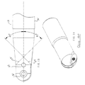
- Fig. 14 shows a prior art design.
- Fig. 1 - 6 show a rotary cutting tool assembly 10 including a holder 12 and an insert 14 fixed immovably in the holder 12.
- the insert 14 comprises an elongated body provided on both ends with two full ball end cutting faces 16 having a continuous spiral fluted configuration.
- Each of these cutting faces 16 consists of two radius cutting edges 18 joining at the center with a web 20, thus forming a tip of the respective full ball nose end.
- the cutting edges 18 follow a true helix configuration (see Fig. 3), wherein each cutting face 16 is made of a continuous curve following a spiral configuration without forming any straight faced segment.
- the helix angles of the cutting edges 18 in the insert 14 with respect to a longitudinal axis are between 3° to 45° on both right and left hand directions .
- the helix angle is chosen between 10 and 15° as shown on Fig. 2. Theoretically, it is possible to make the angle wider than 45°, but in this case other considerations such as thickness of the insert come into play.
- the insert 14 is provided with two identical locating set of grooves 22A, 22B and 23A, 23B formed near each ball end cutting face 16.
- the locating set of grooves 22A, 22B, 23 A and 23B are oriented under 45° with respect to the longitudinal axis.
- locating set of grooves 22A and 22B are oriented in the opposite direction with respect to a set of location grooves 23A and 23B.
- the insert 14 has two openings 26 provided for fixing the insert 14 into the holder 12 by means of a specially designed slot 36 formed at one end of the holder 12.
- the slot 36 divides the end of the holder 12 into two symmetrical halves identified as 40 and 42.
- the inner surfaces of halves 40 and 42 have two identical seating faces 24 and 25 better shown on Figs 10 and 11. Each of these seating faces are made under 45° with respect to the longitudinal axis, but are oriented in opposite directions.
- Each of the halves 40 and 42 is provided with a set of openings 28 and 30, wherein the opening 28 has a slightly smaller diameter than opening 30. As it may be seen on Fig. 11, on half 40 the larger opening 30 is closer to the tip than the smaller opening 28, wherein on Fig. 10 it is vice versa.
- insert 14 The fixing of insert 14 into the slot 36 is provided by means of screws 32 and 34. Opening 30 of the half 42 and opening 28 of the half 40 are slightly off center to allow the insert 14 to be pushed against the corresponding seating faces.
- the insert 14 is positioned into the slot 36, then the screw 34 is inserted through the opening 26 of the insert 14 which is placed to correspond with the opening 28 of the half 42 and opening 30 of the half 40. This allows to preliminarily fix the insert inside of the slot 36.
- second screw 32 is inserted into the second opening 26 of the insert 14 which corresponds with the opening 30 of the half 42 and opening 28 of the half 40.
- the holder 12 is made from solid steel and the insert 14 is made from highspeed steel or carbide.
- the fluted configuration of the insert 14 is made by means of a grinding wheel.
Landscapes
- Engineering & Computer Science (AREA)
- Mechanical Engineering (AREA)
- Milling Processes (AREA)
Priority Applications (1)
| Application Number | Priority Date | Filing Date | Title |
|---|---|---|---|
| EP99300173A EP1020246A1 (de) | 1999-01-12 | 1999-01-12 | Schneidwerkzeug |
Applications Claiming Priority (1)
| Application Number | Priority Date | Filing Date | Title |
|---|---|---|---|
| EP99300173A EP1020246A1 (de) | 1999-01-12 | 1999-01-12 | Schneidwerkzeug |
Publications (1)
| Publication Number | Publication Date |
|---|---|
| EP1020246A1 true EP1020246A1 (de) | 2000-07-19 |
Family
ID=8241180
Family Applications (1)
| Application Number | Title | Priority Date | Filing Date |
|---|---|---|---|
| EP99300173A Withdrawn EP1020246A1 (de) | 1999-01-12 | 1999-01-12 | Schneidwerkzeug |
Country Status (1)
| Country | Link |
|---|---|
| EP (1) | EP1020246A1 (de) |
Citations (3)
| Publication number | Priority date | Publication date | Assignee | Title |
|---|---|---|---|---|
| EP0096147A1 (de) * | 1982-06-10 | 1983-12-21 | Seco Tools Ab | Schneidwerkzeug und dazugehörige Schneidplatte |
| DE3529620A1 (de) * | 1985-08-19 | 1987-02-19 | Kieninger Walter Gmbh | Schneidplatte |
| EP0642864A1 (de) * | 1993-09-13 | 1995-03-15 | Iscar Limited | Schneidwerkzeug |
-
1999
- 1999-01-12 EP EP99300173A patent/EP1020246A1/de not_active Withdrawn
Patent Citations (3)
| Publication number | Priority date | Publication date | Assignee | Title |
|---|---|---|---|---|
| EP0096147A1 (de) * | 1982-06-10 | 1983-12-21 | Seco Tools Ab | Schneidwerkzeug und dazugehörige Schneidplatte |
| DE3529620A1 (de) * | 1985-08-19 | 1987-02-19 | Kieninger Walter Gmbh | Schneidplatte |
| EP0642864A1 (de) * | 1993-09-13 | 1995-03-15 | Iscar Limited | Schneidwerkzeug |
Similar Documents
| Publication | Publication Date | Title |
|---|---|---|
| US5915888A (en) | Rotary cutting tool assembly | |
| KR100776555B1 (ko) | 드릴링 공구 및 인덱서블 드릴 비트 | |
| US7997836B2 (en) | Indexable type cutting tool | |
| US8066454B2 (en) | Milling tool with cooperating projections and recesses between the cutting insert and the holder | |
| US7001114B2 (en) | Device for chip removing machining | |
| US5947653A (en) | Helix drill having coolant channels and helical chip flutes | |
| RU2547365C2 (ru) | Регулируемое сверло с механическим креплением многогранных режущих пластин | |
| EP0841115A1 (de) | Bohrer mit Schneideinsätzen | |
| JP2004527391A (ja) | 交換式カッターヘッドを切削工具の自由端に有する回転工具 | |
| US7309193B2 (en) | Indexable insert with corners with different radii | |
| MX2011002730A (es) | Broca ajustable e indexable y sistema modular y portador. | |
| KR101081786B1 (ko) | 회전 절삭 기계 가공용 밀링 커터 | |
| CZ20012280A3 (cs) | Nástroj a řezná hlava pro třískové obrábění | |
| US20100034607A1 (en) | Adjustable indexable drill and modular system and holder | |
| US5993119A (en) | Drill having cooling channel and chip flutes | |
| US7641423B2 (en) | Apparatus for chip removing machining | |
| US7390151B2 (en) | Helical cutter head and helical cutting blade for use therewith | |
| CN101198448B (zh) | 带有多个切割刀刃的螺旋切割刀片 | |
| EP1020246A1 (de) | Schneidwerkzeug | |
| KR101276401B1 (ko) | 엔드 밀링 커터 | |
| CN100415421C (zh) | 刀片镶刃 | |
| JP4952068B2 (ja) | スローアウェイ式回転工具 | |
| WO2006036041A1 (en) | Indexable type cutting tool | |
| WO2014150002A1 (en) | Adjustable indexable drill | |
| AU2015258310A1 (en) | Adjustable indexable drill and modular system and holder |
Legal Events
| Date | Code | Title | Description |
|---|---|---|---|
| PUAI | Public reference made under article 153(3) epc to a published international application that has entered the european phase |
Free format text: ORIGINAL CODE: 0009012 |
|
| 17P | Request for examination filed |
Effective date: 19991209 |
|
| AK | Designated contracting states |
Kind code of ref document: A1 Designated state(s): DE ES FR GB IT |
|
| AX | Request for extension of the european patent |
Free format text: AL;LT;LV;MK;RO;SI |
|
| AKX | Designation fees paid |
Free format text: DE ES FR GB IT |
|
| 17Q | First examination report despatched |
Effective date: 20010724 |
|
| STAA | Information on the status of an ep patent application or granted ep patent |
Free format text: STATUS: THE APPLICATION IS DEEMED TO BE WITHDRAWN |
|
| 18D | Application deemed to be withdrawn |
Effective date: 20030130 |