EP1020251A1 - Vis d'assemblage automatique - Google Patents
Vis d'assemblage automatique Download PDFInfo
- Publication number
- EP1020251A1 EP1020251A1 EP98929871A EP98929871A EP1020251A1 EP 1020251 A1 EP1020251 A1 EP 1020251A1 EP 98929871 A EP98929871 A EP 98929871A EP 98929871 A EP98929871 A EP 98929871A EP 1020251 A1 EP1020251 A1 EP 1020251A1
- Authority
- EP
- European Patent Office
- Prior art keywords
- casing
- rotator
- biasing
- clamped
- fitment
- Prior art date
- Legal status (The legal status is an assumption and is not a legal conclusion. Google has not performed a legal analysis and makes no representation as to the accuracy of the status listed.)
- Granted
Links
Images


Classifications
-
- F—MECHANICAL ENGINEERING; LIGHTING; HEATING; WEAPONS; BLASTING
- F16—ENGINEERING ELEMENTS AND UNITS; GENERAL MEASURES FOR PRODUCING AND MAINTAINING EFFECTIVE FUNCTIONING OF MACHINES OR INSTALLATIONS; THERMAL INSULATION IN GENERAL
- F16B—DEVICES FOR FASTENING OR SECURING CONSTRUCTIONAL ELEMENTS OR MACHINE PARTS TOGETHER, e.g. NAILS, BOLTS, CIRCLIPS, CLAMPS, CLIPS OR WEDGES; JOINTS OR JOINTING
- F16B31/00—Screwed connections specially modified in view of tensile load; Break-bolts
- F16B31/04—Screwed connections specially modified in view of tensile load; Break-bolts for maintaining a tensile load
-
- B—PERFORMING OPERATIONS; TRANSPORTING
- B23—MACHINE TOOLS; METAL-WORKING NOT OTHERWISE PROVIDED FOR
- B23P—METAL-WORKING NOT OTHERWISE PROVIDED FOR; COMBINED OPERATIONS; UNIVERSAL MACHINE TOOLS
- B23P19/00—Machines for simply fitting together or separating metal parts or objects, or metal and non-metal parts, whether or not involving some deformation; Tools or devices therefor so far as not provided for in other classes
- B23P19/04—Machines for simply fitting together or separating metal parts or objects, or metal and non-metal parts, whether or not involving some deformation; Tools or devices therefor so far as not provided for in other classes for assembling or disassembling parts
- B23P19/06—Screw or nut setting or loosening machines
-
- B—PERFORMING OPERATIONS; TRANSPORTING
- B25—HAND TOOLS; PORTABLE POWER-DRIVEN TOOLS; MANIPULATORS
- B25B—TOOLS OR BENCH DEVICES NOT OTHERWISE PROVIDED FOR, FOR FASTENING, CONNECTING, DISENGAGING OR HOLDING
- B25B13/00—Spanners; Wrenches
-
- B—PERFORMING OPERATIONS; TRANSPORTING
- B25—HAND TOOLS; PORTABLE POWER-DRIVEN TOOLS; MANIPULATORS
- B25B—TOOLS OR BENCH DEVICES NOT OTHERWISE PROVIDED FOR, FOR FASTENING, CONNECTING, DISENGAGING OR HOLDING
- B25B13/00—Spanners; Wrenches
- B25B13/02—Spanners; Wrenches with rigid jaws
- B25B13/06—Spanners; Wrenches with rigid jaws of socket type
-
- B—PERFORMING OPERATIONS; TRANSPORTING
- B25—HAND TOOLS; PORTABLE POWER-DRIVEN TOOLS; MANIPULATORS
- B25B—TOOLS OR BENCH DEVICES NOT OTHERWISE PROVIDED FOR, FOR FASTENING, CONNECTING, DISENGAGING OR HOLDING
- B25B21/00—Portable power-driven screw or nut setting or loosening tools; Attachments for drilling apparatus serving the same purpose
Definitions
- the present invention relates to an automatic screw clamping device of automatically clamping clamped members such as bolt, nut and the like which are attached to the mount element.
- the clamped members such as bolt, nut, etc.
- the clamped members have been so far widely used for fastening together various kinds of building articles or railroad ties and rails.
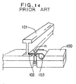
- a press spring 103 having a plate-like portion 102 laid over between a tie 100 and a rail 101 is pressed down by clamping a bolt n to the tie 100 to fix the rail 101 on the tie 100.
- the bolt n may loosen automatically even though the bolt n undergoes the biasing force of the press spring 103.
- this specific device comprises a cylindrical rotator a, a tubular casing b of receiving the rotator a in a manner that the latter is rotatable and slidable axially and vertically, and a coiled spring c wound around the rotator a to give the turning effort to the rotator a, wherein the rotator a has an engaging portion a1 on the inner periphery thereof for receiving a nut n which is threadedly engaged with a strap bolt, and a projection a2 extending in an outward direction of the diameter on the outer periphery of the upper end, while there is provided on the lower end of the casing b a drive-fit/fixing means b1 such as nail, and on the inner periphery a depression b2 of receiving said projection a2 in a manner that the latter is kept unrotatable.
- the rotator a has an engaging portion a1 on the inner periphery thereof for receiving a nut n which is
- the casing b can be fixed by driving into the wood the drive-fit/fixing means b1 such as nail provided on the upper end of the casing b, if the metallic press spring 103 affixed in the railroad rail 101 as shown in fig.14 is kept pressed down by the bolt n, the casing b can not be fixed to the tie by the driven fixing means b1 such as nail because the metallic press spring 103 is disposed around the bolt n. Consequently, it would be difficult to adapt the automatic clamping device for building strap bolt as illustrated by fig.15 to bolt or nut fitted in the metallic mount element 101, 103.
- a first object of which is to provide an automatic screw clamping device which is capable of preventing a bolt fitted in the metallic mount element that is hard to nail from loosening by retightening the bolt.
- a second object of this invention is to provide an automatic screw clamping device which can be readily and for a short time fitted to the metallic mount element that is hard to nail.
- a third object of the present invention is to provide an automatic screw clamping device for fixing bolt for railroad rail, which may be easily fitted to the fixing bolt for railroad rail secured to the railroad rail to prevent the fixing bolt for railroad rail from loosening by automatically retightening the said bolt.
- a fourth object of the present invention is to provide an automatic screw clamping device which, while in use with nut or bolt, may be easily identified and detected at once even if it has been removed from the nut or bolt by other person with the intention of loosening the latter.
- the present invention can solve the above-described tasks by providing automatic screw clamping devices containing the following characteristic features.
- a first invention of the present application is provided with a biasing member 5, 110 for biasing clamped member n such as bolt, nut and the like in a direction in which the latter runs for being tightened.
- the clamped member n Owing to the arrangement that the biasing member 5, 110 is in an unrotatable engagement with the clamped member n at one end thereof, the clamped member n is adapted to be biased in a direction in which it runs for being tightened.
- fitting means 71, 112, 82, 802 of fitting the other end of biasing members 5, 110 on a mount element 8, 800 with the clamped member n attached thereto.
- the fitting means 71, 112, 82, 802 is intended to allow the other end of the biasing member 5, 110 to move by the biasing force applied to the other end of the biasing member 5, 110, thereby, upon such a movement, putting the other end of the biasing member 5, 110 and the mount element 8, 800 together.
- the fitting means in accordance with the first invention comprises fitment 71, 112 provided at one of the other end of the biasing member 5, 110 and the mount element 8, 800, and fitment-receptive portion 82, 802 at the other.
- the fitment 71, 112 is relatively movable toward the fitment-receptive member 82, 802 by the biasing force applied to the fitment 71, 112, whereby upon such a movement, the fitment 71, 112 is received by the fitment-receptive member 82, 802.
- the mount element in accordance with the first or second invention comprises a clamping object of clamping the clamped member, and a washer member 8, 800.
- Said washer member 8, 800 is disposed between the clamping object and the clamped member n so as to get in contact with the other end of the biasing member 5, 110.
- a fourth invention of the present application comprises a tubular casing 2, a rotator 4 disposed within said casing 2 in a manner that the former may move axially and vertically, and biasing member 5.
- the biasing member 5 is connected with the rotator 4 at one end thereof, and the casing 2 at the other end, whereby the casing 2 and rotator 4 are given by the biasing force of the biasing member 5 a turning effort by which both the members can rotate relative to each other.
- the rotator 4 is provided with an engaging portion 41 at the lower end thereof, whereby it can unrotatably engage the clamped member n such as bolt, nut and the like.
- the casing 2 and rotator 4 include locking means 32, 42 which are removably lockable, respectively. Therefore, the rotator 4 can be maintained within the casing 2 in a biased position where it holds a given turning effort, and the interlock between the casing 2 and rotator 4 can be removed as the rotator 4 is actuated to move upward relative to the casing 2.
- a fitting means 71, 82 of connecting the casing 2 and the mount element 8 with clamped member n attached thereto in an unrotatable manner The fitting member 71, 82 acts to turn the casing 2 under the influence of the biasing force of the biasing member 5 applied to the casing 2, and upon such rotary motion, the casing 2 and the mount element 8 are unrotatably joined together, and the rotator 4 as engaged with the clamped member n is operative to bias the clamped member n in a direction in which the latter runs for being tightened.
- the attachement of the other end of the biasing member 5, 110 to the mount element 8, 800 is effected by a biasing force applied to the other end of the biasing member 5, 110 and counter to a direction in which the clamped member n runs for being tightened.
- the mounting operation may be simplified such that the other end of the biasing member 5, 110 can be spontaneously attached to the fitting member 8, 800 by the use of the elasticity of the coil spring 1 without the necessity of driving nails as in the past.
- the mounting operation can be simply achieved, too; in order to remove the locked joint between the casing 2 and the rotator 4, all what can be done is to engage the clamped member n with the rotator 4. This may help put the casing 2 in rotary motion under the influence of the biasing force of the biasing member 5 applied to the casing 2, and upon such rotary motion, the casing 2 may be unrotatably attached to the fitting member 8 in a natural manner.
- Fig.1 is an exploded perspective view of an automatic screw clamping device in accordance with a first embodiment of the present invention.
- the automatic screw clamping device of the first embodiment comprises a cylindrical casing 2, a rotator 4 rotatably disposed within the casing 2, a biassing member 5, and a covering member 6.
- the casing 2 comprises a tubular casing body 3 and a disc-like bottom plate 7 mounted on the casing body 3.
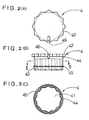
- the casing body 3 has on the upper end thereof an upper projecting portion 31 protruding in an inward direction of the diameter, as seen in figs.3 (A)(B)(C).
- the inner periphery of this upper projecting portion 31 provides a locking hole 32 with substantially twenty-four straight sides for stopping rotation.
- This specific spring locking/receiving portion 33 is intended to lock and receive a coil spring 5 as biassing member 5, which will be detailed afterward, at its lower end, including a spring-receptive portion 33a formed by a part of the inner periphery of the casing body 3 so as to extend in an outward direction of the diameter, and a spring catching piece 33b extending from one end of the spring-receptive portion 33a toward a peripheral direction of the casing body 3.
- the bottom plate 7 matches with the casing body 3 in the shape of the outer periphery.
- the bottom plate 7 has four fitments 71 ⁇ 71 formed on the outer periphery thereof to project in an outward direction of the diameter.
- the bottom plate 7 is fixedly secured to the lower end of the casing body 3.
- the bottom plate 7 is placed on the lower face of the casing body 3 so that the fixing pieces 34 ⁇ 34 are fitted into fit-in holes 72 ⁇ 72 provided on the outer periphery of the bottom plate 7, and the fixing pieces 34 ⁇ 34 projecting from the fit-in holes 72 ⁇ 72 downwardly of the bottom plate 7 are bent toward the inside of the diameter so that the fixing pieces 34 ⁇ 34 may be securely fixed to the casing body 3.
- the bottom plate 7 which has been fixed to the casing body 3 in this way provides a lower face of the casing 2 and a through hole 73 formed in the inner periphery thereof for receiving the rotator 4.
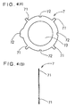
- the rotator 4 has an engaging hole 41 formed on the lower side to extend from the lower face to the upper side.
- This engaging hole 41 is intended to retain clamped members such as nut or bolt against turning.
- hexagon will do in order to correspond to hexagonal nut or bolt.
- said engaging hole 41 is provided with multiple straight sides suitable for easier engagement with hexagonal bolt or nut.
- the rotator 4 has locking portion 42 having twenty-four straight sides formed on the upper periphery thereof for lockably fitting in the locking hole 32 of the casing body 2.
- a spring fit-on portion 44 In the lower side of the outer periphery of the rotator 4, there are provided a spring fit-on portion 44, an inserting portion 43 formed in the lower side of the spring fit-on portion 44, and a stop portion formed between the spring fit-on portion 44 and the inserting portion 43.
- the spring fit-on portion 44 is intended for fitting spring 5 thereon, and has a diameter smaller than the locking portion 42.
- the inserting portion 43 is substantially equal to that of the through hole 73 of the bottom plate 7 in the casing 2, and adapted to enter into and go downwardly of the casing 2 until it fits into the through hole 73.
- the stop portion 45 is made in diameter smaller than locking hole 32 of the casing 2, and larger than the through hole 73.
- the stop portion 45 may be stopped by abutting on the peripheral portion of the through hole 73 of the bottom plate 7 with the inserting portion 43 of the rotator 4 fit in the casing being received by the through hole 73 of the casing 2. With the stop portion 45 remaining in position in the peripheral portion of the through hole 73 of the bottom plate 7, the locking portion 42 of the rotator 4 may be brought into a locked position in the locking hole 32 of the casing 2, as shown in fig.7(B).
- Fig.8(B) shows that at the time when the inserting portion 43 jutting downwardly of the casing 2 is pushed upward to get into the casing 2 and move in an upward direction until the lower end of the rotator 4 substantially meets the lower face of the bottom plate 7 of the casing 2, the locking portion 42 of the rotator 4 comes off from the locking hole 32 of the casing 2 and upward in such a manner that both the members will be detached one from another, and the rotator 4 will become rotatable relative to the casing 2.
- a locking groove 46 for locking the upper end of the coil spring 5 is formed at the rotator's side to extend from the locking portion 42 to the spring fit-on portion 44 in the rotator 4, having a predetermined depth ranging from the outer periphery inward of the diameter.
- the biasing member 5 is constituted by elastic coil spring 5 which is produced by winding a copper wire, as shown in fig.1.
- the coiled spring 5 has an upper lock-fit portion 51 formed in the upper end thereof. Said upper lock-fit portion 51 is intended to be locked to the locking groove 46 of the rotator 4.
- the upper lock-fit portion 51 is bent in an inner direction of the diameter and made waveform, each wave having an amplitude larger than the width of the locking groove 46 of the rotator 4.
- the lower lock-fit portion 52 is intended to be locked by the spring-receptive portion 33 of the casing 2, and it is bent in an outward direction of the diameter into a form of the alphabetical U.
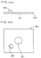
- the covering member 6 is made of transparent synthetic resin. As shown in figs.5(A)(B), its inner peripheral shape is substantially identical to the outer peripheral shape of the casing 2, and there are provided in the lower end fitment-receptive holes 61 ⁇ 61 for receiving fitments 71 ⁇ 71 so that the each fitment having a length extending from the upper end to the lower end of the casing 2 may be thrust home into the hole 61. There is provided a slip-preventive projection 62 in the inner periphery of the lower end of the covering member 6. The slip-preventive projection 62 is intended to prevent the covering member 6 spreading over the casing 2 from slipping out of the casing 2.
- a light reflecting member 63 at the rear side of the upper face of the covering member 6 in order to reflect light beams coming through the upper face of the covering member 6.
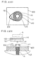
- a washer member 8 is placed on the lower side of the head n1 of the rail fixing bolt n.
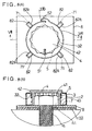
- the washer member 8 used in this embodiment is made of a square plate as shown in fig.6, having in the center thereof a threaded portion fit-in hole 81 for receiving the thread portion of bolt n.
- Each of said fitment-receptive portions may receive each of the fitments 71 ⁇ 71 of the casing in its inside by means of a portion of the washer body 81 cut and raised in square form in the position corresponding to the fiment 71.
- An opening 82a is formed between one side of the fitment-receptive portion 82 facing the thread portion fit-in hole 81 and the other side adjacent to the one side.
- the washer member 8 may be made equal to press spring 103 in breadth, having extensions 83, 83 (shown by dotted lines) formed to extend from both sides of the washer member 8 downward. Such extensions 83, 83 allow the press spring 103 to be positioned therebetween so that the washer member 8 will be prevented from turning relative to the press spring 103.
- the rail fixing bolt n is held down in a railroad tie 100 with the washer member 8 interposed between the press spring 103 and the head n1 of the rail fixing bolt n.
- the mount member on which rail fixing bolt n as a clamped member is mounted is constituted by the railrod tie 100 as an object in which the rail fixing bolt n is tightened and the press spring 103.
- the locking hole 41 of the rotator 4 in a biased position where the rotator 4 is locked to the casing 2 is fitted onto the head n1 of the rail fixing bolt n so as to abut the lower face of the rotator 4 against the upper face of the washer member 8. Then, the casing 2 is struck with hand or hammer in the surface thereof to go downward. In this case, the casing 2 only descents because the rotator 4 remains inactive.
- the bottom plate 7 of the casing 2 comes in contact with the upper face of the washer member 8, almost concurrently followed by detachment of the locking portion 42 of the rotator 4 from the locking hole 32 of the casing 2.
- This detachment may cause one of the casing 2 and rotator 4 to turn relative to the other, with the result that the casing 2 will change over from the state as shown by fig.8(A) to the counterclockwise rotation.
- This rotary motion of the casing 2 may invite the fitments 71 ⁇ 71 of the casing 2 to automatically enter into the interior of the fitment-receptive portions 82, 82 of the washer member 8 through the openings 82a ⁇ 82a until the casing 2 stops turning, as shown in fig.8(B).
- This may enable connection of the casing 2 with the washer member 8, and the fitments 71 ⁇ 71 encased in the fitment-receptive portions 82, 82 are biassed by the coil spring 5, whereby the fitements can be prevented from coming off from the openings 81a ⁇ 81a to ensure that the casing 2 will be securely fixed to the washer member 8.
- the rotator 4 will rotate clockwise under the influence of the coil spring 5. This may help turn the rail fixing bolt n clockwise into a tightened position.
- the washer member 8 is also pressed by the head n1 of the rail fixing bolt n into a firmly fixed position. After being tightened, the rail fixing bolt n can be kept biassed to run in a direction in which it is further tightened.
- the rail fixing bolt n can be automatically tightened by means of the elasticity of the coil spring 5, thus resulting in maintenance of the tightening torque at a constant level at all times.
- the covering member 6 is put on the casing 2, and as shown in figs.9(A)(B), the fitment-receptive portions 82, 82 of the washer member 8 enter into the fitment-receptive holes 61 ⁇ 61 of the covering member 6, and simultaneously, the slip-preventive projection 62 of the covering member 6 may force itself into the space between the lower face of the bottom plate 7 of the casing 2 and the upper face of the washer member 8. Consequently, the covering member 6 can neither rotate nor move in a vertical direction under this condition, thereby being completely fixed by the washer member 8. The mounting operation comes to end at this stage.
- the described structure makes it possible to securely fix the body portion 1 to the press spring 103 which is hard to nail.
- the casing 2 may be removed from the rotator 4 while the casing 2 is kept engaged with the rail fixing bolt n. This permits fixing of the casing 2 to the washer member 8 under the influence of the elasticity of the coil spring 5. Therefore, the mounting operation can take place easily.
- the rail fixing bolt n can not be manipulated without removing the covering member 6 from the casing 2 capped with said covering member 6, which may prevent other persons from loosening and removing the rail fixing bolt n.
- the covering member 6 since the covering member 6 is provided with the light reflecting member 63, the covering member 6 can be easily located at the sight of a light reflected from the member 63.
- the locations of the covering members 6 can be found by a light attached to the existing railroad vehicle, or by a light for exclusive use in identifying the light reflecting member provided on the existing railroad vehicle, as said vehicle runs. If other person has removed the covering member 6 to loosen the rail fixing bolt n, it can be found out instantly.
- the covering member 6 acts to prevent invasion of those substances into the casing 2, which may avoid any functional damage of the coil spring, and thus the rail fixing bolt n can be held in a tightened position.
- the fitments 71 ⁇ 71 of the casing 2 may be fixed to the object acting as the mount member on which the rail fixing bolt n is mounted and combined with the washer member 8, e.g. an object provided with the fitment-receptive portions 82, 82 placed on the washer member 8.
- the fitments 71 ⁇ 71 of the casing 2 may be fixed to the object acting as the mount member on which the rail fixing bolt n is mounted and combined with the washer member 8, e.g. an object provided with the fitment-receptive portions 82, 82 placed on the washer member 8.
- Proper variations are permissible.
- covering member 6 this member may not necessarily be used. Proper variations are permissible.
- the first embodiment employs the light reflecting member 63, but may not always use this member. If used, the light reflecting member 63 is not especially limited in its position. For example, it may be disposed on the upper side of the top face of the covering member 63, or the inside or outside of the side face of the covering member 63, or a part of the casing 2. Proper variations are permissible.
- the first embodiment uses a coil spring as biasing means, but for example, a coiled steel leaf spring may be used. Proper variations are permissible.
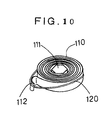
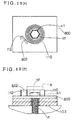
- the automatic screw clamping device of the second embodiment comprises a coiled spring 110 as a biasing means, and a retainer member 120 for retaining the coiled spring 110 in a winding-elastic condition.
- This device does not have a casing 2 as used in the first embodiment.
- the engagement hole 111 may be formed by bending the inner peripheral side of the coiled spring 110 into a hexagonal form. This engagement means may not necessarily have such a structure.
- the rotator 4 with an engaging hole 41 (as in the previous embodiment) is attached to the inner peripheral end of the coiled spring 110, or an engaging piece is positioned in a manner that it may engage a groove formed in the clamped member, or the clamped member is mounted in the inner peripheral end of thereof in advance.
- a catching piece 112 is provided on the outer peripheral end of the coiled spring 110 a catching piece 112 as an attachment for catching on a washer member 800 as explained afterward.
- This catching piece 112 is formed by bending the outer peripheral end of the coiled spring 110 into an alphabetical U.
- the retaining member 120 which is made of a string-formed member, is so wound around the entire outer periphery of the coiled spring 110 with winding elasticity that it may serve to prevent the coiled spring 110 from spreading because of the winding elasticity, whereby the coiled spring 110 is retained in a winding-elastic condition.
- the washer member 800 for use with the automatic screw clamping device in accordance with the second embodiment is shown in fig.11.
- the washer member 800 is constituted by a square member and includes in its central portion a threaded shank fit-in hole 801 for receiving the threaded shank of a bolt n.
- the threaded shank fit-in hole 801 has on its left-hand side a projecting fitment-receptive portion 802 which is formed by cutting and raising a part of the washer member 800.
- the automatic screw clamping device of the second embodiment may be used in the rail fixing bolt n as described in the first embodiment in the following manner.
- the coiled spring 110 is positioned above the rail fixing bolt n so as to align the engaging hole 111 of the coiled spring 110 with the rail fixing bolt n, and the catching piece 112 of the coiled spring 110 with the fitment-receptive portion 802 of the washer member 800, and the coiled spring 110 is pressed down. It may be done by hand, but if the coiled spring 110 is struck on the upper face using a plate-like tooling K as shown by a dotted line in fig.12(B), the whole coiled spring 110 can be pushed down at a stretch. This latter method is preferable in that the pressing can be simply achieved.
- the catching piece 112 of the coiled spring 110 can catch the fitment-receptive portion 802 of the washer member 800 by virtue of the winding elasticity of the coiled spring 110, and on the other hand, the rail fixing bolt n received by the engagement hole 111 can remain biased in a direction in which it runs for being tightened.
- this embodiment will do without casing or rotator 4 as in the body portion 1 of the first embodiment. Therefore, the structure may be made simple, the production cost is low, and a good economy can be achieved.
- the washer member 800 may be provided with a locking means for locking the covering member to the washer member 800, so that the covering member placed over the coiled spring 110 set in position may be locked to the washer member 800.
- This arrangement may prevent iron powder or dust from settling on the coiled spring, thus resulting in avoidance of functional damage of the coiled spring to such an extent that the rail fixing bolt n will be kept biassed toward a direction in which it runs for being tightened.
- Provision of a light reflecting member on the covering member as used in the first embodiment is preferable in that the location of the covering member can be easily identified.
- the fitment-receptive portion 802 of the washer member 800 as used in the second embodiment is constituted by a projection formed by a cut and raised part of the washer member 800, any other thing that may be caught by the catching piece 112 of the coiled spring 110 will do. Proper variations are permissible.
- the retaining member 120 is arranged such that it should be automatically removed from the coiled spring 110.
- the engaging hole 111 of the coiled spring 110 may be fit on the rail fixing bolt n ,and the locking piece provided on the outer peripheral end of the coiled spring 110 is fit in the locking groove formed on the washer member respectively before removing the retaining member 120 as by cutting it.
- Proper variations are permissible.
- this second embodiment does not use an exclusive washer member 800 but a press spring 103 having means which can be caught by the catching piece 112 of the coiled spring 110. Proper variations are permissible. The above is the description of the second embodiment.
- the automatic screw clamping device in accordance with the present invention may be applied not only to the rail fixing bolt n firmly secured to the railroad rail 101 as described above but also to various types of bolts and nuts. Bolts for exclusive use in pylons can be prevented from loosening if they are used together with said washer members 8, 800. The locations of the automatic screw clamping devices attached to the said bolts could be identified by shining a beam of light at the pylons, and any bolt loosened by other persons could be detected instantly on the ground.
- the pylons to which bolts are to be applied provide an object with bolt attachment, and a combination of the pylons and washer members 8, 800 constitutes a mount member with bolts attached thereto.
- the mount member with bolt and nut attached thereto is made of a substance which is hard to nail, such as metal or concrete, the automatic screw clamping device of the present invention may be easily and unrotatably fitted to the mount member. Said device is especially adaptable to bolts or nuts being fitted to the mount members which are hard to nail, and also available for bolts or nuts being attached to wood. Proper variations are permissible.
- the biasing member (5, 110) can be also fixed by the other ends thereof to a member which are hard to nail, while biasing clamped members n in a direction in which it runs for being tightened. Additionally, unlike the conventional practice, the mounting operation is simple in that the biasing member (5, 110) may be automatically fitted by the other end thereof to the mount member(8, 800) under the influence of the elastic force of the coil spring 1 without using nails.
- the mounting operation is simple in that the casing 2 may be detached from the rotator 4 by engaging the rotator 4 with the clamped member n, so that the casing 2 may be turned by the biasing force from the biasing member 5. Upon turning, the casing 2 and the mount member 8 may be automatically and unrotatably joined together.
Landscapes
- Engineering & Computer Science (AREA)
- Mechanical Engineering (AREA)
- General Engineering & Computer Science (AREA)
- Clamps And Clips (AREA)
- Connection Of Plates (AREA)
- Details Of Spanners, Wrenches, And Screw Drivers And Accessories (AREA)
Applications Claiming Priority (1)
| Application Number | Priority Date | Filing Date | Title |
|---|---|---|---|
| PCT/JP1998/003070 WO2000001509A1 (fr) | 1998-07-06 | 1998-07-06 | Vis d'assemblage automatique |
Publications (3)
| Publication Number | Publication Date |
|---|---|
| EP1020251A1 true EP1020251A1 (fr) | 2000-07-19 |
| EP1020251A4 EP1020251A4 (fr) | 2004-05-26 |
| EP1020251B1 EP1020251B1 (fr) | 2006-08-30 |
Family
ID=14208575
Family Applications (1)
| Application Number | Title | Priority Date | Filing Date |
|---|---|---|---|
| EP98929871A Expired - Lifetime EP1020251B1 (fr) | 1998-07-06 | 1998-07-06 | Vis d'assemblage automatique |
Country Status (8)
| Country | Link |
|---|---|
| US (1) | US6257813B1 (fr) |
| EP (1) | EP1020251B1 (fr) |
| JP (1) | JP3730866B2 (fr) |
| KR (1) | KR20010023727A (fr) |
| CN (1) | CN1128691C (fr) |
| CA (1) | CA2302613A1 (fr) |
| DE (1) | DE69835759T2 (fr) |
| WO (1) | WO2000001509A1 (fr) |
Cited By (2)
| Publication number | Priority date | Publication date | Assignee | Title |
|---|---|---|---|---|
| EP1310685A4 (fr) * | 2000-08-16 | 2005-01-12 | Kashiraishi Inc | Dispositif de serrage |
| CN116748840A (zh) * | 2023-06-20 | 2023-09-15 | 一汽解放汽车有限公司 | 点火线圈护套的拆卸装置 |
Families Citing this family (17)
| Publication number | Priority date | Publication date | Assignee | Title |
|---|---|---|---|---|
| US6494654B2 (en) * | 1996-11-04 | 2002-12-17 | Thomas M. Espinosa | Tie down building, system tie down, and method |
| EP1511942B1 (fr) | 2002-06-10 | 2008-02-20 | Acument Intellectual Properties, LLC. | Ecrou de contact en une piece |
| EP1568902B1 (fr) * | 2002-12-02 | 2007-03-14 | Kashiraishi Inc. | Systeme de fixation |
| US7682100B2 (en) * | 2004-10-22 | 2010-03-23 | Nectar, Inc. | Self-tightening fastening system |
| US7168343B2 (en) * | 2005-03-09 | 2007-01-30 | Simpson Strong-Tie Company, Inc. | Limited access building connection |
| US7708509B1 (en) * | 2009-05-08 | 2010-05-04 | Bennett Bruce A | Locking retainer for threaded fasteners |
| CN102107323B (zh) * | 2010-12-29 | 2011-12-21 | 天津商科数控设备有限公司 | 电阻焊熔核质量控制方法 |
| US20130136557A1 (en) * | 2011-11-30 | 2013-05-30 | Yuan Yu Wang | Bolt assembly |
| US8881478B2 (en) | 2012-06-22 | 2014-11-11 | Simpson Strong-Tie Company, Inc. | Ratcheting take-up device |
| US9394706B2 (en) | 2013-10-08 | 2016-07-19 | Simpson Strong-Tie Company, Inc. | Concrete anchor |
| US9163655B2 (en) | 2014-01-14 | 2015-10-20 | Kaoru Taneichi | Thrust nut |
| CN105033899B (zh) * | 2015-07-23 | 2016-11-30 | 浙江斯菱汽车轴承股份有限公司 | 一种汽车轮毂轴承全自动保持架装球机 |
| EP3276167B8 (fr) * | 2016-07-27 | 2019-06-19 | Siemens Gamesa Renewable Energy A/S | Raccord à boulon destiné à une tour d'une éolienne |
| JP7292127B2 (ja) * | 2019-06-25 | 2023-06-16 | 株式会社青山製作所 | 締結具 |
| CN110181263B (zh) * | 2019-07-02 | 2024-01-02 | 重庆市灵龙自动化设备有限公司 | 具有定位功能的螺丝机传送装置 |
| US20230254974A1 (en) * | 2022-02-09 | 2023-08-10 | Zt Group Int'l, Inc. Dba Zt Systems | Printed circuit board thumbscrew locking reinforcement structure |
| EP4354230B1 (fr) * | 2022-10-12 | 2026-04-22 | Omega SA | Presse pour le chassage d'une lunette ou d'une glace de montre |
Family Cites Families (18)
| Publication number | Priority date | Publication date | Assignee | Title |
|---|---|---|---|---|
| DE490519C (de) * | 1930-01-29 | Stefan Mikuda | Schraubenmuttersicherung | |
| US292301A (en) * | 1884-01-22 | John w | ||
| US582424A (en) * | 1897-05-11 | Nut-lock | ||
| US1483317A (en) * | 1922-06-30 | 1924-02-12 | John H Brookman | Connecting-rod bolt |
| US1631878A (en) * | 1924-04-26 | 1927-06-07 | Miller Otto | Automatic take-up bolt |
| US1627401A (en) * | 1925-10-19 | 1927-05-03 | Gustav C Monckmeier | Wear-compensating bolt |
| US1829940A (en) * | 1926-09-13 | 1931-11-03 | Gustav C Monckmeier | Wear compensating bolt |
| US1749341A (en) * | 1927-02-07 | 1930-03-04 | Dick H Groenewold | Adjusting bolt |
| JPS5080668U (fr) * | 1973-12-03 | 1975-07-11 | ||
| JPS6035912U (ja) * | 1983-08-19 | 1985-03-12 | 石毛 民雄 | ボルト |
| JPS60157508A (ja) * | 1984-01-26 | 1985-08-17 | 高橋 宏通 | バネ付きナット |
| JPH045524Y2 (fr) * | 1986-11-25 | 1992-02-17 | ||
| US4801231A (en) * | 1987-04-10 | 1989-01-31 | Aec-Able Engineering Company, Inc. | Self-driven nut and joinders incorporating it |
| US4812096A (en) * | 1987-12-11 | 1989-03-14 | Peterson Peter O | Self-tightening nut |
| DE4121524C2 (de) * | 1991-06-28 | 1994-07-14 | Deutsche Aerospace Airbus | Schraubenverbindung |
| JP2508453Y2 (ja) * | 1992-06-03 | 1996-08-21 | 株式会社谷村設計 | 建築用羽子板ボルト自動締付装置 |
| JPH0642034U (ja) | 1992-11-25 | 1994-06-03 | 日本電気精器株式会社 | 自動ねじ締め機 |
| JPH08215952A (ja) | 1995-02-15 | 1996-08-27 | Ishikawajima Harima Heavy Ind Co Ltd | ボルト締付装置 |
-
1998
- 1998-07-06 US US09/486,120 patent/US6257813B1/en not_active Expired - Fee Related
- 1998-07-06 EP EP98929871A patent/EP1020251B1/fr not_active Expired - Lifetime
- 1998-07-06 CN CN98808848A patent/CN1128691C/zh not_active Expired - Fee Related
- 1998-07-06 DE DE69835759T patent/DE69835759T2/de not_active Expired - Fee Related
- 1998-07-06 WO PCT/JP1998/003070 patent/WO2000001509A1/fr not_active Ceased
- 1998-07-06 JP JP2000557939A patent/JP3730866B2/ja not_active Expired - Fee Related
- 1998-07-06 CA CA002302613A patent/CA2302613A1/fr not_active Abandoned
- 1998-07-06 KR KR1020007002381A patent/KR20010023727A/ko not_active Withdrawn
Cited By (2)
| Publication number | Priority date | Publication date | Assignee | Title |
|---|---|---|---|---|
| EP1310685A4 (fr) * | 2000-08-16 | 2005-01-12 | Kashiraishi Inc | Dispositif de serrage |
| CN116748840A (zh) * | 2023-06-20 | 2023-09-15 | 一汽解放汽车有限公司 | 点火线圈护套的拆卸装置 |
Also Published As
| Publication number | Publication date |
|---|---|
| CN1269741A (zh) | 2000-10-11 |
| US6257813B1 (en) | 2001-07-10 |
| DE69835759D1 (de) | 2006-10-12 |
| WO2000001509A1 (fr) | 2000-01-13 |
| EP1020251A4 (fr) | 2004-05-26 |
| CN1128691C (zh) | 2003-11-26 |
| EP1020251B1 (fr) | 2006-08-30 |
| DE69835759T2 (de) | 2007-04-12 |
| CA2302613A1 (fr) | 2000-01-13 |
| KR20010023727A (ko) | 2001-03-26 |
| JP3730866B2 (ja) | 2006-01-05 |
Similar Documents
| Publication | Publication Date | Title |
|---|---|---|
| US6257813B1 (en) | Screw clamping device with automatic clamping means | |
| EP0922867B1 (fr) | Rondelle de retenue et dispositif de retenue utilisant cette rondelle | |
| EP0180965B1 (fr) | Dispositif pour la jonction d'articles | |
| US5649436A (en) | Adhesively mounted security system | |
| US4631985A (en) | Device for holding a screw or the like | |
| JPWO2000001509A1 (ja) | ネジ自動締付装置 | |
| US20080095591A1 (en) | Fastener assembly for metal framing | |
| US6007284A (en) | Nut and connector | |
| US7137768B2 (en) | Fastener assembly | |
| JP3327837B2 (ja) | ネジ自動締付装置 | |
| JP3382412B2 (ja) | 覆工板の締結装置 | |
| GB2067328A (en) | Anti-theft arrangement for vehicle identification plate | |
| CA2161202C (fr) | Barriere de securite souple | |
| JP2700307B2 (ja) | 足場の保持金具 | |
| JP3232838B2 (ja) | フォーク取付構造 | |
| JPS6021540Y2 (ja) | ボルト固定装置 | |
| JPH042185Y2 (fr) | ||
| JPH11210734A (ja) | 止め金具構造 | |
| JPS6128890Y2 (fr) | ||
| JPS632642Y2 (fr) | ||
| JPH0338499Y2 (fr) | ||
| JP3609129B2 (ja) | デッキコネクタ | |
| RU1776591C (ru) | Устройство А.М.Мартовского дл креплени груза на транспортном средстве | |
| JPH0642026Y2 (ja) | 縦樋控金具 | |
| AU725328B3 (en) | Fastener fixing device |
Legal Events
| Date | Code | Title | Description |
|---|---|---|---|
| PUAI | Public reference made under article 153(3) epc to a published international application that has entered the european phase |
Free format text: ORIGINAL CODE: 0009012 |
|
| 17P | Request for examination filed |
Effective date: 20000218 |
|
| AK | Designated contracting states |
Kind code of ref document: A1 Designated state(s): DE FR GB |
|
| A4 | Supplementary search report drawn up and despatched |
Effective date: 20040414 |
|
| RIC1 | Information provided on ipc code assigned before grant |
Ipc: 7F 16B 31/04 B Ipc: 7B 23P 19/06 A |
|
| 17Q | First examination report despatched |
Effective date: 20040812 |
|
| GRAP | Despatch of communication of intention to grant a patent |
Free format text: ORIGINAL CODE: EPIDOSNIGR1 |
|
| GRAS | Grant fee paid |
Free format text: ORIGINAL CODE: EPIDOSNIGR3 |
|
| GRAA | (expected) grant |
Free format text: ORIGINAL CODE: 0009210 |
|
| AK | Designated contracting states |
Kind code of ref document: B1 Designated state(s): DE FR GB |
|
| REG | Reference to a national code |
Ref country code: GB Ref legal event code: FG4D |
|
| REF | Corresponds to: |
Ref document number: 69835759 Country of ref document: DE Date of ref document: 20061012 Kind code of ref document: P |
|
| EN | Fr: translation not filed | ||
| PLBE | No opposition filed within time limit |
Free format text: ORIGINAL CODE: 0009261 |
|
| STAA | Information on the status of an ep patent application or granted ep patent |
Free format text: STATUS: NO OPPOSITION FILED WITHIN TIME LIMIT |
|
| 26N | No opposition filed |
Effective date: 20070531 |
|
| GBPC | Gb: european patent ceased through non-payment of renewal fee |
Effective date: 20070706 |
|
| PG25 | Lapsed in a contracting state [announced via postgrant information from national office to epo] |
Ref country code: FR Free format text: LAPSE BECAUSE OF FAILURE TO SUBMIT A TRANSLATION OF THE DESCRIPTION OR TO PAY THE FEE WITHIN THE PRESCRIBED TIME-LIMIT Effective date: 20070511 |
|
| PG25 | Lapsed in a contracting state [announced via postgrant information from national office to epo] |
Ref country code: GB Free format text: LAPSE BECAUSE OF NON-PAYMENT OF DUE FEES Effective date: 20070706 |
|
| PG25 | Lapsed in a contracting state [announced via postgrant information from national office to epo] |
Ref country code: FR Free format text: LAPSE BECAUSE OF FAILURE TO SUBMIT A TRANSLATION OF THE DESCRIPTION OR TO PAY THE FEE WITHIN THE PRESCRIBED TIME-LIMIT Effective date: 20060830 |
|
| PGFP | Annual fee paid to national office [announced via postgrant information from national office to epo] |
Ref country code: DE Payment date: 20080930 Year of fee payment: 11 |
|
| PG25 | Lapsed in a contracting state [announced via postgrant information from national office to epo] |
Ref country code: DE Free format text: LAPSE BECAUSE OF NON-PAYMENT OF DUE FEES Effective date: 20100202 |