EP1020256A2 - Outil de scellement actionné par poudre - Google Patents
Outil de scellement actionné par poudre Download PDFInfo
- Publication number
- EP1020256A2 EP1020256A2 EP99811148A EP99811148A EP1020256A2 EP 1020256 A2 EP1020256 A2 EP 1020256A2 EP 99811148 A EP99811148 A EP 99811148A EP 99811148 A EP99811148 A EP 99811148A EP 1020256 A2 EP1020256 A2 EP 1020256A2
- Authority
- EP
- European Patent Office
- Prior art keywords
- setting tool
- bearing point
- transmission element
- trigger
- lever
- Prior art date
- Legal status (The legal status is an assumption and is not a legal conclusion. Google has not performed a legal analysis and makes no representation as to the accuracy of the status listed.)
- Granted
Links
Images


Classifications
-
- F—MECHANICAL ENGINEERING; LIGHTING; HEATING; WEAPONS; BLASTING
- F16—ENGINEERING ELEMENTS AND UNITS; GENERAL MEASURES FOR PRODUCING AND MAINTAINING EFFECTIVE FUNCTIONING OF MACHINES OR INSTALLATIONS; THERMAL INSULATION IN GENERAL
- F16B—DEVICES FOR FASTENING OR SECURING CONSTRUCTIONAL ELEMENTS OR MACHINE PARTS TOGETHER, e.g. NAILS, BOLTS, CIRCLIPS, CLAMPS, CLIPS OR WEDGES; JOINTS OR JOINTING
- F16B7/00—Connections of rods or tubes, e.g. of non-circular section, mutually, including resilient connections
- F16B7/04—Clamping or clipping connections
- F16B7/0406—Clamping or clipping connections for rods or tubes being coaxial
- F16B7/0426—Clamping or clipping connections for rods or tubes being coaxial for rods or for tubes without using the innerside thereof
-
- B—PERFORMING OPERATIONS; TRANSPORTING
- B25—HAND TOOLS; PORTABLE POWER-DRIVEN TOOLS; MANIPULATORS
- B25C—HAND-HELD NAILING OR STAPLING TOOLS; MANUALLY OPERATED PORTABLE STAPLING TOOLS
- B25C1/00—Hand-held nailing tools; Nail feeding devices
- B25C1/08—Hand-held nailing tools; Nail feeding devices operated by combustion pressure
- B25C1/10—Hand-held nailing tools; Nail feeding devices operated by combustion pressure generated by detonation of a cartridge
- B25C1/18—Details and accessories, e.g. splinter guards, spall minimisers
- B25C1/182—Feeding devices
- B25C1/186—Feeding devices for cartridges or pellets
-
- F—MECHANICAL ENGINEERING; LIGHTING; HEATING; WEAPONS; BLASTING
- F16—ENGINEERING ELEMENTS AND UNITS; GENERAL MEASURES FOR PRODUCING AND MAINTAINING EFFECTIVE FUNCTIONING OF MACHINES OR INSTALLATIONS; THERMAL INSULATION IN GENERAL
- F16L—PIPES; JOINTS OR FITTINGS FOR PIPES; SUPPORTS FOR PIPES, CABLES OR PROTECTIVE TUBING; MEANS FOR THERMAL INSULATION IN GENERAL
- F16L3/00—Supports for pipes, cables or protective tubing, e.g. hangers, holders, clamps, cleats, clips, brackets
- F16L3/08—Supports for pipes, cables or protective tubing, e.g. hangers, holders, clamps, cleats, clips, brackets substantially surrounding the pipe, cable or protective tubing
- F16L3/10—Supports for pipes, cables or protective tubing, e.g. hangers, holders, clamps, cleats, clips, brackets substantially surrounding the pipe, cable or protective tubing divided, i.e. with two members engaging the pipe, cable or protective tubing
- F16L3/1008—Supports for pipes, cables or protective tubing, e.g. hangers, holders, clamps, cleats, clips, brackets substantially surrounding the pipe, cable or protective tubing divided, i.e. with two members engaging the pipe, cable or protective tubing with two members engaging the pipe, cable or tubing, both being made of thin band material completely surrounding the pipe
Definitions
- the invention relates to a powder-operated setting tool according to the preamble of Claim 1.
- Such a setting tool is for example from DE-20 44 920 known.
- This setting tool has a trigger with a spring-loaded transmission element cooperates, which is designed in the form of a one-armed lever and around a first bearing point arranged fixedly in a housing of the setting tool is pivotable.
- the free end of the transmission element is provided with a cam, which cooperates with a control curve of a spring-loaded transport lever, the also around a fixed in the housing of the setting tool second bearing is pivotable.
- the free end is provided with a take-away claw that comes from the clear Width of a cartridge channel of the setting tool can be disengaged.
- the invention has for its object to a powder-powered setting tool create that is easy and safe to use, the trigger can be operated with little force and has a transport device for a strip-shaped cartridge magazine, the after pressing the setting tool against a surface when actuating the trigger can be pretensioned and when lifting the setting tool from the ground the cartridge magazine is transported on.
- the arrangement of the first bearing on the transport lever depends on the size of the Actuation path of the trigger and the transport path of a take away claw of the Transport lever.
- the distance therefore suitably corresponds to the first Bearing from the second bearing a 0.15 to 0.5 times the distance between the Take away claw and the second depository.
- the transmission element advantageously has means for interacting with a spring-loaded, around a fixed third bearing in the housing pivotable locking lever.
- Interaction means for example, an axial setting of the Transmission element and thus also fixing the transport lever in it Prestressed position, the means used to determine preferably from a stop edge of the transmission element is formed with a Stop shoulder of the locking lever cooperates.
- the pivoting movement of the locking lever is expedient achieved with a pressure pin that can be moved parallel to the setting direction.
- the longitudinal movement of the Contact pin on a locking lever arranged to the side of the contact pin To be able to deflect is expedient to move the locking lever on Contact control pin provided.
- a simple and safe actuation of the locking lever is, for example, with a Control element achieved, which advantageously one with a control contour of the Locking lever cooperating projection.
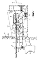
- the transport mechanism for cartridge magazines 19 shown in FIGS. 1 to 3 is Part of a not shown powder powered setting tool, the one Housing, a handle connected to the housing, one in the handle arranged, pivotable about an axis of rotation 18 trigger 6, one around a fixed in Housing arranged, second bearing point pivotable transport lever 7 and a a arranged on the transport lever 7, first bearing point 15 pivotable transmission element 13 has.
- the transmission element 13 is against the force of a Spring element 16 pivotable. In a starting position of the transmission element 13 this rests against a stop 17 of the housing.
- the distance L1 between the first bearing 15 on the transport lever 7 and the second bearing 8 around which the transport lever 7 can be pivoted corresponds to 0.15 up to 0.5 times the distance L2 between the second bearing 8 and a driving claw 12 of the transport lever 7.
- the transport lever 7 is essentially U-shaped, the second bearing 8 and in the end region of a first longer leg
- the driving claw 12 is arranged in the end region of a second, shorter leg. This take-away claw 12 engages in catches 20 of the cartridge magazine 19 and thus guides the Forward movement.
- the first bearing 15 is located on one, the second Bearing 8 opposite end portion of the first leg.
- the transmission element 13 tapers towards its free end and penetrates with it its tapered area, a passage opening of a carrier, not shown 23, on which the trigger 6 is attached.
- the tapered is inside this passage opening Area of the transmission element 13 parallel to the longitudinal extent of the cartridge magazine 19 removable.
- the transmission element 13 has a stop edge 14 which is in a pressed Position of the trigger 6, according to FIG. 3, in a form-fitting manner with a stop shoulder 22 a locking lever 9 cooperates.
- the locking lever 9 is fixed in the housing arranged, third bearing point 21 pivotable against the force of a spring 11.
- On a the stop shoulder 22 opposite side of the locking lever 9 is one Control contour 10 with a projection 3 or a notch 4 of a control element 2 cooperates, which is arranged axially fixed on a pressure pin 1.
- This Pressure pin 1 is parallel to the direction of actuation of trigger 6 with respect to the force a compression spring 5 displaceable.
- the compression spring 5 closes against Actuating direction of the trigger 6 on the control element 2 and surrounds the Contact pin 1.
- the control element 2 arranged on the pressure pin 1 gives the locking lever 9 and this releases the transmission element 13 so that it is released from the spring element 16 can be returned to its original position and the one with the Transmission element 13 cooperating transport lever 7 using the Cartridge transport spring 24 can perform its transport movement.
Landscapes
- Engineering & Computer Science (AREA)
- Mechanical Engineering (AREA)
- General Engineering & Computer Science (AREA)
- Chemical & Material Sciences (AREA)
- Combustion & Propulsion (AREA)
- Portable Nailing Machines And Staplers (AREA)
- Fertilizing (AREA)
- Catching Or Destruction (AREA)
- Percussion Or Vibration Massage (AREA)
- Thermotherapy And Cooling Therapy Devices (AREA)
Applications Claiming Priority (2)
| Application Number | Priority Date | Filing Date | Title |
|---|---|---|---|
| DE19901268A DE19901268A1 (de) | 1999-01-15 | 1999-01-15 | Pulverkraftbetriebenes Setzgerät |
| DE19901268 | 1999-01-15 |
Publications (3)
| Publication Number | Publication Date |
|---|---|
| EP1020256A2 true EP1020256A2 (fr) | 2000-07-19 |
| EP1020256A3 EP1020256A3 (fr) | 2000-07-26 |
| EP1020256B1 EP1020256B1 (fr) | 2003-10-01 |
Family
ID=7894289
Family Applications (1)
| Application Number | Title | Priority Date | Filing Date |
|---|---|---|---|
| EP99811148A Expired - Lifetime EP1020256B1 (fr) | 1999-01-15 | 1999-12-13 | Outil de scellement actionné par poudre |
Country Status (8)
| Country | Link |
|---|---|
| US (1) | US6272782B1 (fr) |
| EP (1) | EP1020256B1 (fr) |
| JP (1) | JP2000210882A (fr) |
| KR (1) | KR20000076467A (fr) |
| AT (1) | ATE251014T1 (fr) |
| CA (1) | CA2295398C (fr) |
| DE (2) | DE19901268A1 (fr) |
| PL (1) | PL190980B1 (fr) |
Families Citing this family (26)
| Publication number | Priority date | Publication date | Assignee | Title |
|---|---|---|---|---|
| US6547120B1 (en) | 2000-10-12 | 2003-04-15 | Illinois Tool Works Inc. | Powder driven fastener setting tool |
| US6981630B2 (en) * | 2000-10-12 | 2006-01-03 | Illinois Tool Works Inc. | Cartridge strip advancing mechanism for fastener driving tool |
| DE20119463U1 (de) * | 2001-11-29 | 2002-01-24 | Hilti Ag, Schaan | Tragbares, brennkraftbetriebenes Setzgerät für Befestigungselemente |
| US6974064B1 (en) * | 2003-12-05 | 2005-12-13 | Yong Song Hardware & Tool Co., Ltd. | Device for discharging a nail by the force of an explosive |
| DE10360371A1 (de) * | 2003-12-22 | 2005-07-28 | Hilti Ag | Brennkraftbetriebenes Setzgerät |
| JP5360692B2 (ja) * | 2010-03-31 | 2013-12-04 | 日立工機株式会社 | 燃焼式打込機 |
| KR101216260B1 (ko) | 2010-06-04 | 2012-12-28 | 현대위아 주식회사 | 박격포용 격발조립체 |
| CN105492721B (zh) | 2013-08-26 | 2018-10-02 | 德国德力能有限公司 | 射孔枪和雷管组件 |
| US11123851B2 (en) | 2017-10-27 | 2021-09-21 | Illinois Tool Works Inc. | Tool with charge advance mechanism |
| AU2018250391B2 (en) | 2017-10-27 | 2024-09-26 | Illinois Tool Works Inc. | Tool with charge advance mechanism |
| US11408279B2 (en) | 2018-08-21 | 2022-08-09 | DynaEnergetics Europe GmbH | System and method for navigating a wellbore and determining location in a wellbore |
| US11434713B2 (en) | 2018-05-31 | 2022-09-06 | DynaEnergetics Europe GmbH | Wellhead launcher system and method |
| US11808093B2 (en) | 2018-07-17 | 2023-11-07 | DynaEnergetics Europe GmbH | Oriented perforating system |
| US11578549B2 (en) | 2019-05-14 | 2023-02-14 | DynaEnergetics Europe GmbH | Single use setting tool for actuating a tool in a wellbore |
| US11255147B2 (en) | 2019-05-14 | 2022-02-22 | DynaEnergetics Europe GmbH | Single use setting tool for actuating a tool in a wellbore |
| US12241326B2 (en) | 2019-05-14 | 2025-03-04 | DynaEnergetics Europe GmbH | Single use setting tool for actuating a tool in a wellbore |
| US10927627B2 (en) | 2019-05-14 | 2021-02-23 | DynaEnergetics Europe GmbH | Single use setting tool for actuating a tool in a wellbore |
| US11204224B2 (en) | 2019-05-29 | 2021-12-21 | DynaEnergetics Europe GmbH | Reverse burn power charge for a wellbore tool |
| WO2021063920A1 (fr) | 2019-10-01 | 2021-04-08 | DynaEnergetics Europe GmbH | Charge d'alimentation façonnée à allumeur intégré |
| US11946728B2 (en) | 2019-12-10 | 2024-04-02 | DynaEnergetics Europe GmbH | Initiator head with circuit board |
| US11732556B2 (en) | 2021-03-03 | 2023-08-22 | DynaEnergetics Europe GmbH | Orienting perforation gun assembly |
| US12000267B2 (en) | 2021-09-24 | 2024-06-04 | DynaEnergetics Europe GmbH | Communication and location system for an autonomous frack system |
| WO2023200984A1 (fr) | 2022-04-15 | 2023-10-19 | Dbk Industries, Llc | Outil de réglage à volume fixe |
| CN115235290B (zh) * | 2022-07-07 | 2023-12-29 | 中国人民解放军91404部队第340所 | 舰上反无人机机枪和支撑底座 |
| WO2024013338A1 (fr) | 2022-07-13 | 2024-01-18 | DynaEnergetics Europe GmbH | Outil de libération de câble entraîné par gaz |
| US11753889B1 (en) | 2022-07-13 | 2023-09-12 | DynaEnergetics Europe GmbH | Gas driven wireline release tool |
Family Cites Families (5)
| Publication number | Priority date | Publication date | Assignee | Title |
|---|---|---|---|---|
| DE1072516B (de) * | 1958-03-21 | 1959-12-31 | zugl | Automatische Schußwaffe, insbesondere für rückstoßschwache Munition |
| DE2044920A1 (de) * | 1970-09-11 | 1972-03-16 | Tornado Gmbh, 4032 Lintorf | Bolzensetzgerät mit Kartuschenmagazin |
| DE2607436C2 (de) * | 1976-02-24 | 1986-10-02 | Hilti Ag, Schaan | Pulverkraftbetriebenes Setzgerät mit axial verschiebbarem Lauf |
| US4375269A (en) * | 1980-06-12 | 1983-03-01 | Olin Corporation | Disk-indexing mechanism for powder-actuated tool abstract of the disclosure |
| US4821938A (en) * | 1987-11-25 | 1989-04-18 | Haytayan Harry M | Powder-actuated fastener driving tool |
-
1999
- 1999-01-15 DE DE19901268A patent/DE19901268A1/de not_active Withdrawn
- 1999-12-13 DE DE59907188T patent/DE59907188D1/de not_active Expired - Lifetime
- 1999-12-13 EP EP99811148A patent/EP1020256B1/fr not_active Expired - Lifetime
- 1999-12-13 AT AT99811148T patent/ATE251014T1/de not_active IP Right Cessation
-
2000
- 2000-01-07 US US09/479,612 patent/US6272782B1/en not_active Expired - Lifetime
- 2000-01-13 PL PL337821A patent/PL190980B1/pl unknown
- 2000-01-13 CA CA002295398A patent/CA2295398C/fr not_active Expired - Fee Related
- 2000-01-14 KR KR1020000001791A patent/KR20000076467A/ko not_active Withdrawn
- 2000-01-17 JP JP7446A patent/JP2000210882A/ja active Pending
Non-Patent Citations (1)
| Title |
|---|
| Technischen Zeichnung für das Bolzenschubgeraät BSG II |
Also Published As
| Publication number | Publication date |
|---|---|
| DE59907188D1 (de) | 2003-11-06 |
| EP1020256B1 (fr) | 2003-10-01 |
| EP1020256A3 (fr) | 2000-07-26 |
| KR20000076467A (ko) | 2000-12-26 |
| PL337821A1 (en) | 2000-07-17 |
| CA2295398C (fr) | 2006-10-10 |
| PL190980B1 (pl) | 2006-02-28 |
| CA2295398A1 (fr) | 2000-07-15 |
| ATE251014T1 (de) | 2003-10-15 |
| US6272782B1 (en) | 2001-08-14 |
| JP2000210882A (ja) | 2000-08-02 |
| DE19901268A1 (de) | 2000-07-20 |
Similar Documents
| Publication | Publication Date | Title |
|---|---|---|
| EP1020256B1 (fr) | Outil de scellement actionné par poudre | |
| EP0835726B1 (fr) | Outil de scellement actionné par poudre avec magasin pour éléments de fixation | |
| DE69612695T2 (de) | Sicherheitsvorrichtung für eine Nagelmaschine | |
| DE3021884C2 (fr) | ||
| EP1785232B1 (fr) | Dispositif de guidage des éléments de fixation pour les outils motorisés | |
| DE2546696C3 (de) | Medizinisches Klammerinstrument zum Verschließen von schlauchförmigen organischen Gebilden, wie Blutgefäßen | |
| DE4340570C2 (de) | Eintreibvorrichtung zum Setzen von Befestigungselementen in Aufnahmematerialien | |
| DE4211276C2 (de) | Haltevorrichtung zum Halten, Führen und Freigeben eines Fügeteils, wie z.B. einer Mutter | |
| DE8534353U1 (de) | Modulares Werkzeug zum Eintreiben von Befestigungselementen | |
| DE7916804U1 (de) | Bolzensetzeinrichtung | |
| EP2127816A2 (fr) | Dispositif d'enfoncement manuel entraîné de manière électrique | |
| DE2221723B2 (de) | Muskelkraftbetriebenes tragbares Heftwerkzeug, insbesondere für Heftklammern, Nägel o.dgl | |
| DE10351419B4 (de) | Setzgerät | |
| EP0972951B1 (fr) | Outil de pose avec magasin de clous | |
| DE4122873A1 (de) | Pulverkraftbetriebenes setzgeraet mit magazin fuer befestigungselemente | |
| DE19707235A1 (de) | Setzgerät mit Magazin für Befestigungselemente | |
| DE3038565C2 (de) | Heftapparat | |
| DE19755407B4 (de) | Setzgerät | |
| DE19903993A1 (de) | Setzgerät | |
| DE19749027B4 (de) | Setzgerät | |
| DE10259777B4 (de) | Brennkraftbetriebenes Arbeitsgerät, insbesondere Setzgerät für Befestigungselemente | |
| DE1628027B2 (de) | Einrichtung zum Verriegeln des Maga zins an einem Handgerat zum Eintreiben von Befestigungsmitteln | |
| DE19805442A1 (de) | Setzgerät | |
| EP1862262A1 (fr) | Outil de scellement | |
| DE10360371A1 (de) | Brennkraftbetriebenes Setzgerät |
Legal Events
| Date | Code | Title | Description |
|---|---|---|---|
| PUAI | Public reference made under article 153(3) epc to a published international application that has entered the european phase |
Free format text: ORIGINAL CODE: 0009012 |
|
| PUAL | Search report despatched |
Free format text: ORIGINAL CODE: 0009013 |
|
| AK | Designated contracting states |
Kind code of ref document: A2 Designated state(s): AT BE CH CY DE DK ES FI FR GB GR IE IT LI LU MC NL PT SE |
|
| AX | Request for extension of the european patent |
Free format text: AL;LT;LV;MK;RO;SI |
|
| AK | Designated contracting states |
Kind code of ref document: A3 Designated state(s): AT BE CH CY DE DK ES FI FR GB GR IE IT LI LU MC NL PT SE |
|
| AX | Request for extension of the european patent |
Free format text: AL;LT;LV;MK;RO;SI |
|
| RIC1 | Information provided on ipc code assigned before grant |
Free format text: 7B 25C 1/14 A, 7B 25C 1/18 B |
|
| 17P | Request for examination filed |
Effective date: 20010126 |
|
| AKX | Designation fees paid |
Free format text: AT BE CH CY DE DK ES FI FR GB GR IE IT LI LU MC NL PT SE |
|
| GRAH | Despatch of communication of intention to grant a patent |
Free format text: ORIGINAL CODE: EPIDOS IGRA |
|
| TPAD | Observations filed by third parties |
Free format text: ORIGINAL CODE: EPIDOS TIPA |
|
| GRAS | Grant fee paid |
Free format text: ORIGINAL CODE: EPIDOSNIGR3 |
|
| GRAA | (expected) grant |
Free format text: ORIGINAL CODE: 0009210 |
|
| AK | Designated contracting states |
Kind code of ref document: B1 Designated state(s): AT BE CH CY DE DK ES FI FR GB GR IE IT LI LU MC NL PT SE |
|
| PG25 | Lapsed in a contracting state [announced via postgrant information from national office to epo] |
Ref country code: IT Free format text: LAPSE BECAUSE OF FAILURE TO SUBMIT A TRANSLATION OF THE DESCRIPTION OR TO PAY THE FEE WITHIN THE PRESCRIBED TIME-LIMIT;WARNING: LAPSES OF ITALIAN PATENTS WITH EFFECTIVE DATE BEFORE 2007 MAY HAVE OCCURRED AT ANY TIME BEFORE 2007. THE CORRECT EFFECTIVE DATE MAY BE DIFFERENT FROM THE ONE RECORDED. Effective date: 20031001 Ref country code: IE Free format text: LAPSE BECAUSE OF FAILURE TO SUBMIT A TRANSLATION OF THE DESCRIPTION OR TO PAY THE FEE WITHIN THE PRESCRIBED TIME-LIMIT Effective date: 20031001 Ref country code: FI Free format text: LAPSE BECAUSE OF FAILURE TO SUBMIT A TRANSLATION OF THE DESCRIPTION OR TO PAY THE FEE WITHIN THE PRESCRIBED TIME-LIMIT Effective date: 20031001 |
|
| REG | Reference to a national code |
Ref country code: GB Ref legal event code: FG4D Free format text: NOT ENGLISH |
|
| REG | Reference to a national code |
Ref country code: SE Ref legal event code: TRGR |
|
| REG | Reference to a national code |
Ref country code: CH Ref legal event code: EP |
|
| REG | Reference to a national code |
Ref country code: IE Ref legal event code: FG4D Free format text: GERMAN |
|
| REF | Corresponds to: |
Ref document number: 59907188 Country of ref document: DE Date of ref document: 20031106 Kind code of ref document: P |
|
| PG25 | Lapsed in a contracting state [announced via postgrant information from national office to epo] |
Ref country code: LU Free format text: LAPSE BECAUSE OF NON-PAYMENT OF DUE FEES Effective date: 20031213 Ref country code: CY Free format text: LAPSE BECAUSE OF FAILURE TO SUBMIT A TRANSLATION OF THE DESCRIPTION OR TO PAY THE FEE WITHIN THE PRESCRIBED TIME-LIMIT Effective date: 20031213 |
|
| PG25 | Lapsed in a contracting state [announced via postgrant information from national office to epo] |
Ref country code: MC Free format text: LAPSE BECAUSE OF NON-PAYMENT OF DUE FEES Effective date: 20031231 Ref country code: LI Free format text: LAPSE BECAUSE OF NON-PAYMENT OF DUE FEES Effective date: 20031231 Ref country code: CH Free format text: LAPSE BECAUSE OF NON-PAYMENT OF DUE FEES Effective date: 20031231 |
|
| PG25 | Lapsed in a contracting state [announced via postgrant information from national office to epo] |
Ref country code: GR Free format text: LAPSE BECAUSE OF FAILURE TO SUBMIT A TRANSLATION OF THE DESCRIPTION OR TO PAY THE FEE WITHIN THE PRESCRIBED TIME-LIMIT Effective date: 20040101 Ref country code: DK Free format text: LAPSE BECAUSE OF FAILURE TO SUBMIT A TRANSLATION OF THE DESCRIPTION OR TO PAY THE FEE WITHIN THE PRESCRIBED TIME-LIMIT Effective date: 20040101 |
|
| GBT | Gb: translation of ep patent filed (gb section 77(6)(a)/1977) |
Effective date: 20031217 |
|
| PG25 | Lapsed in a contracting state [announced via postgrant information from national office to epo] |
Ref country code: ES Free format text: LAPSE BECAUSE OF FAILURE TO SUBMIT A TRANSLATION OF THE DESCRIPTION OR TO PAY THE FEE WITHIN THE PRESCRIBED TIME-LIMIT Effective date: 20040112 |
|
| REG | Reference to a national code |
Ref country code: IE Ref legal event code: FD4D |
|
| ET | Fr: translation filed | ||
| PLBE | No opposition filed within time limit |
Free format text: ORIGINAL CODE: 0009261 |
|
| STAA | Information on the status of an ep patent application or granted ep patent |
Free format text: STATUS: NO OPPOSITION FILED WITHIN TIME LIMIT |
|
| REG | Reference to a national code |
Ref country code: CH Ref legal event code: PL |
|
| 26N | No opposition filed |
Effective date: 20040702 |
|
| PGFP | Annual fee paid to national office [announced via postgrant information from national office to epo] |
Ref country code: NL Payment date: 20041205 Year of fee payment: 6 |
|
| PGFP | Annual fee paid to national office [announced via postgrant information from national office to epo] |
Ref country code: SE Payment date: 20041206 Year of fee payment: 6 |
|
| PGFP | Annual fee paid to national office [announced via postgrant information from national office to epo] |
Ref country code: AT Payment date: 20041213 Year of fee payment: 6 |
|
| PGFP | Annual fee paid to national office [announced via postgrant information from national office to epo] |
Ref country code: GB Payment date: 20051207 Year of fee payment: 7 |
|
| PG25 | Lapsed in a contracting state [announced via postgrant information from national office to epo] |
Ref country code: AT Free format text: LAPSE BECAUSE OF NON-PAYMENT OF DUE FEES Effective date: 20051213 |
|
| PG25 | Lapsed in a contracting state [announced via postgrant information from national office to epo] |
Ref country code: SE Free format text: LAPSE BECAUSE OF NON-PAYMENT OF DUE FEES Effective date: 20051214 |
|
| PGFP | Annual fee paid to national office [announced via postgrant information from national office to epo] |
Ref country code: BE Payment date: 20060217 Year of fee payment: 7 |
|
| PG25 | Lapsed in a contracting state [announced via postgrant information from national office to epo] |
Ref country code: NL Free format text: LAPSE BECAUSE OF NON-PAYMENT OF DUE FEES Effective date: 20060701 |
|
| EUG | Se: european patent has lapsed | ||
| NLV4 | Nl: lapsed or anulled due to non-payment of the annual fee |
Effective date: 20060701 |
|
| PG25 | Lapsed in a contracting state [announced via postgrant information from national office to epo] |
Ref country code: BE Free format text: LAPSE BECAUSE OF NON-PAYMENT OF DUE FEES Effective date: 20061231 |
|
| GBPC | Gb: european patent ceased through non-payment of renewal fee |
Effective date: 20061213 |
|
| PG25 | Lapsed in a contracting state [announced via postgrant information from national office to epo] |
Ref country code: GB Free format text: LAPSE BECAUSE OF NON-PAYMENT OF DUE FEES Effective date: 20061213 |
|
| BERE | Be: lapsed |
Owner name: *HILTI A.G. Effective date: 20061231 |
|
| PG25 | Lapsed in a contracting state [announced via postgrant information from national office to epo] |
Ref country code: PT Free format text: LAPSE BECAUSE OF NON-PAYMENT OF DUE FEES Effective date: 20040301 |
|
| PGFP | Annual fee paid to national office [announced via postgrant information from national office to epo] |
Ref country code: DE Payment date: 20131211 Year of fee payment: 15 |
|
| PGFP | Annual fee paid to national office [announced via postgrant information from national office to epo] |
Ref country code: FR Payment date: 20131209 Year of fee payment: 15 |
|
| REG | Reference to a national code |
Ref country code: DE Ref legal event code: R119 Ref document number: 59907188 Country of ref document: DE |
|
| REG | Reference to a national code |
Ref country code: FR Ref legal event code: ST Effective date: 20150831 |
|
| PG25 | Lapsed in a contracting state [announced via postgrant information from national office to epo] |
Ref country code: DE Free format text: LAPSE BECAUSE OF NON-PAYMENT OF DUE FEES Effective date: 20150701 |
|
| PG25 | Lapsed in a contracting state [announced via postgrant information from national office to epo] |
Ref country code: FR Free format text: LAPSE BECAUSE OF NON-PAYMENT OF DUE FEES Effective date: 20141231 |