EP1020334A2 - Guide-cable pour un prétensionneur pyrotechnique - Google Patents
Guide-cable pour un prétensionneur pyrotechnique Download PDFInfo
- Publication number
- EP1020334A2 EP1020334A2 EP00100356A EP00100356A EP1020334A2 EP 1020334 A2 EP1020334 A2 EP 1020334A2 EP 00100356 A EP00100356 A EP 00100356A EP 00100356 A EP00100356 A EP 00100356A EP 1020334 A2 EP1020334 A2 EP 1020334A2
- Authority
- EP
- European Patent Office
- Prior art keywords
- rope
- guide element
- ignition
- cavity
- cable guide
- Prior art date
- Legal status (The legal status is an assumption and is not a legal conclusion. Google has not performed a legal analysis and makes no representation as to the accuracy of the status listed.)
- Withdrawn
Links
Images

Classifications
-
- B—PERFORMING OPERATIONS; TRANSPORTING
- B60—VEHICLES IN GENERAL
- B60R—VEHICLES, VEHICLE FITTINGS, OR VEHICLE PARTS, NOT OTHERWISE PROVIDED FOR
- B60R22/00—Safety belts or body harnesses in vehicles
- B60R22/18—Anchoring devices
- B60R22/195—Anchoring devices with means to tension the belt in an emergency, e.g. means of the through-anchor or splitted reel type
- B60R22/1952—Transmission of tensioning power by cable; Return motion locking means therefor
Definitions
- the invention relates to a cable guide element for insertion into the tubular cylinder a pyrotechnic belt tensioner with at least one axial rope through hole.
- Known pyrotechnic belt tensioners have a traction rope that has a Rope deflection is connected to a belt link on which about a Belt buckle is attached.
- a tubular cylinder is attached to the cable deflection a piston is slidably disposed.
- Between the rope deflection and the A cable guide element is attached to the piston inside the tubular cylinder.
- the Cable guide element is in the longitudinal direction of the tubular cylinder with at least provided with a rope through hole. It also has a room into which a Gas generator is used. The room is connected to the pressure room via an opening in connection.
- One end of the pull rope is through the rope through hole in the Pipe cylinder guided and attached to the piston.
- the piston is from one Normal position can be shifted into a tension holding position, in which he tensions the pull rope, so that it tightens a belt. There is a backstop on the piston Can hold the piston in the tightening position.
- the propellant becomes the gas generator ignited and flows explosively into the pressure chamber.
- the piston is under the pressure of the inflowing propellant shifted into the taut holding position.
- DE-296 04 482 U1 describes the rope guiding element of a pyrotechnic Belt tensioners known.
- This known rope guide element is in the tubular cylinder of the belt tensioner in the axial direction of the tube offset to one in the tube slidable piston arranged. It has a recess into which one Propellant cartridge is inserted, and at least one in the remaining area axially running rope through hole for guiding a traction rope on the cartridge past.
- a disadvantage of the known cable guide element is that in it the space available for receiving the cartridge because of its given shape is not used well, so that the cable guide element and so that the tube cylinder is unnecessarily long.
- the object of the invention is to provide a cable guide element of the type mentioned to build more compact.
- This task is performed in the rope guide element of the type mentioned according to the invention by a closable cavity in the cable guide element solved with a propellant charge in the cavity and with one in the Propellant protruding ignition device.
- the advantages of the invention are in particular an improvement in the use of space and a resulting shortening of the cable guide element and simplifying its construction.
- the longitudinal axis of the cavity is advantageously parallel to the rope through hole arranged; the cable guide element is in an elongated shape is formed and can be particularly firmly in the tube cylinder of the belt tensioner anchor.
- the ignition device contains one Ignition charge in an ignition chamber, the ignition charge from the propellant charge separating fragile separating element and an ignition path located in the priming charge, whose ignition contacts by means of connecting elements that come from the cable guide element are brought out.
- the ignition device can be used as a functional unit insert the cable guide element before filling with the propellant charge.
- an electrical circuit for example a low pass, connected to the connecting organs to pass through at random to suppress any stray fields and induced voltage peaks prevent accidental ignition.
- the ignition device protrudes through a Bore in a first end face of the cavity, and a second The end face, which is opposite the first end face, has a fragile closure element locked.
- This arrangement simplifies the manufacture of the Rope guide element especially when the ignition device is functional is prefabricated because it is pushed through the second end face and the cavity to close the hole in the first face.
- the cavity is filled with the propellant charge and with a fragile closure element closed on the second face.
- the cable guide element advantageously has a cylindrical outer contour, whose outer diameter is approximately the inner diameter of the tubular cylinder corresponds to a particularly secure and stable hold of the cable guide element due to its positive and possibly frictional contact with the inside walls of the Pipe cylinder is given.
- the cylindrical cable guide element is made of composed of several separate element sections.
- Such Embodiment may be in terms of manufacturing technology and / or advantageous in terms of the strength of the cable guide element.
- the cable guide element or the element sections are preferred Made of plastic material.
- the plastic material is cast, for example or injected and preferably has one for attachment inside the Pipe cylinder suitable shape; furthermore, for example, the connecting elements and other parts of the ignition device directly surrounded by plastic.
- a belt tensioner with a piston, which is driven by a propellant in the event of a Accident is linearly displaceable in a tubular cylinder and with at least one Connected rope, which is retractable by moving the piston, has a cable guide element in the tubular cylinder, that preferably according to the invention is trained.
- the advantage of such a pretensioner is one particular compact structure so that it can be installed more flexibly in a vehicle.
- Fig. 1 is a belt tensioner with a belt link 2, on which a belt buckle is attached, a cable deflection 8, and a tubular cylinder 10 and one in the Tube cylinder 10 displaceable piston 1 shown.
- the belt link 2 is with the piston 1 via an extensible pull rope 150 laid in two strands connected, which with a loop around a pin 50 of the belt link 2 is laid. Furthermore, the pull rope 150 is through a channel of a rope deflection 8 and then through rope through holes 5 of a rope guide element 140 performed, which is arranged in the tubular cylinder 10.
- the tube cylinder 10 is on the Rope deflection 8 attached.
- the traction cable 150 is encased by a bellows 4.
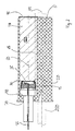
- Tube cylinder 10 is a pressure chamber between the end wall 45 and the piston 1 26 provided. A fragile separating element closes the pressure chamber 26 Rope lead-through element on its end face 45.
- a cavity 110 is provided, which with Propellant charge 120 is filled.
- the igniter 15 is about a connector 35, for example Ignition cable, which through the end wall 40 and then through a Through opening in the cable deflection 8 is guided to the outside, with a Sensor (not shown) connected.
- a second section - shown in the drawing in the upper area - extends also extends over the longitudinal extent of the cable guide element the cavity 110.
- the longitudinal axis 60 of the cavity 110 runs parallel to the Longitudinal axis 55 of the rope through hole 5 and parallel to the longitudinal axis 65 of the Rope guide element.
- the cavity 110 has a first end face 40, and opposite this an opening with a fragile closure element 45 is closed and the ignition device 15 and the propellant charge.
- the Ignition device 15 is located in the cavity 110 and is located on the end face 40 of the cavity and protrudes through a bore 70 with a reduced cross section in the tube cylinder 10 into it.
- the ignition contacts 30 of the ignition device 15 are located itself in cavity 110 and are of an ignition charge in an ignition chamber surrounded by a fragile separating element 25.
- the ignition contacts 30 are connected to connecting members 35 which are outside the cable guide element for connection to a motion sensor or the like. are exposed, cf. Fig. 1.
Landscapes
- Engineering & Computer Science (AREA)
- Mechanical Engineering (AREA)
- Automotive Seat Belt Assembly (AREA)
- Ropes Or Cables (AREA)
- Emergency Lowering Means (AREA)
Applications Claiming Priority (2)
| Application Number | Priority Date | Filing Date | Title |
|---|---|---|---|
| DE29900341U DE29900341U1 (de) | 1999-01-12 | 1999-01-12 | Seilführungselement für einen pyrotechnischen Gurtstraffer |
| DE29900341U | 1999-01-12 |
Publications (2)
| Publication Number | Publication Date |
|---|---|
| EP1020334A2 true EP1020334A2 (fr) | 2000-07-19 |
| EP1020334A3 EP1020334A3 (fr) | 2003-09-24 |
Family
ID=8067810
Family Applications (1)
| Application Number | Title | Priority Date | Filing Date |
|---|---|---|---|
| EP00100356A Withdrawn EP1020334A3 (fr) | 1999-01-12 | 2000-01-07 | Guide-cable pour un prétensionneur pyrotechnique |
Country Status (2)
| Country | Link |
|---|---|
| EP (1) | EP1020334A3 (fr) |
| DE (1) | DE29900341U1 (fr) |
Cited By (1)
| Publication number | Priority date | Publication date | Assignee | Title |
|---|---|---|---|---|
| WO2004096615A1 (fr) * | 2003-05-02 | 2004-11-11 | Autoliv Development Ab | Tendeur de ceinture de securite monte dans un vehicule automobile |
Citations (1)
| Publication number | Priority date | Publication date | Assignee | Title |
|---|---|---|---|---|
| DE29604482U1 (de) | 1996-02-13 | 1996-05-02 | Hirtenberger Präzisionstechnik GmbH, Hirtenberg | Pyrotechnischer Gurtstraffer |
Family Cites Families (5)
| Publication number | Priority date | Publication date | Assignee | Title |
|---|---|---|---|---|
| DE3215926C2 (de) * | 1982-04-29 | 1985-09-19 | Bayern-Chemie Gesellschaft für flugchemische Antriebe mbH, 8261 Aschau | Aufwickelvorrichtung mit Rückstrammer für Sicherheitsgurte in Fahrzeugen |
| DE4332205C2 (de) * | 1993-09-22 | 2000-06-15 | Hs Tech & Design | Dreipunkt-Sicherheitsgurtsystem für ein Kraftfahrzeug |
| DE4404462A1 (de) * | 1994-02-11 | 1995-08-17 | Trw Repa Gmbh | Gurtstraffer für einen Sicherheitsgurt |
| DE29609054U1 (de) * | 1996-05-20 | 1996-09-19 | Trw Occupant Restraint Systems Gmbh, 73551 Alfdorf | Gurtstraffer für ein Fahrzeuginsassen-Rückhaltesystem |
| DE29900178U1 (de) * | 1999-01-08 | 1999-03-18 | E. Dittrich KG "Schlüssel"-Erzeugnisse, 28307 Bremen | Gurtstraffer |
-
1999
- 1999-01-12 DE DE29900341U patent/DE29900341U1/de not_active Expired - Lifetime
-
2000
- 2000-01-07 EP EP00100356A patent/EP1020334A3/fr not_active Withdrawn
Patent Citations (1)
| Publication number | Priority date | Publication date | Assignee | Title |
|---|---|---|---|---|
| DE29604482U1 (de) | 1996-02-13 | 1996-05-02 | Hirtenberger Präzisionstechnik GmbH, Hirtenberg | Pyrotechnischer Gurtstraffer |
Cited By (1)
| Publication number | Priority date | Publication date | Assignee | Title |
|---|---|---|---|---|
| WO2004096615A1 (fr) * | 2003-05-02 | 2004-11-11 | Autoliv Development Ab | Tendeur de ceinture de securite monte dans un vehicule automobile |
Also Published As
| Publication number | Publication date |
|---|---|
| DE29900341U1 (de) | 1999-04-22 |
| EP1020334A3 (fr) | 2003-09-24 |
Similar Documents
| Publication | Publication Date | Title |
|---|---|---|
| DE102014002006B4 (de) | Straffer für eine Fahrzeugsicherheitseinrichtung | |
| DE69533421T2 (de) | Geformter gegenstand mit integralem verschiebbarem element oder elementen und verfahren zu dessen/deren verwendung | |
| DE4332206C2 (de) | Antriebsvorrichtung | |
| DE1515407B2 (fr) | ||
| DE4222985A1 (de) | Linearantrieb für einen Gurtstraffer | |
| EP0558963A2 (fr) | Dispositif tendeur linéaire pour un système de retenue dans un véhicule | |
| DE4415373A1 (de) | Gasgenerator für ein Fahrzeug-Rückhaltesystem | |
| DE102006015706A1 (de) | Gurtstraffer mit integriertem Gaserzeuger | |
| EP1034990A2 (fr) | Prétensionneur de ceinture avec ensemble piston-cylindre et tige coulissante | |
| EP0147661A1 (fr) | Source d'énergie mécanique activée par gaz sous pression | |
| DE69408646T2 (de) | Nachstellvorrichtung für einen Bowdenzug | |
| DE2947752A1 (de) | Kunststoffduebel | |
| AT1187U1 (de) | Pyrotechnischer gurtstraffer | |
| EP1020334A2 (fr) | Guide-cable pour un prétensionneur pyrotechnique | |
| EP0869041A2 (fr) | Rétracteur de boucle pour un système de ceinture de sécurité | |
| DE102012002719B4 (de) | Pyrotechnischer Straffer | |
| EP0806626A2 (fr) | Allumeur électrique pour un générateur de gaz pyrotechnique | |
| EP1274611B1 (fr) | Dispositif sac gonflable et son procede de fonctionnement | |
| DE2946717A1 (de) | Vorrichtung zum spannen eines gurts | |
| EP1018456A2 (fr) | Générateur de gaz à composant électrique intégré | |
| DE102020107175B4 (de) | In einem Sitzrohr befestigbare Straffvorrichtung, Sitzrohr, Fahrzeugsitz und Verfahren zur Montage einer Straffvorrichtung | |
| DE10308121B3 (de) | Exzenterklinke für eine Sicherheitsgurt-Strammeinrichtung | |
| DE10227755B4 (de) | Pyrotechnischer Schloßstraffer | |
| DE10319714B4 (de) | Gurtstraffer an einem Kraftfahrzeug | |
| DE10341799B4 (de) | Spannelement mit Führungsarmen |
Legal Events
| Date | Code | Title | Description |
|---|---|---|---|
| PUAI | Public reference made under article 153(3) epc to a published international application that has entered the european phase |
Free format text: ORIGINAL CODE: 0009012 |
|
| AK | Designated contracting states |
Kind code of ref document: A2 Designated state(s): AT BE CH CY DE DK ES FI FR GB GR IE IT LI LU MC NL PT SE |
|
| AX | Request for extension of the european patent |
Free format text: AL;LT;LV;MK;RO;SI |
|
| PUAJ | Public notification under rule 129 epc |
Free format text: ORIGINAL CODE: 0009425 |
|
| PUAL | Search report despatched |
Free format text: ORIGINAL CODE: 0009013 |
|
| AK | Designated contracting states |
Kind code of ref document: A3 Designated state(s): AT BE CH CY DE DK ES FI FR GB GR IE IT LI LU MC NL PT SE |
|
| AX | Request for extension of the european patent |
Extension state: AL LT LV MK RO SI |
|
| STAA | Information on the status of an ep patent application or granted ep patent |
Free format text: STATUS: THE APPLICATION IS DEEMED TO BE WITHDRAWN |
|
| 18D | Application deemed to be withdrawn |
Effective date: 20030801 |