EP1020391A1 - Dispositif et méthode pour alimenter une bande de matériau déroulée d'une bobine à une machine de traitement - Google Patents
Dispositif et méthode pour alimenter une bande de matériau déroulée d'une bobine à une machine de traitement Download PDFInfo
- Publication number
- EP1020391A1 EP1020391A1 EP99124513A EP99124513A EP1020391A1 EP 1020391 A1 EP1020391 A1 EP 1020391A1 EP 99124513 A EP99124513 A EP 99124513A EP 99124513 A EP99124513 A EP 99124513A EP 1020391 A1 EP1020391 A1 EP 1020391A1
- Authority
- EP
- European Patent Office
- Prior art keywords
- winding roll
- web
- material web
- deflection device
- fluctuations
- Prior art date
- Legal status (The legal status is an assumption and is not a legal conclusion. Google has not performed a legal analysis and makes no representation as to the accuracy of the status listed.)
- Granted
Links
- 238000000034 method Methods 0.000 title claims abstract description 6
- 238000004804 winding Methods 0.000 title claims description 22
- 239000000463 material Substances 0.000 claims description 17
- 230000001105 regulatory effect Effects 0.000 claims description 5
- 239000013072 incoming material Substances 0.000 claims description 2
- 230000010349 pulsation Effects 0.000 description 5
- 238000013016 damping Methods 0.000 description 2
- 230000001419 dependent effect Effects 0.000 description 2
- 238000005259 measurement Methods 0.000 description 2
- 239000011111 cardboard Substances 0.000 description 1
- 230000001276 controlling effect Effects 0.000 description 1
- 239000011888 foil Substances 0.000 description 1
- 230000003993 interaction Effects 0.000 description 1
- 239000002184 metal Substances 0.000 description 1
- 239000011087 paperboard Substances 0.000 description 1
- 239000000523 sample Substances 0.000 description 1
- 230000001960 triggered effect Effects 0.000 description 1
Images


Classifications
-
- B—PERFORMING OPERATIONS; TRANSPORTING
- B65—CONVEYING; PACKING; STORING; HANDLING THIN OR FILAMENTARY MATERIAL
- B65H—HANDLING THIN OR FILAMENTARY MATERIAL, e.g. SHEETS, WEBS, CABLES
- B65H23/00—Registering, tensioning, smoothing or guiding webs
- B65H23/04—Registering, tensioning, smoothing or guiding webs longitudinally
- B65H23/048—Registering, tensioning, smoothing or guiding webs longitudinally by positively actuated movable bars or rollers
-
- B—PERFORMING OPERATIONS; TRANSPORTING
- B65—CONVEYING; PACKING; STORING; HANDLING THIN OR FILAMENTARY MATERIAL
- B65H—HANDLING THIN OR FILAMENTARY MATERIAL, e.g. SHEETS, WEBS, CABLES
- B65H2511/00—Dimensions; Position; Numbers; Identification; Occurrences
- B65H2511/10—Size; Dimensions
- B65H2511/16—Irregularities, e.g. protuberances
- B65H2511/166—Irregularities, e.g. protuberances relative to diameter, eccentricity or circularity
Definitions
- the invention relates to a method and an apparatus for feeding one of Wound roll drawn material web to a processing machine according to the The preamble of claim 1 or claim 2.
- material webs for example paper or cardboard webs, plastic or Metal foils, continuously fed to a subsequent processing machine, these are known to be unwound from winding rolls, which are in an unwinder are attached.
- DE 37 04 677 describes a method and a device of the generic type known, in which the material web after Unwinding to compensate for length fluctuations performed around a deflection device becomes movable with a component in the direction of the incoming material web is stored.
- the deflection device is a pendulum-mounted compensating roller, the Pendulum movement is dampened by a damping cylinder, its counterforce is proportional to the web tension.
- the material web is soothed and with constant Voltage supplied to the processing machine.
- the invention is therefore based on the object of a method and an apparatus Generic type to create with the (large) changes in length high frequencies can be compensated.
- a compensation device deflecting the web is used, which are not freely movable, but by means of a controlled or regulated actuator is positioned with a component in the feed direction of the material web.
- a Measuring device determines the fluctuations in the diameter of the winding roll, and in The actuator is dependent on the measured values from a control device controlled or regulated so that the compensation device in each case in the required position is moved.
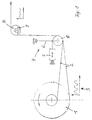
- the device according to the invention includes an unwinding device into which a Winding roll 1 is suspended for unwinding the material web 2.
- a measuring device 3 continuously measures the diameter of the winding roll 1, and a control device determines the fluctuations in diameter from the measured values, caused by out of roundness in the winding roll 1.
- the fluctuations in Diameters of the winding roll 1 lead to changes in length in the running web 2, compensated by the compensation device 4 arranged below become.
- the compensation device 4 arranged behind the unwinding device consists of a roller 5 deflecting the web 2, the position of which with a component in Feed direction of the material web 2 is changeable.
- a change in the position of the Roller 4 leads to a change in length of the railway line, with which there is a change in length the web 2 can compensate.
- the roller 5 is as in the Position changeable deflector mounted on the free end of a lever 6, the extending downward in the direction of the winding roll 1 is pivotally suspended.
- a control device For this purpose, its position is continuously determined and sent to a control device
- a hydraulic piston-cylinder unit is used as the actuator or a position-controlled linear motor is used.
- suspended roller 5 can also be a linearly movable roller or another deflecting element which can be moved linearly or along a curved path be used to change the length of the railway line.
- the load cell 9 detects the amount of tension in the web 2.
- the measurement signal is used to control the speed of the winding roll 1 and thus used for the control of the tension in the web 2.
- the roller 5 is preset to a middle position.
- the control device determines from the measurement signals of the measuring device 3 the fluctuations in the winding roll diameter and controls the actuator 7, the if necessary, the position of the roller 5 changed so that the fluctuations in the Web length can be compensated.
- the compensation system (measuring device 3, Control device, actuator 7, roller 5) is designed so dynamically that fluctuations can be compensated with a frequency of up to 8 Hz.
- FIG. 2 shows an expanded version of a device according to the invention, which an additional compensation device 10 to compensate for short pulsation waves higher frequency does not contain that of the compensation device 4 can be corrected.
- the additional compensation device 10 consists of a deflection tube 11 which a compressed air supply is connected and the pipe wall of the web 2 wrapped area has a plurality of passage openings for the compressed air.
- the web 2 is so contactless on a compressed air cushion 12 floating around the tube 11 steered.
- the height of the air cushion 12 can depend on the performance of the compressed air blower can be varied between 3 mm and 12 mm. Since the air volume under the material web 2 is almost massless, very high-frequency vibrations with small amplitude be compensated very largely.
- the interaction of the position-controlled roller 5 with the air cushion 12 allows fluctuations in the web length over a very to compensate for a wide frequency and amplitude range caused by non-roundness in the Winding roll 1 are caused.
- the pressure of the air cushion 12 is dependent on the tensile stress in the web 2, can the value advantageously as a control variable for controlling the tension in the web 2 be used.
- the pressure in the air cushion 12 is a Probe 13 measured and fed to a pressure / current converter 14. There will be a generates an appropriate electrical signal, which - as described above - for Regulation of the speed of the winding roll 1 and thus to regulate the tension in the Lane 2 is used.
- FIG. 3 shows an embodiment in which the two compensation devices 5, 10 according to FIG. 2 are combined in a single device:
- the position-controlled roller is replaced by an air tube 15 as a deflection device, the Structure corresponds to the air tube 11 according to FIG. 2, and this additionally corresponds to the roller 5 Figure 2 is changeable in its position.
- the web 2 is contactless on one Air cushion 12 guided around the pipe 15 to a subsequent deflecting roller 16 and from this is directed to the processing machine.
- the position of the air tube 15 is on the in the embodiment of Figure 1 described manner depending on the Measuring signal of the measuring device 3 controlled, that is, from the fluctuations in the diameter the winding roll 1.
- the air cushion 12 automatically compensates for high-frequency pulsations with low amplitude. In this embodiment too, the value of Pressure in the air cushion 12 used to control the tension of the web 2, as in the embodiment of Figure 3 described.
Landscapes
- Controlling Rewinding, Feeding, Winding, Or Abnormalities Of Webs (AREA)
Applications Claiming Priority (2)
| Application Number | Priority Date | Filing Date | Title |
|---|---|---|---|
| DE19900536A DE19900536A1 (de) | 1999-01-11 | 1999-01-11 | Verfahren und Vorrichtung zum Zuführen einer von einer Wickelrolle abgezogenen Materialbahn zu einer Verarbeitungsmaschine |
| DE19900536 | 1999-01-11 |
Publications (2)
| Publication Number | Publication Date |
|---|---|
| EP1020391A1 true EP1020391A1 (fr) | 2000-07-19 |
| EP1020391B1 EP1020391B1 (fr) | 2003-05-02 |
Family
ID=7893830
Family Applications (1)
| Application Number | Title | Priority Date | Filing Date |
|---|---|---|---|
| EP99124513A Expired - Lifetime EP1020391B1 (fr) | 1999-01-11 | 1999-12-09 | Dispositif et méthode pour alimenter une bande de matériau déroulée d'une bobine à une machine de traitement |
Country Status (2)
| Country | Link |
|---|---|
| EP (1) | EP1020391B1 (fr) |
| DE (2) | DE19900536A1 (fr) |
Cited By (1)
| Publication number | Priority date | Publication date | Assignee | Title |
|---|---|---|---|---|
| FR2849649A1 (fr) * | 2003-01-08 | 2004-07-09 | Komori Chambon | Appareil de faconnage a plaques interchangeables |
Citations (5)
| Publication number | Priority date | Publication date | Assignee | Title |
|---|---|---|---|---|
| US4657198A (en) * | 1984-05-18 | 1987-04-14 | Fuji Photo Film Co., Ltd. | Apparatus for measuring the thickness of a roll winding on or unwinding from a core |
| DE3704677A1 (de) * | 1986-12-27 | 1988-07-07 | Kampf Gmbh & Co Maschf | Verfahren und vorrichtung zum kantenrichtigen einfuehren einer materialbahn in eine verarbeitungsmaschine |
| DE4425355A1 (de) * | 1993-07-16 | 1995-01-26 | Siemens Ag | Regelung für den Antrieb eines Haspels |
| DE19614300A1 (de) * | 1995-04-21 | 1996-10-24 | Abb Patent Gmbh | Verfahren zur selbstregulierenden Kompensation der Auswirkung des ungleichmäßigen Rundlaufs einer Rolle |
| US5659229A (en) * | 1995-01-31 | 1997-08-19 | Kimberly-Clark Worldwide, Inc. | Controlling web tension by actively controlling velocity of dancer roll |
-
1999
- 1999-01-11 DE DE19900536A patent/DE19900536A1/de not_active Withdrawn
- 1999-12-09 DE DE59905311T patent/DE59905311D1/de not_active Expired - Fee Related
- 1999-12-09 EP EP99124513A patent/EP1020391B1/fr not_active Expired - Lifetime
Patent Citations (5)
| Publication number | Priority date | Publication date | Assignee | Title |
|---|---|---|---|---|
| US4657198A (en) * | 1984-05-18 | 1987-04-14 | Fuji Photo Film Co., Ltd. | Apparatus for measuring the thickness of a roll winding on or unwinding from a core |
| DE3704677A1 (de) * | 1986-12-27 | 1988-07-07 | Kampf Gmbh & Co Maschf | Verfahren und vorrichtung zum kantenrichtigen einfuehren einer materialbahn in eine verarbeitungsmaschine |
| DE4425355A1 (de) * | 1993-07-16 | 1995-01-26 | Siemens Ag | Regelung für den Antrieb eines Haspels |
| US5659229A (en) * | 1995-01-31 | 1997-08-19 | Kimberly-Clark Worldwide, Inc. | Controlling web tension by actively controlling velocity of dancer roll |
| DE19614300A1 (de) * | 1995-04-21 | 1996-10-24 | Abb Patent Gmbh | Verfahren zur selbstregulierenden Kompensation der Auswirkung des ungleichmäßigen Rundlaufs einer Rolle |
Cited By (1)
| Publication number | Priority date | Publication date | Assignee | Title |
|---|---|---|---|---|
| FR2849649A1 (fr) * | 2003-01-08 | 2004-07-09 | Komori Chambon | Appareil de faconnage a plaques interchangeables |
Also Published As
| Publication number | Publication date |
|---|---|
| EP1020391B1 (fr) | 2003-05-02 |
| DE19900536A1 (de) | 2000-07-13 |
| DE59905311D1 (de) | 2003-06-05 |
Similar Documents
| Publication | Publication Date | Title |
|---|---|---|
| DE3214396C2 (de) | Vorrichtung zum Aufwickeln einer Bahn, wie Papierbahn | |
| DE3114056C2 (fr) | ||
| DE69614433T2 (de) | Verfahren und Vorrichtung zum Berechnen und Regeln der Dehnung einer laufenden Materialbahn | |
| EP0026335A1 (fr) | Installation de commande pour dispositifs pour enrouler des matériaux en bande et procédé pour enrouler des matériaux en bande sensibles à la pression | |
| EP0593946A2 (fr) | Dispositif pour enrouler une bande | |
| EP0289776B1 (fr) | Dispositif pour enrouler et dérouler une bande | |
| DE3805950A1 (de) | Trenn- und wiederaufwickelvorrichtung fuer bahnen | |
| WO1991016257A1 (fr) | Procede et dispositif pour l'enroulement de bandes de materiau, en particulier les bandes de papier ou de carton | |
| WO1998055247A1 (fr) | Dispositif d'ajustement de deroulement pour materiau sous forme d'un fil ou de plusieurs fils metalliques | |
| DE10326133B4 (de) | Vorrichtung und Verfahren zum Regeln der Spannkraft eines umlaufenden Bandes | |
| DE4131760C2 (de) | Verfahren und Vorrichtung zum Regeln der Bahnzugkraft einer Textilbahn | |
| DE112006001914T5 (de) | Verfahren zum Aurollen einer Papier- oder Kartonbahn, und Rollapparat | |
| EP1020391B1 (fr) | Dispositif et méthode pour alimenter une bande de matériau déroulée d'une bobine à une machine de traitement | |
| DE2857504C2 (de) | Vorrichtung zur Regelung der Dicke von thermoplastischen Folien | |
| DE10310399A1 (de) | Vorrichtung und Verfahren zum Walzen von Metallbändern | |
| DE29811053U1 (de) | Vorrichtung zum Aufwickeln von bahnförmigem Gut | |
| DE102011112001A1 (de) | Doppeltragwalzenroller | |
| EP0158199A1 (fr) | Tateur de fil | |
| EP0625473A2 (fr) | Procédé et dispositif pour uniformiser la densité de bobinage d'un profil d'enroulement d'un rouleau de film | |
| EP2565136A1 (fr) | Procédé d' enroulement de matériau coupé et enrouleuse à double support | |
| DE19946400B4 (de) | Verfahren zum Aufwickeln einer Materialbahn | |
| EP0885668B1 (fr) | Tête de formation de boucles de fil à partir d'un film sortant d'un laminoir | |
| EP2055658A2 (fr) | Procédé et dispositif destinés à enrouler une bande de matériau en un rouleau de bande de matériau | |
| DE102010046692B4 (de) | Dockenwickler zum Wickeln einer Warenbahn zu einer Docke | |
| EP1826002A2 (fr) | Machine à imprimer avec une régulation de la tension d'une bande de matériaux |
Legal Events
| Date | Code | Title | Description |
|---|---|---|---|
| PUAI | Public reference made under article 153(3) epc to a published international application that has entered the european phase |
Free format text: ORIGINAL CODE: 0009012 |
|
| AK | Designated contracting states |
Kind code of ref document: A1 Designated state(s): DE ES FI FR GB IT |
|
| AX | Request for extension of the european patent |
Free format text: AL;LT;LV;MK;RO;SI |
|
| 17P | Request for examination filed |
Effective date: 20000809 |
|
| AKX | Designation fees paid |
Free format text: DE ES FI FR GB IT |
|
| GRAH | Despatch of communication of intention to grant a patent |
Free format text: ORIGINAL CODE: EPIDOS IGRA |
|
| GRAH | Despatch of communication of intention to grant a patent |
Free format text: ORIGINAL CODE: EPIDOS IGRA |
|
| GRAA | (expected) grant |
Free format text: ORIGINAL CODE: 0009210 |
|
| AK | Designated contracting states |
Designated state(s): DE ES FI FR GB IT |
|
| PG25 | Lapsed in a contracting state [announced via postgrant information from national office to epo] |
Ref country code: FR Free format text: LAPSE BECAUSE OF FAILURE TO SUBMIT A TRANSLATION OF THE DESCRIPTION OR TO PAY THE FEE WITHIN THE PRESCRIBED TIME-LIMIT Effective date: 20030502 Ref country code: FI Free format text: LAPSE BECAUSE OF FAILURE TO SUBMIT A TRANSLATION OF THE DESCRIPTION OR TO PAY THE FEE WITHIN THE PRESCRIBED TIME-LIMIT Effective date: 20030502 |
|
| REG | Reference to a national code |
Ref country code: GB Ref legal event code: FG4D Free format text: NOT ENGLISH |
|
| GBT | Gb: translation of ep patent filed (gb section 77(6)(a)/1977) |
Effective date: 20030502 |
|
| REF | Corresponds to: |
Ref document number: 59905311 Country of ref document: DE Date of ref document: 20030605 Kind code of ref document: P |
|
| PG25 | Lapsed in a contracting state [announced via postgrant information from national office to epo] |
Ref country code: ES Free format text: LAPSE BECAUSE OF FAILURE TO SUBMIT A TRANSLATION OF THE DESCRIPTION OR TO PAY THE FEE WITHIN THE PRESCRIBED TIME-LIMIT Effective date: 20030813 |
|
| PLBE | No opposition filed within time limit |
Free format text: ORIGINAL CODE: 0009261 |
|
| STAA | Information on the status of an ep patent application or granted ep patent |
Free format text: STATUS: NO OPPOSITION FILED WITHIN TIME LIMIT |
|
| 26N | No opposition filed |
Effective date: 20040203 |
|
| EN | Fr: translation not filed | ||
| PGFP | Annual fee paid to national office [announced via postgrant information from national office to epo] |
Ref country code: DE Payment date: 20051212 Year of fee payment: 7 |
|
| PGFP | Annual fee paid to national office [announced via postgrant information from national office to epo] |
Ref country code: GB Payment date: 20051222 Year of fee payment: 7 |
|
| PG25 | Lapsed in a contracting state [announced via postgrant information from national office to epo] |
Ref country code: DE Free format text: LAPSE BECAUSE OF NON-PAYMENT OF DUE FEES Effective date: 20070703 |
|
| GBPC | Gb: european patent ceased through non-payment of renewal fee |
Effective date: 20061209 |
|
| PG25 | Lapsed in a contracting state [announced via postgrant information from national office to epo] |
Ref country code: GB Free format text: LAPSE BECAUSE OF NON-PAYMENT OF DUE FEES Effective date: 20061209 |
|
| PGFP | Annual fee paid to national office [announced via postgrant information from national office to epo] |
Ref country code: IT Payment date: 20171221 Year of fee payment: 19 |
|
| PG25 | Lapsed in a contracting state [announced via postgrant information from national office to epo] |
Ref country code: IT Free format text: LAPSE BECAUSE OF NON-PAYMENT OF DUE FEES Effective date: 20181209 |