EP1020623A2 - Vorrichtung und Verfahren zur Diagnose einer Brennkraftmaschine - Google Patents
Vorrichtung und Verfahren zur Diagnose einer Brennkraftmaschine Download PDFInfo
- Publication number
- EP1020623A2 EP1020623A2 EP00100148A EP00100148A EP1020623A2 EP 1020623 A2 EP1020623 A2 EP 1020623A2 EP 00100148 A EP00100148 A EP 00100148A EP 00100148 A EP00100148 A EP 00100148A EP 1020623 A2 EP1020623 A2 EP 1020623A2
- Authority
- EP
- European Patent Office
- Prior art keywords
- internal combustion
- combustion engine
- valve
- diagnosing
- intake
- Prior art date
- Legal status (The legal status is an assumption and is not a legal conclusion. Google has not performed a legal analysis and makes no representation as to the accuracy of the status listed.)
- Withdrawn
Links
- 238000002485 combustion reaction Methods 0.000 title claims abstract description 125
- 238000000034 method Methods 0.000 title claims description 27
- 230000007246 mechanism Effects 0.000 claims abstract description 47
- 238000003745 diagnosis Methods 0.000 claims abstract description 45
- 230000005856 abnormality Effects 0.000 claims description 19
- 238000010438 heat treatment Methods 0.000 description 36
- 239000007789 gas Substances 0.000 description 24
- 238000001514 detection method Methods 0.000 description 11
- 239000000446 fuel Substances 0.000 description 10
- 229920001296 polysiloxane Polymers 0.000 description 10
- 238000010276 construction Methods 0.000 description 7
- 239000000758 substrate Substances 0.000 description 7
- 230000002159 abnormal effect Effects 0.000 description 5
- 238000010586 diagram Methods 0.000 description 5
- 238000002347 injection Methods 0.000 description 5
- 239000007924 injection Substances 0.000 description 5
- 238000005259 measurement Methods 0.000 description 5
- 230000004044 response Effects 0.000 description 5
- PXHVJJICTQNCMI-UHFFFAOYSA-N Nickel Chemical compound [Ni] PXHVJJICTQNCMI-UHFFFAOYSA-N 0.000 description 4
- 239000003990 capacitor Substances 0.000 description 4
- BASFCYQUMIYNBI-UHFFFAOYSA-N platinum Chemical compound [Pt] BASFCYQUMIYNBI-UHFFFAOYSA-N 0.000 description 4
- 230000008569 process Effects 0.000 description 4
- 238000012545 processing Methods 0.000 description 4
- 238000006243 chemical reaction Methods 0.000 description 3
- 238000012937 correction Methods 0.000 description 3
- 238000005516 engineering process Methods 0.000 description 3
- 239000000203 mixture Substances 0.000 description 3
- 230000035945 sensitivity Effects 0.000 description 3
- 239000003054 catalyst Substances 0.000 description 2
- 239000000919 ceramic Substances 0.000 description 2
- 150000001875 compounds Chemical class 0.000 description 2
- 230000001419 dependent effect Effects 0.000 description 2
- 230000006870 function Effects 0.000 description 2
- 239000011521 glass Substances 0.000 description 2
- 238000004519 manufacturing process Methods 0.000 description 2
- 229910052751 metal Inorganic materials 0.000 description 2
- 239000002184 metal Substances 0.000 description 2
- 229910052759 nickel Inorganic materials 0.000 description 2
- 229910052697 platinum Inorganic materials 0.000 description 2
- WFKWXMTUELFFGS-UHFFFAOYSA-N tungsten Chemical compound [W] WFKWXMTUELFFGS-UHFFFAOYSA-N 0.000 description 2
- 229910052721 tungsten Inorganic materials 0.000 description 2
- 239000010937 tungsten Substances 0.000 description 2
- MYMOFIZGZYHOMD-UHFFFAOYSA-N Dioxygen Chemical compound O=O MYMOFIZGZYHOMD-UHFFFAOYSA-N 0.000 description 1
- 101001128814 Pandinus imperator Pandinin-1 Proteins 0.000 description 1
- 101001024685 Pandinus imperator Pandinin-2 Proteins 0.000 description 1
- 230000004075 alteration Effects 0.000 description 1
- 238000004364 calculation method Methods 0.000 description 1
- 238000004891 communication Methods 0.000 description 1
- 239000002131 composite material Substances 0.000 description 1
- 230000006835 compression Effects 0.000 description 1
- 238000007906 compression Methods 0.000 description 1
- 239000004020 conductor Substances 0.000 description 1
- 229910001882 dioxygen Inorganic materials 0.000 description 1
- 238000009826 distribution Methods 0.000 description 1
- 230000000694 effects Effects 0.000 description 1
- 230000010287 polarization Effects 0.000 description 1
- 230000009467 reduction Effects 0.000 description 1
- 238000003860 storage Methods 0.000 description 1
- 230000001629 suppression Effects 0.000 description 1
- 238000009966 trimming Methods 0.000 description 1
- 238000011144 upstream manufacturing Methods 0.000 description 1
Images


Classifications
-
- F—MECHANICAL ENGINEERING; LIGHTING; HEATING; WEAPONS; BLASTING
- F02—COMBUSTION ENGINES; HOT-GAS OR COMBUSTION-PRODUCT ENGINE PLANTS
- F02D—CONTROLLING COMBUSTION ENGINES
- F02D13/00—Controlling the engine output power by varying inlet or exhaust valve operating characteristics, e.g. timing
- F02D13/02—Controlling the engine output power by varying inlet or exhaust valve operating characteristics, e.g. timing during engine operation
- F02D13/0203—Variable control of intake and exhaust valves
- F02D13/0207—Variable control of intake and exhaust valves changing valve lift or valve lift and timing
-
- F—MECHANICAL ENGINEERING; LIGHTING; HEATING; WEAPONS; BLASTING
- F02—COMBUSTION ENGINES; HOT-GAS OR COMBUSTION-PRODUCT ENGINE PLANTS
- F02D—CONTROLLING COMBUSTION ENGINES
- F02D45/00—Electrical control not provided for in groups F02D41/00 - F02D43/00
-
- F—MECHANICAL ENGINEERING; LIGHTING; HEATING; WEAPONS; BLASTING
- F01—MACHINES OR ENGINES IN GENERAL; ENGINE PLANTS IN GENERAL; STEAM ENGINES
- F01L—CYCLICALLY OPERATING VALVES FOR MACHINES OR ENGINES
- F01L9/00—Valve-gear or valve arrangements actuated non-mechanically
- F01L9/20—Valve-gear or valve arrangements actuated non-mechanically by electric means
-
- F—MECHANICAL ENGINEERING; LIGHTING; HEATING; WEAPONS; BLASTING
- F02—COMBUSTION ENGINES; HOT-GAS OR COMBUSTION-PRODUCT ENGINE PLANTS
- F02D—CONTROLLING COMBUSTION ENGINES
- F02D13/00—Controlling the engine output power by varying inlet or exhaust valve operating characteristics, e.g. timing
- F02D13/02—Controlling the engine output power by varying inlet or exhaust valve operating characteristics, e.g. timing during engine operation
- F02D13/0253—Fully variable control of valve lift and timing using camless actuation systems such as hydraulic, pneumatic or electromagnetic actuators, e.g. solenoid valves
-
- F—MECHANICAL ENGINEERING; LIGHTING; HEATING; WEAPONS; BLASTING
- F02—COMBUSTION ENGINES; HOT-GAS OR COMBUSTION-PRODUCT ENGINE PLANTS
- F02D—CONTROLLING COMBUSTION ENGINES
- F02D13/00—Controlling the engine output power by varying inlet or exhaust valve operating characteristics, e.g. timing
- F02D13/02—Controlling the engine output power by varying inlet or exhaust valve operating characteristics, e.g. timing during engine operation
- F02D13/0261—Controlling the valve overlap
-
- F—MECHANICAL ENGINEERING; LIGHTING; HEATING; WEAPONS; BLASTING
- F02—COMBUSTION ENGINES; HOT-GAS OR COMBUSTION-PRODUCT ENGINE PLANTS
- F02D—CONTROLLING COMBUSTION ENGINES
- F02D41/00—Electrical control of supply of combustible mixture or its constituents
- F02D41/0002—Controlling intake air
-
- F—MECHANICAL ENGINEERING; LIGHTING; HEATING; WEAPONS; BLASTING
- F02—COMBUSTION ENGINES; HOT-GAS OR COMBUSTION-PRODUCT ENGINE PLANTS
- F02D—CONTROLLING COMBUSTION ENGINES
- F02D41/00—Electrical control of supply of combustible mixture or its constituents
- F02D41/02—Circuit arrangements for generating control signals
- F02D41/18—Circuit arrangements for generating control signals by measuring intake air flow
- F02D41/187—Circuit arrangements for generating control signals by measuring intake air flow using a hot wire flow sensor
-
- F—MECHANICAL ENGINEERING; LIGHTING; HEATING; WEAPONS; BLASTING
- F02—COMBUSTION ENGINES; HOT-GAS OR COMBUSTION-PRODUCT ENGINE PLANTS
- F02D—CONTROLLING COMBUSTION ENGINES
- F02D41/00—Electrical control of supply of combustible mixture or its constituents
- F02D41/22—Safety or indicating devices for abnormal conditions
- F02D41/221—Safety or indicating devices for abnormal conditions relating to the failure of actuators or electrically driven elements
-
- F—MECHANICAL ENGINEERING; LIGHTING; HEATING; WEAPONS; BLASTING
- F02—COMBUSTION ENGINES; HOT-GAS OR COMBUSTION-PRODUCT ENGINE PLANTS
- F02D—CONTROLLING COMBUSTION ENGINES
- F02D41/00—Electrical control of supply of combustible mixture or its constituents
- F02D41/0002—Controlling intake air
- F02D2041/001—Controlling intake air for engines with variable valve actuation
-
- Y—GENERAL TAGGING OF NEW TECHNOLOGICAL DEVELOPMENTS; GENERAL TAGGING OF CROSS-SECTIONAL TECHNOLOGIES SPANNING OVER SEVERAL SECTIONS OF THE IPC; TECHNICAL SUBJECTS COVERED BY FORMER USPC CROSS-REFERENCE ART COLLECTIONS [XRACs] AND DIGESTS
- Y02—TECHNOLOGIES OR APPLICATIONS FOR MITIGATION OR ADAPTATION AGAINST CLIMATE CHANGE
- Y02T—CLIMATE CHANGE MITIGATION TECHNOLOGIES RELATED TO TRANSPORTATION
- Y02T10/00—Road transport of goods or passengers
- Y02T10/10—Internal combustion engine [ICE] based vehicles
- Y02T10/12—Improving ICE efficiencies
-
- Y—GENERAL TAGGING OF NEW TECHNOLOGICAL DEVELOPMENTS; GENERAL TAGGING OF CROSS-SECTIONAL TECHNOLOGIES SPANNING OVER SEVERAL SECTIONS OF THE IPC; TECHNICAL SUBJECTS COVERED BY FORMER USPC CROSS-REFERENCE ART COLLECTIONS [XRACs] AND DIGESTS
- Y02—TECHNOLOGIES OR APPLICATIONS FOR MITIGATION OR ADAPTATION AGAINST CLIMATE CHANGE
- Y02T—CLIMATE CHANGE MITIGATION TECHNOLOGIES RELATED TO TRANSPORTATION
- Y02T10/00—Road transport of goods or passengers
- Y02T10/10—Internal combustion engine [ICE] based vehicles
- Y02T10/40—Engine management systems
Definitions
- the present invention relates to an apparatus of diagnosing an internal combustion engine and a method of diagnosing an internal combustion engine and, in particular to an apparatus of diagnosing an internal combustion engine and a method of diagnosing an internal combustion engine wherein the internal combustion engine diagnosis apparatus has a valve mechanism in which a timing of the valve mechanism has a variable timing.
- Japanese application patent laid-open publication No. Hei 4-91330 (1992) has disclosed an internal combustion engine apparatus for discriminating a variable timing control unit for troubles according to a difference between rotational speeds of an internal combustion engine by ON and OFF commands on a solenoid that varies the valve opening/closing timing.
- Japanese application patent laid-open publication No. Hei 6-317115 (1994) has disclosed another internal combustion engine apparatus for judging a variable timing control unit for troubles by obtaining an output fluctuation from an engine rotation signal, controlling to turn off the variable valve timing controlling solenoid, and calculating the relationship between the output fluctuation and the overlap quantity of the intake valve and the exhaust valve.
- Japanese application patent laid-open publication No. Hei 6-317117 (1994) has disclosed another internal combustion engine apparatus for judging a variable timing control unit for troubles by judging ON and OFF states of the variable valve timing controlling solenoid and comparing the pulsating level of the engine intake air which is actually measured by a preset pulsating level for the running condition.
- Japanese application patent laid-open publication No. Hei 7-293287 (1995) has disclosed another internal combustion engine apparatus for judging a variable timing control unit for troubles by judging ON and OFF states of the variable valve timing controlling solenoid and comparing the pulsating cycle of the engine intake air which is actually measured by a preset pulsating cycle for the running condition.
- An object of the present invention is to provide an apparatus of diagnosing an internal combustion engine and a method of diagnosing an internal combustion engine wherein a cycle efficiency of the internal combustion engine can be improved.
- Another object of the present invention is to provide an apparatus of diagnosing an internal combustion engine and a method of diagnosing an internal combustion engine wherein a reliability of a control unit of the internal combustion engine can be assured.
- a further object of the present invention is to provide an apparatus of diagnosing an internal combustion engine and a method of diagnosing an internal combustion engine wherein for trouble diagnosing a control unit of the internal combustion engine the apparatus has a valve mechanism to improve its cycle efficiency and assuring the reliability of the control unit.
- an apparatus of diagnosing an internal combustion engine in which an intake valve or an exhaust valve opens and closes each cylinder of the internal combustion engine by electric signals, an abnormality in a valve mechanism and a control apparatus of the valve mechanism is diagnosed in accordance with a quantity of a backward flow which flows into an intake manifold of the internal combustion engine and an overlap open time period between the intake valve and the exhaust valve or an abnormality of a valve mechanism and a control apparatus of the valve mechanism is diagnosed in accordance with a quantity of a backward flow which flows into an intake manifold of the internal combustion engine and a preset target EGR quantity of the internal combustion engine.
- an apparatus of diagnosing an internal combustion engine in which an intake valve or an exhaust valve opens and closes each cylinder of the internal combustion engine by electric signals, an abnormality in a valve mechanism and a control apparatus of the valve mechanism is diagnosed in accordance with a quantity of a backward flow which flows into an intake manifold of the internal combustion engine, an overlap open time period between the intake valve and the exhaust valve, and a rotational speed of the internal combustion engine.
- the internal combustion engine diagnosis method includes steps, a first step of diagnosing an abnormality in accordance with an overlap open time period between the intake valve and the exhaust valve and a backward flow time period (Tbi) of the intake manifold of the internal combustion engine, and a second step of diagnosing an abnormality in accordance with a target EGR quantity of the internal combustion engine and a mass of a backward flow air (Qbi) in the intake manifold of the internal combustion engine.
- the internal combustion engine diagnosis method includes steps, a first step of diagnosing an abnormality in accordance with an overlap open time period between the intake valve and the exhaust valve, and a ratio (Tn1/Tb2) of a forward air flow time period (Tn1) to a backward flow time period (Tb2) of the intake manifold of the internal combustion engine, and a second step of diagnosing an abnormality in accordance with a target EGR quantity of the internal combustion engine and a ratio (dn/un) of a peak forward flow air mass (dn) to a peak backward flow air mass (un).
- the internal combustion engine in accordance with this embodiment according to the present invention uses a variable valve timing to perform lean burn control at a light-load time, adjustment of the quantity of an exhaust gas remaining in a cylinder of the engine while the valve is open, adjustment of the air compression ratio, and knocking suppression control, combustion pressure control, rotational speed control, fuel injection control as an air quantity increases or in-cylinder pressure control to even air pressures in the cylinders of the engine.
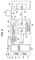
- the internal combustion engine 1 shown in Fig. 1 has a crank mechanism comprising of a connecting rod 4 and a crankshaft 5.
- a combustion chamber 3 is formed with a piston 2 connected to the crank mechanism and an engine head 8 of the engine 1 and hermetically closed by an intake valve 10, an exhaust valve 11, and an ignition plug 12 on the engine head 8.
- the piston 2 is received in a cylinder 1a of the engine 1.
- the intake valve 10 and the exhaust valve 11 are respectively driven by the variable valve mechanisms 40 and 41.
- the engine 1 takes the air required for combustion into the combustion chamber 3 by the operation of the throttle valve 17 and the reciprocal movement of the piston 2.
- the throttle valve 17 is operated in accordance with an electronic throttle valve controlling motor 18.
- the air is filtered clean by an air cleaner 15 before being taken into the combustion chamber 3 and measured by an air flow meter 20. This quantity of the intake air is used for calculation of the quantity of fuel to be injected.
- a pressure sensor 14 in the intake manifold always measures the air pressure in the intake manifold and the result thereof is used to control the engine 1.
- a control unit 63 for controlling the engine 1 is comprised of a running status detecting means 64 for detecting the running status of the engine 1 according to signals from the various sensors, a variable valve controlling means 30 for controlling the variable valve mechanisms 40 and 41 on the engine 1, and a fuel injection controlling means for controlling the quantity of fuel to be injected from the injector 13 and a fuel injection timing.
- the running status detecting means 64 receives other signals from a crank angle sensors which is comprised of components 6 and 7 mounted on the crankshaft 5, from the above stated air flow meter 20, from a pressure sensor 14 in the intake manifold, from an air-fuel ratio sensor 24 provided in the intake manifold, from a temperature sensor 25 for detecting the temperature of the exhaust catalyst 26 in an exhaust port 23, from a pressure sensor 21 which is provided in the combustion chamber 3 and detects a pressure in the combustion chamber 3, and a knocking sensor 22 for detecting knockings.
- a crank angle sensors which is comprised of components 6 and 7 mounted on the crankshaft 5, from the above stated air flow meter 20, from a pressure sensor 14 in the intake manifold, from an air-fuel ratio sensor 24 provided in the intake manifold, from a temperature sensor 25 for detecting the temperature of the exhaust catalyst 26 in an exhaust port 23, from a pressure sensor 21 which is provided in the combustion chamber 3 and detects a pressure in the combustion chamber 3, and a knocking sensor 22 for detecting knockings.
- the variable valve controlling means 30 receives the signals from the running status detecting means 64 and outputs control signals to the variable valve mechanism 40 which drives the intake valve 10 and to the electronically controlled throttle valve drive motor 18 which drives the throttle valve 17 to control the quantity of air taken into the engine 1.
- the fuel injection control means 66 receives the signals from the running status detecting means 64, and outputs a control signal to the fuel injector 13 to control the quantity of fuel to be injected and the fuel injection timing.
- diagnosis apparatus of the internal combustion engine of this embodiment according to the present invention uses rectangular valve lift value shapes of the intake valve 10 and the exhaust valve 11, the similar effect can be obtained by using trapezoidal valve-lift value shapes which can reduce the valve opening/closing operating speeds.
- variable valve mechanism 40 of the engine diagnosis apparatus of the internal combustion engine 1 of this embodiment according to the present invention will be explained in detail referring to Fig. 2.
- the intake valve 10 can move along a valve guide 31 mounted on the engine head 8.
- a stem 10a of the intake valve 10 has a plate 32 which can be attracted by the electromagnetic means 50 and 51 and a member 33 for fixing the plate 32 to the stem 10a of the intake valve.
- the control unit 63 shown in Fig. 1 sends a control signal to the electromagnetic means 50 or 51
- the plate 32 is electromagnetically attracted to the electromagnetic means 50 or 51 to open or close the intake valve 10.
- the control unit 63 feeds a control signal to the electromagnetic means 50 and consequently the plate 32 is attracted to the electromagnetic means 50.
- the valve head 10c of the intake valve 10 goes away from a valve seat on the engine head 8. As the result, an intake port 19 opens to the combustion chamber 3 and lets the air go into the combustion chamber 3. While the intake valve 10 is open, the signal remains fed to the electromagnetic means 51 and the plate 32 remains attracted to the electromagnetic means 51.
- the intake valve 10 retains a preset valve lift close to the maximum valve lift.
- the control unit 63 stops feeding the signal to the electromagnetic means 50 and starts feeding the signal to the electromagnetic means 51.
- the plate 32 is attracted to the electromagnetic means 51.
- the valve head 10c of the intake valve 10 comes in close contact with the valve seat and the intake port 19 is shut away from the combustion chamber 3.
- the air supply to the combustion chamber 3 is complete.
- the intake valve 10 starts to open before the exhaust valve 11 closes at a crank angle of 85 degrees and immediately gets a preset valve lift close to or equal to the maximum valve lift and retains the valve lift for a preset time period.
- the maximum valve lift of the intake valve 10 is greater than that of the exhaust valve 11.
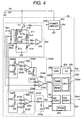
- a sensor circuit 210 connected to a power supply 201 constitutes a sensing part of the thermal air flow meter 20 which heats the heating resistor 211 to keep it at a preset temperature and measures the flow rate of air flowing over the heating resistor 211 from heat loss corresponding to the velocity of the air.
- the error correction unit equipped with a micro-processor 220 receives signals Vin and Vbi from the sensor circuit 210, converts them into digital values by the analog-to-digital converter (A/D converter) 221, corrects the values by the processing circuit 222 according to the correction data stored in a rewritable memory 223, converts the values to have the same voltage values as those of the sensor circuit 210 by the digital-to-analog converter (D/A converter), then outputs the result to the control unit 63 of the engine 1.
- the error correcting unit comprising of the sensor circuit 210, the micro-processor 220 and the power supply circuit 203 which generates a reference voltage constitutes the air flow meter 20.
- the engine control unit 63 receives a signal Vout from the air flow meter 20, converts it into a digital value by the analog-to-digital converter (A/D converter) 631 and uses the result for engine control. At the same time, the engine control unit 63 sends a control signal from the I/O terminal (I/O) 225 to the variable valve controlling means 30 and a variable valve control timing to the I/O terminal (I/O) 225 of the micro-processor 220, which also enables the air flow meter 20 to grasp the operating status of the variable valve mechanism and to trouble diagnose.
- the control signal can be any of a signal which directly controls the valve timing and a control command value which is transferred as pulse like amplitude data.
- the sensor circuit 210 connected to the power supply 201 outputs a signal proportional to an air flow rate.
- the sensor circuit 210 is comprised of a Wheatstone bridge having heating resistors (exothermal resistors or heating conductors) 211a and 211b, a temperature compensating resistor 211c, and resistors 213 and 214, a differential amplifier 215, and a transistor 216.
- the current flowing through the heating resistors 211a and 211b is controlled by the differential amplifier 215 and the transistor 216 so that the potential difference at the center of the bridge may be zero.
- This construction controls to keep the resistances of the resistors 211a and 211b constant in regardless of the largeness of the air flow velocity, namely to keep the resistors 211a and 211b at a preset temperature.
- a signal indicating an air flow rate which is determined by the heating resistors 211a and 211b is fed to a zero-span circuit 2120 which is comprised of a differential amplifier 2121, and resistors 2122, 2123, 2124, 2125, 2126, and 2127.
- a direction detection signal Vbi representing the direction of an air flow is obtained by the heating resistors 211a and 211b, the resistors 212a and 212b of the bridge circuit which are placed in parallel along to the flow of the air and by a direction detection circuit 2130 comprising of differential amplifiers 2131 and 2141 and resistors 2132, 2133, 2134, 2135, 2136, and 2142, 2143, and 2144.
- the above stated heating resistors 211a and 211b are made of a thin or thick heat generating film of a compound of metal such as platinum, nickel, or tungsten or a poly-silicone resistor on a substrate such as a glass, ceramic, or silicone plate.
- a voltage output Vin without a phase difference can be obtained for example by adding a phase delay circuit 2150 comprising of a resistor 2151 and a capacitor 2152.
- This example uses a primary filter as a phase delay circuit, but it is possible to make a phase delay by adding a capacitor in parallel to the resistor 2125 of the zero-span circuit 2120.
- the above stated heating resistors 211a and 211b are provided in the intake manifold of the internal combustion engine 1 of a vehicle or the like and outputs a voltage proportional to the flow rate of air moving or air flowing through the intake air passage in the form of a voltage output Vin of the differential amplifier 2121.
- This output voltage Vin is fed to an analog-to-digital converter 221 built in the micro-processor 220, converted into a digital signal, and operated into an air flow rate by the CPU 222 in the micro-processor 220 according to the output-voltage vs air flow rate formula.
- the result undergoes error corrections and digital-to-analog conversion by the digital-to-analog converter 224, and output as a voltage value to the engine control unit and the like.
- the other components of the micro-processor 220 are a non-volatile memory (ROM) 222c storing flow-rate maps and programs, a rewritable memory (PROM) 223 storing individual difference information such as data of fluctuation of resistances of the heating resistors 211a and 211b, a random access memory (RAM) 222b to be used as a working area of the CPU 222a, an oscillator (OSC) 226 which generates an internal clock, and I/O terminals (I/O) 225.
- ROM non-volatile memory
- PROM rewritable memory
- RAM random access memory
- OSC oscillator
- I/O terminals I/O
- the rewritable memory (PROM) 223 needs not be built in the micro-processor 220. It can be ROM of the fuse type, electrically erasable ROM (EEPROM), a flash memory which can be cleared at once, or fast non-volatile memory using polarization characteristics of ferrodielectric films as far as its storage capacity is enough for one writing.
- EEPROM electrically erasable ROM
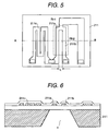
- FIG. 5 shows an example of heating resistors 211a and 211b.
- This example has poly-silicone resistor elements on the flat silicone substrate 211.
- the heating resistors 211a and 211b are placed in parallel with each other on the silicone substrate 211 and a voltage for a bridge circuit is taken in from the mid-point of the resistors 211a and 211b.
- This silicone substrate 211 also has a temperature compensating resistor 211c on it.
- the silicone substrate 211 is etched off to provide a space s under the heating resistors 211a and 211b, which thermally easily insulates the heating resistors 211a and 211b from each other and improves the response to the air flow.
- Fig. 7 shows a temperature distribution of the heating resistors 211a and 211b assuming that the air flows from a direction A to a direction B on the silicone substrate 211. Although the heating resistors 211a and 211b are heated evenly, but the heating resistor 211b in the downstream side of the air flow becomes a little hotter than the heating resistor 211a in the upstream side.
- This temperature difference becomes greater as the distance L between the heating resistors 211a and 211b becomes wider and the sensitivity of the bridge circuit becomes higher.
- this increases a thermal delay as more areas must be heated up.
- This embodiment according to the present invention can obtain an exact flow rate signal proportional to the air flow even when the distance L is wide enough to assure the sensitivity.
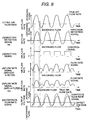
- Fig. 8 shows detailed operating waveforms.
- the true air flow (1) signal is a pulsating waveform containing the backward flow from the engine 1
- the direction detection signal Vbi(2) has a phase difference due to a thermal response delay.
- the direction signal (3) can be obtained by discriminating the direction detection signal Vbi(2) at a preset level Vof.
- the direction detection signal Vbi(2) is basically very low to be sensed, it must be amplified greatly in the direction detection circuit 2130. Consequently, the direction detection signal Vbi(2) is apt to be affected by drifts of the arithmetic amplifier or the like.
- the flow-rate signal (4) has a little delay in response to the direction detection signal Vbi.
- this construction cannot detect the direction of the air flow, the signal for the backward flows is also positive.
- phase delay circuit adjusts the phases to get a phase-matched flow rate signal (5).
- micro-processor 220 internally processes the signal to give a sign to the flow rate signal (5) according to the direction signal. With this, a correct flow-rate signal (6) can be obtained.
- this embodiment according to the present invention is one of means to measure the quantity of a backward flow and a flow direction, its construction is comparatively simple and of a low cost.
- Fig. 9 assumes that a timing Pin1 of the exhaust signal and a timing Pin2 of the intake signal of the variable valve mechanism overlap with each other.
- the valve timing (1) shows the quantity of the valve lift of each of the intake valve 10 and the exhaust valve 11 and the valve timings of each of the intake valve and the exhaust valve.
- the exhaust valve and the intake valve are open at a time for a preset time overlap period according to a timing signal.
- the actual (true) air flow rate (2) contains the backward flow corresponding to this overlap quantity.
- the quantity of this overlap is obtained from the overlap time Ts and the internal EGR quantity Qegr in the intake/exhaust gas.
- the direction signal (4) and the forward/backward flow cycles can be measured by discriminating the backward flow range of the direction detection signal Vbi(3) with a preset level Vof. Further the quantity of backward flow Qbi can be obtained using the forward/backward flow cycles and the flow rate signal Vin.
- Fig. 10 shows a graph showing the relationship between backward flow phases Tbi and overlap time periods Ts as the command values, which are a predicted result of measurement.
- the backward flow phase Tbi becomes greater as the overlap time period Ts increases. However, this is dependent upon a condition which is set as the command value.
- the signal varies according to the speed of the engine 1.
- setting 1 is for slow engine speed
- setting 2 is for middle engine speed
- setting 3 is for high engine speed.
- the relationship between the assumed output values and the command values is stored as reference values as the sensor characteristics under respective setting conditions. The actually detected values are compared by these stored values to judge whether the variable valve mechanism is in the normal operating status.
- Fig. 11 shows a graph showing the relationship between the quantity of backward flow Qbi when the backward flow occurs and the internal EGR quantity Qegr of the intake valve 10 and the exhaust valve 11 which are open at the same time as the command values, which is a predicted result of measurement.
- the quantity of backward flow Qbi becomes greater as the command value Qegr (target EGR quantity) increases. However, this is dependent upon a condition which is set as the command value.
- the signal varies according to the speed of the engine 1.
- setting 1 is for slow engine speed
- setting 2 is for middle engine speed
- setting 3 is for high engine speed.
- the relationship between the assumed output values and the command values is stored as reference values as the sensor characteristics under respective setting conditions. The actually detected values are compared by these stored values to judge whether the variable valve mechanism is in the normal operating status.
- Fig. 12 shows this operation flow for diagnosing the operation only.
- the engine diagnosis apparatus receives command values Ts and Qegr by a valve timing command value (701), gets outputs Vbi and Vin from the sensor signal detector 702, converts the outputs into a flow rate Qa by the air flow rate converter 703 according to the internally defined voltage vs flow rate conversion map, detects the quantity of backward flow Qbi (704) from the direction signal when the backward flow occurs, gets the backward flow phase Tbi from the backward flow phase detector 705, and compares (706) the backward flow phase Tbi by the target map value under the setting condition of the command value Ts.
- the engine diagnosis result "abnormal A” (708) backward flow phase error
- the engine diagnosis apparatus compares the quantity of backward flow Qbi by the target map value under the setting condition of the command value Qegr. If the quantity of backward flow Qbi is smaller than the target map value, the engine diagnosis result "Abnormal B" (708) (backward flow quantity error) is posted.
- the engine diagnosis apparatus ends the diagnosis processing.
- This operation flow enables beautifully diagnoses of the internal combustion engine 1 such as diagnosing for the backward flow phase error only and the detection of no backward flow quantity in the presence of the backward flow phase.
- the engine diagnosis apparatus of the first embodiment according to the present invention using the means for measuring command value signals to control intake/exhaust valve open periods and the flow rate of air flowing through the intake manifold of the engine 1 together with the direction of air flow can facilitate the diagnosis of the operating status of the valve mechanism of the engine diagnosis apparatus.
- the air flow meter 20 which receives the command signal to control the opening time of the exhaust valve or the intake valve enables both measurement of an air flow rate and the diagnosis of the variable valve mechanism. It is possible to forcibly set a low output level or a high output level to indicate an abnormal status of the valve mechanism, but it is possible to provide a communication function to send both the measured air flow rate and the result of diagnosis.
- This engine diagnosis apparatus of this embodiment according to the present invention has merits of enabling diagnosis of the variable valve mechanism without any extra sensor and reducing the load of the engine control unit.
- the air flow meter 20 of this embodiment according to the present invention does not have a function to diagnose the operating status of the variable valve mechanism.
- the sensor circuit connected to a power supply 201 heats a heating resistor 211 to keep it at a preset temperature and measures the flow rate of air flowing over the heating resistor 211 by sensing the quantity of heat deprived from the heating resistor 211.
- This sensor circuit together with the power supply circuit 203 constitutes the air flow meter 20.
- the engine control unit 63 receives a signal Vin from the air flow meter 20, converts it into a digital value by the analog-to-digital converter 631 and uses the result for engine control. At the same time, the engine control unit 63 sends a control signal from the I/O terminal (I/O) 662 to the variable valve controlling means 30 and simultaneously receives a pulse like direction signal Vbs proportional to the flow direction from the air flow meter 20.
- I/O terminal (I/O) 662 to the variable valve controlling means 30 and simultaneously receives a pulse like direction signal Vbs proportional to the flow direction from the air flow meter 20.
- the sensor circuit 210 connected to the power supply 201 outputs a signal proportional to an air flow rate.
- the sensor circuit 210 is comprised of a Wheatstone bridge having heating resistors 211a and 211b, a temperature compensating resistor 211c, and resistors 213 and 214, a differential amplifier 215, and a transistor 216.
- the current flowing through the heating resistors 211a and 211b is controlled by the differential amplifier 215 and the transistor 216 so that the potential difference at the center of the bridge may be zero.
- This construction controls to keep the resistances of the resistors 211a and 211b constant, namely to keep the resistors 211a and 211b at a preset temperature.
- a signal indicating an air flow rate which is determined by the heating resistors 211a and 211b is fed to a zero-span circuit 2120 which is comprised of a differential amplifier 2121, and resistors 2122, 2123, 2124, 2125, 2126, and 2127.
- the zero point and the span can be adjusted for example by the resistance trimming the resistors 2125 and 2126.
- a pulse like direction signal Vbs can be obtained by amplifying a signal from the bridge circuit comprising of resistors 212a and 212b and heating resistors 211a and 211b which are placed in parallel with the flow of the air by the differential amplifier 2131 and resistors 2132, 2134, 2135, 2136, and 2138 and processing the result by a comparator 2145, and resistors 2147, 2148, and 2146.
- the above stated heating resistors 211a and 211b are made of a thin heat generating film or a thick heat generating film of a compound of metal such as platinum, nickel, or tungsten or a poly-silicone resistor on a substrate such as a glass, ceramic, or silicone plate.
- a voltage output Vin without a phase difference can be obtained for example by adding a phase delay circuit 2150 comprising of a resistor 2151 and a capacitor 2152.
- This example uses a primary filter as a phase delay circuit, but it is possible to make a phase delay by adding a capacitor in parallel to the resistor 2125 of the zero-span circuit 2120.
- the above stated heating resistors 211a and 211b are provided in the intake manifold of an internal combustion engine 1 of a vehicle or the like and outputs a voltage proportional to the flow rate of air moving or air flowing through the intake air passage in the form of a voltage output Vin of a differential amplifier 2121.
- This output voltage Vin is fed to an analog-to-digital converter 631 built in the engine control unit 63, converted into a digital signal, and operated into an air flow rate by the CPU 222 in the engine control unit 63 according to the output-voltage vs air flow rate formula. The result is used for various controlling.
- the engine diagnosis apparatus of this embodiment diagnoses the operating status of the variable valve mechanism by using the pulse like direction signal Vbs and the voltage output Vin independent of the air flow.
- the variable valve mechanism can be diagnosed by the engine control unit 63 without any extra diagnosing processor.
- valve timing (1) if one of the cylinders has a valve trouble, the air flow rate or the backward flow range in the actual (true) flow rate (2) may be less than that in the normal valve operation.
- this reduction is represented with a lower peak in the flow rate signal Vin (3) before and after the cylinder that caused the trouble.
- the micro-processor 220 internally compares the peak value of the troubled cylinder by the peak value of each cylinder to judge the difference (the displace amount). Further, the valve trouble can also be detected by a ratio of a forward flow direction range by a backward flow direction range in the direction signal (4) because differences are frequently found before and after the troubled cylinder.
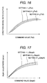
- Fig. 16 shows a graph showing the relationship between the direction signal ratio Tn1/Tn2 and the overlap time Ts2 as the command value, which is a predicted result of measurement.
- the direction signal ratio Tn1/Tn2 becomes greater as the overlap time period Ts increases. Due to the direction signal ratios, the value fluctuation by conditions set as the command values is very little.
- the relationship between the assumed output values and the command values is stored as the reference values as the sensor characteristics under respective setting conditions.
- the actually detected values are compared by these stored values to judge whether the variable valve mechanism is in the normal operating status. It is also possible to use a crank angle signal to specify a troubled cylinder and it is possible to discriminate the trouble cycle.
- Fig. 17 shows a graph showing the relationship between the ratio dn/un of the forward flow peak value and the backward flow peak value and the quantity Qegr2 of the internal EGR in the intake gas and the exhaust gas during the overlap time as the command value.
- the peak value ratio dn/un becomes greater as the command value Qegr increases. Due to the peak value ratios, the value fluctuation by conditions set as the command values is very little.
- Fig. 18 shows this operation flow for diagnosing the operation only.
- the engine diagnosis apparatus receives command values Ts2 and Qegr2 by a valve timing command value 721, gets outputs Vin and Vbs from the sensor signal detector 722, converts the outputs into the flow rate Qa by the air flow rate converter 723 according to the internally defined voltage vs flow rate conversion map, and detects direction signals Tn1 and Tn2 by the direction signal detector 724.
- the engine diagnosis apparatus performs the forward/backward flow detection 725 according to the direction signals and gets the forward flow peak value un and the backward flow peak value dn, and calculates the ratio of detected values un and dn (726) to get a direction signal ratio tnr and a peak value ratio udr.
- the engine diagnosis apparatus compares (727) the direction signal ratio tnr by the target map value under the setting condition of the command value Ts2. If the ratio is smaller than the target value, the diagnosis result "Abnormal A" (729) (backward flow phase error) is posted. When the direction signal ratio tnr is within the target value, the engine diagnosis apparatus compares (728) the peak value ratio udr by the target map value under the setting condition of the command value Qegr2.
- the engine diagnosis apparatus ends the diagnosis processing.
- This operation flow enables extremely diagnoses of the internal combustion engine 1 such as judging for the backward flow phase error only and the discrimination of a composite trouble of respective cylinders.
- the use of ratios can make the measurement more independent of the influence by the engine speeds and reduce the number of target map values under the set condition, for example to one map value.
- the engine control unit 63 can perform judging by a built-in diagnosis software.
- the software contains the variable valve driving timing signals and the valve timing command values, the engine diagnosis apparatus requires no additional wiring and alteration, which makes the system more compatible.
- EGR ways to feed back the exhaust gas into the combustion chamber 3 There are two EGR ways to feed back the exhaust gas into the combustion chamber 3, which are an external EGR way which bypasses the exhaust gas from the engine 1 to the intake manifold and an internal EGR way which keeps part of the exhaust gas in the combustion chamber 3.
- the EGR technology it is very significant to mix up the fed-back exhaust gas with a fresh intake.
- the external EGR technique can mix up the fed-back exhaust gas fully with the fresh intake, but it requires additional bypass conduits and valves to control the quantity of the bypassed exhaust gas, which increases the production cost.
- the internal EGR technique insufficiently mixes the fed-back exhaust gas with the fresh intake and cannot control the quantity of exhaust gas to be left in the combustion chamber 3.
- the exhaust valve 11 starts to open at the crank angle of 75 degrees and lets the exhaust gas go into the exhaust conduit. In this exhaust process, the exhaust valve 11 opens between the crank angle of 95 degrees and the crank angle of 96 degrees to feed the exhaust gas to the intake port 19. The exhaust gas in the intake port 19 is mixed up with the fresh air which is taken in the succeeding intake process.
- This gas mixture (EGR gas) and the fresh air are taken into the combustion chamber 3 when the intake valve 10 opens at the crank angle of 85 degrees.
- the quantity of the EGR gas can be controlled by an intake signal P2 given to the intake valve 10 which opens in the exhaust process.
- the engine diagnosis apparatus of this embodiment according to the present invention employs the internal EGR technology, it requires no additional parts such as bypass conduits and valves, which reduces the production cost. Further, this embodiment with the variable valve mechanism according to the present invention can easily control the quantity of the internal EGR gas.
- the engine diagnosis apparatus and the engine diagnosis method in accordance with the present invention uses signals to drive electromagnetic means built in the variable valve mechanism and the air flow meter which can detect the direction of air flow. With this, the engine diagnosis apparatus and the engine diagnosis method can sequentially diagnose the operating status of the variable valve mechanism of the engine and thus increases the safety of the engine system.
Landscapes
- Engineering & Computer Science (AREA)
- Mechanical Engineering (AREA)
- General Engineering & Computer Science (AREA)
- Chemical & Material Sciences (AREA)
- Combustion & Propulsion (AREA)
- Physics & Mathematics (AREA)
- Electromagnetism (AREA)
- Combined Controls Of Internal Combustion Engines (AREA)
- Output Control And Ontrol Of Special Type Engine (AREA)
- Testing Of Engines (AREA)
Applications Claiming Priority (2)
| Application Number | Priority Date | Filing Date | Title |
|---|---|---|---|
| JP367899 | 1999-01-11 | ||
| JP00367899A JP3799851B2 (ja) | 1999-01-11 | 1999-01-11 | 内燃機関の診断方法 |
Publications (2)
| Publication Number | Publication Date |
|---|---|
| EP1020623A2 true EP1020623A2 (de) | 2000-07-19 |
| EP1020623A3 EP1020623A3 (de) | 2001-01-24 |
Family
ID=11564085
Family Applications (1)
| Application Number | Title | Priority Date | Filing Date |
|---|---|---|---|
| EP00100148A Withdrawn EP1020623A3 (de) | 1999-01-11 | 2000-01-10 | Vorrichtung und Verfahren zur Diagnose einer Brennkraftmaschine |
Country Status (4)
| Country | Link |
|---|---|
| US (1) | US6457353B1 (de) |
| EP (1) | EP1020623A3 (de) |
| JP (1) | JP3799851B2 (de) |
| KR (1) | KR20000053439A (de) |
Cited By (6)
| Publication number | Priority date | Publication date | Assignee | Title |
|---|---|---|---|---|
| FR2816659A1 (fr) * | 2000-11-15 | 2002-05-17 | Sagem | Procede de regulation de la temperature de la masse d'air admise dans un cylindre d'un moteur a combustion interne et moteur mettant en oeuvre ce procede |
| FR2831213A1 (fr) * | 2001-10-19 | 2003-04-25 | Siemens Ag | Procede de surveillance d'un dispositif capteur servant a detecter la course d'une soupape d'admission d'un moteur a combustion interne |
| EP1731746A1 (de) * | 2005-06-07 | 2006-12-13 | Dr.Ing. h.c.F. Porsche Aktiengesellschaft | Verfahren und Vorrichtung zur Überwachung der Funktionstüchtigkeit einer Ventilhub-Verstelleinrichtung einer Brennkraftmaschine in einer Kaltstartphase |
| FR2912457A1 (fr) * | 2007-02-12 | 2008-08-15 | Valeo Sys Controle Moteur Sas | Actionneur electromagnetique de soupape ayant un mode normal et un mode degrade de fonctionnement |
| US7527027B2 (en) | 2004-10-19 | 2009-05-05 | Toyota Jidosha Kabushiki Kaisha | Abnormality determination apparatus for intake amount control mechanism |
| EP1426599A4 (de) * | 2001-09-14 | 2009-05-06 | Honda Motor Co Ltd | Störungsdetektor für fahrzeug mit verzögerungs/leerlauf-zylinder-motor |
Families Citing this family (30)
| Publication number | Priority date | Publication date | Assignee | Title |
|---|---|---|---|---|
| JP2001182596A (ja) * | 1999-12-28 | 2001-07-06 | Mikuni Corp | 内燃機関の吸気圧力検出装置 |
| JP2002106373A (ja) * | 2000-10-02 | 2002-04-10 | Mikuni Corp | 電磁アクチュエータによるエンジン吸気バルブ開閉制御装置 |
| JP4049557B2 (ja) * | 2001-07-26 | 2008-02-20 | 株式会社日立製作所 | 内燃機関のフェールセーフ制御装置 |
| US6595043B2 (en) * | 2001-09-12 | 2003-07-22 | Daimlerchrysler Corporation | Pressure measurement system |
| JP3706335B2 (ja) * | 2001-12-12 | 2005-10-12 | 本田技研工業株式会社 | 内燃機関の故障判定装置 |
| JP2004003404A (ja) * | 2002-06-03 | 2004-01-08 | Hitachi Ltd | 電子制御式絞り弁装置、当該装置等に用いられる非接触式回転角度検出装置、ホール素子の信号処理装置。 |
| US7013211B2 (en) * | 2002-12-02 | 2006-03-14 | Hitachi, Ltd. | Variable valve control apparatus for internal combustion engine and method thereof |
| US6810725B2 (en) * | 2003-02-28 | 2004-11-02 | Cummins Inc. | Exhaust gas recirculation measurement device |
| US6990856B2 (en) * | 2003-06-13 | 2006-01-31 | General Motors Corporation | Method and apparatus for determining mass of engine intake air with reversion compensation |
| DE10330253A1 (de) * | 2003-07-04 | 2005-01-20 | Robert Bosch Gmbh | Sensorelement |
| US7066121B2 (en) * | 2004-03-19 | 2006-06-27 | Ford Global Technologies, Llc | Cylinder and valve mode control for an engine with valves that may be deactivated |
| KR100610106B1 (ko) * | 2004-08-11 | 2006-08-10 | 현대자동차주식회사 | 엔진 시스템의 연료 분사량 결정 방법 |
| US7082934B2 (en) * | 2004-08-24 | 2006-08-01 | Ford Global Technologies, Llc | Controlling spark for an engine with controllable valves |
| DE102004062406B4 (de) | 2004-12-23 | 2007-08-09 | Siemens Ag | Verfahren und Vorrichtung zum Ermitteln einer Phase einer Brennkraftmaschine |
| JP4314585B2 (ja) * | 2006-06-16 | 2009-08-19 | 株式会社デンソー | 内燃機関の制御装置 |
| US7228729B1 (en) | 2006-07-26 | 2007-06-12 | Lincoln Industrial Corporation | Apparatus and method for testing fuel flow |
| JP4483885B2 (ja) * | 2007-03-29 | 2010-06-16 | トヨタ自動車株式会社 | 内燃機関の制御装置 |
| US7587931B2 (en) * | 2008-01-29 | 2009-09-15 | Lincoln Industrial Corporation | Apparatus and method for testing fuel flow |
| DE102008012459B3 (de) * | 2008-03-04 | 2009-09-10 | Continental Automotive Gmbh | Verfahren und Vorrichtung zum Betreiben einer Brennkraftmaschine |
| DE102008014069B4 (de) | 2008-03-13 | 2009-11-26 | Continental Automotive Gmbh | Verfahren und Vorrichtung zum Betreiben einer Brennkraftmaschine |
| WO2009148893A1 (en) * | 2008-06-02 | 2009-12-10 | Borgwarner Inc. | Passive pressure-responsive engine valve unseating |
| US7921709B2 (en) * | 2009-01-13 | 2011-04-12 | Ford Global Technologies, Llc | Variable displacement engine diagnostics |
| ITMI20130835A1 (it) * | 2013-05-22 | 2014-11-23 | Metrel S P A | Attrezzatura modulare, particolarmente per il controllo delle sedi delle valvole ricavate nelle teste dei motori a combustione interna. |
| KR101534712B1 (ko) * | 2013-12-17 | 2015-07-08 | 현대자동차 주식회사 | 연소압 신호에 의한 부스트 압력 센서 및 공기 유량 센서의 진단 및 보정 방법 및 시스템 |
| JP6327339B2 (ja) * | 2014-04-11 | 2018-05-23 | 日産自動車株式会社 | 内燃機関の制御装置および制御方法 |
| US10604147B2 (en) * | 2017-11-06 | 2020-03-31 | Ford Global Technologies, Llc | Systems and methods for diagnosing a vehicle engine intake manifold and exhaust system |
| JP7222363B2 (ja) * | 2020-01-07 | 2023-02-15 | トヨタ自動車株式会社 | エアフロメータの異常診断装置 |
| JP7481080B2 (ja) * | 2020-10-29 | 2024-05-10 | 株式会社奥村組 | 泥水式シールド掘進機 |
| US11434839B2 (en) * | 2020-12-30 | 2022-09-06 | Tula Technology, Inc. | Use of machine learning for detecting cylinder intake and/or exhaust valve faults during operation of an internal combustion engine |
| WO2022150404A1 (en) | 2021-01-11 | 2022-07-14 | Tula Technology Inc. | Exhaust valve failure diagnostics and management |
Citations (4)
| Publication number | Priority date | Publication date | Assignee | Title |
|---|---|---|---|---|
| JPH0491330A (ja) | 1990-08-06 | 1992-03-24 | Nissan Motor Co Ltd | Vtc装置の故障判別装置 |
| JPH06317117A (ja) | 1993-04-28 | 1994-11-15 | Unisia Jecs Corp | 可変バルブタイミング制御装置の自己診断装置 |
| JPH06317115A (ja) | 1993-04-28 | 1994-11-15 | Unisia Jecs Corp | 可変バルブタイミング制御装置の自己診断装置 |
| JPH07293287A (ja) | 1994-04-28 | 1995-11-07 | Unisia Jecs Corp | 内燃機関における可変バルブタイミング制御装置の自己診断装置 |
Family Cites Families (2)
| Publication number | Priority date | Publication date | Assignee | Title |
|---|---|---|---|---|
| US5495830A (en) * | 1995-04-05 | 1996-03-05 | General Motors Corporation | Variable valve timing |
| JP3823510B2 (ja) * | 1998-02-02 | 2006-09-20 | 日産自動車株式会社 | 筒内直噴式内燃機関 |
-
1999
- 1999-01-11 JP JP00367899A patent/JP3799851B2/ja not_active Expired - Lifetime
-
2000
- 2000-01-10 EP EP00100148A patent/EP1020623A3/de not_active Withdrawn
- 2000-01-10 KR KR1020000000916A patent/KR20000053439A/ko not_active Withdrawn
- 2000-01-11 US US09/480,693 patent/US6457353B1/en not_active Expired - Fee Related
Patent Citations (4)
| Publication number | Priority date | Publication date | Assignee | Title |
|---|---|---|---|---|
| JPH0491330A (ja) | 1990-08-06 | 1992-03-24 | Nissan Motor Co Ltd | Vtc装置の故障判別装置 |
| JPH06317117A (ja) | 1993-04-28 | 1994-11-15 | Unisia Jecs Corp | 可変バルブタイミング制御装置の自己診断装置 |
| JPH06317115A (ja) | 1993-04-28 | 1994-11-15 | Unisia Jecs Corp | 可変バルブタイミング制御装置の自己診断装置 |
| JPH07293287A (ja) | 1994-04-28 | 1995-11-07 | Unisia Jecs Corp | 内燃機関における可変バルブタイミング制御装置の自己診断装置 |
Cited By (10)
| Publication number | Priority date | Publication date | Assignee | Title |
|---|---|---|---|---|
| FR2816659A1 (fr) * | 2000-11-15 | 2002-05-17 | Sagem | Procede de regulation de la temperature de la masse d'air admise dans un cylindre d'un moteur a combustion interne et moteur mettant en oeuvre ce procede |
| WO2002040853A1 (fr) * | 2000-11-15 | 2002-05-23 | Johnson Controls Automotive Electronics | Procede de regulation de la temperature de la masse d'air admise dans un cylindre d'un moteur a combustion interne et moteur mettant en oeuvre ce procede |
| EP1426599A4 (de) * | 2001-09-14 | 2009-05-06 | Honda Motor Co Ltd | Störungsdetektor für fahrzeug mit verzögerungs/leerlauf-zylinder-motor |
| FR2831213A1 (fr) * | 2001-10-19 | 2003-04-25 | Siemens Ag | Procede de surveillance d'un dispositif capteur servant a detecter la course d'une soupape d'admission d'un moteur a combustion interne |
| US7527027B2 (en) | 2004-10-19 | 2009-05-05 | Toyota Jidosha Kabushiki Kaisha | Abnormality determination apparatus for intake amount control mechanism |
| US8024109B2 (en) | 2004-10-19 | 2011-09-20 | Toyota Jidosha Kabushiki Kaisha | Abnormality determination apparatus for intake amount control mechanism |
| DE102005049853B4 (de) * | 2004-10-19 | 2015-08-20 | Toyota Jidosha Kabushiki Kaisha | Abnormalitätsbestimmungsvorrichtung für einen Ansaugmengensteuerungsmechanismus |
| EP1731746A1 (de) * | 2005-06-07 | 2006-12-13 | Dr.Ing. h.c.F. Porsche Aktiengesellschaft | Verfahren und Vorrichtung zur Überwachung der Funktionstüchtigkeit einer Ventilhub-Verstelleinrichtung einer Brennkraftmaschine in einer Kaltstartphase |
| US7269501B2 (en) | 2005-06-07 | 2007-09-11 | Dr. Ing. H.C.F. Porsche Aktiengesellscaft | Method and device for monitoring the functioning of a valve stroke adjusting device of an internal combustion engine during cold starts |
| FR2912457A1 (fr) * | 2007-02-12 | 2008-08-15 | Valeo Sys Controle Moteur Sas | Actionneur electromagnetique de soupape ayant un mode normal et un mode degrade de fonctionnement |
Also Published As
| Publication number | Publication date |
|---|---|
| US6457353B1 (en) | 2002-10-01 |
| JP3799851B2 (ja) | 2006-07-19 |
| KR20000053439A (ko) | 2000-08-25 |
| JP2000204986A (ja) | 2000-07-25 |
| EP1020623A3 (de) | 2001-01-24 |
Similar Documents
| Publication | Publication Date | Title |
|---|---|---|
| US6457353B1 (en) | Apparatus of diagnosing an internal combustion engine and a method of diagnosing of an internal combustion engine | |
| EP1024272A1 (de) | Steuerungsverfahren für einen turboaufgeladenen Dieselmotor mit Abgasrückführung | |
| US4889098A (en) | Air-fuel ratio detecting apparatus for an internal combustion engine equipped with a heater controller | |
| US6615812B2 (en) | Method and arrangement for operating an internal combustion engine | |
| US6076502A (en) | Exhaust gas recirculation control system for internal combustion engines | |
| JP2586205B2 (ja) | 排気ガス還流制御装置の故障診断装置 | |
| US6009862A (en) | Exhaust gas recirculation control system and method | |
| JPH04507290A (ja) | 熱薄膜式空気重量測定器の測定誤差補正方法 | |
| US7287525B2 (en) | Method of feedforward controlling a multi-cylinder internal combustion engine and associated feedforward fuel injection control system | |
| JP2008069690A (ja) | 排ガス還流制御装置 | |
| US4787966A (en) | Oxygen concentration sensor for an internal combustion engine | |
| JPH0819880B2 (ja) | 排気ガス再循環制御装置 | |
| JP2600807B2 (ja) | 内燃機関の制御装置 | |
| JP3575350B2 (ja) | 空気過剰率設定装置 | |
| JPH07310585A (ja) | 筒内圧センサの診断装置 | |
| JP2001153702A (ja) | 発熱抵抗体式空気流量測定装置の計測誤差補正方法 | |
| JPS63134845A (ja) | 排気ガス再循環制御装置 | |
| JP2847454B2 (ja) | 内燃機関における空燃比検出装置 | |
| JPH10339191A (ja) | エンジンの吸気制御装置 | |
| JPH0531739B2 (de) | ||
| JP3627462B2 (ja) | 内燃機関の制御装置 | |
| JP3551706B2 (ja) | エンジンの吸気制御装置 | |
| JPH01265122A (ja) | 内燃機関の吸入空気量測定装置 | |
| JPH02245444A (ja) | 内燃機関の故障診断装置 | |
| JPH066216Y2 (ja) | 内燃機関におけるアルコールセンサ故障診断装置 |
Legal Events
| Date | Code | Title | Description |
|---|---|---|---|
| PUAI | Public reference made under article 153(3) epc to a published international application that has entered the european phase |
Free format text: ORIGINAL CODE: 0009012 |
|
| AK | Designated contracting states |
Kind code of ref document: A2 Designated state(s): DE FR GB |
|
| AX | Request for extension of the european patent |
Free format text: AL;LT;LV;MK;RO;SI |
|
| PUAL | Search report despatched |
Free format text: ORIGINAL CODE: 0009013 |
|
| AK | Designated contracting states |
Kind code of ref document: A3 Designated state(s): AT BE CH CY DE DK ES FI FR GB GR IE IT LI LU MC NL PT SE |
|
| AX | Request for extension of the european patent |
Free format text: AL;LT;LV;MK;RO;SI |
|
| 17P | Request for examination filed |
Effective date: 20010518 |
|
| AKX | Designation fees paid |
Free format text: DE FR GB |
|
| 17Q | First examination report despatched |
Effective date: 20040429 |
|
| STAA | Information on the status of an ep patent application or granted ep patent |
Free format text: STATUS: THE APPLICATION HAS BEEN WITHDRAWN |
|
| 18W | Application withdrawn |
Effective date: 20040909 |