EP1020711B1 - Durchflussmessgerät für fluide Medien - Google Patents
Durchflussmessgerät für fluide Medien Download PDFInfo
- Publication number
- EP1020711B1 EP1020711B1 EP19990100712 EP99100712A EP1020711B1 EP 1020711 B1 EP1020711 B1 EP 1020711B1 EP 19990100712 EP19990100712 EP 19990100712 EP 99100712 A EP99100712 A EP 99100712A EP 1020711 B1 EP1020711 B1 EP 1020711B1
- Authority
- EP
- European Patent Office
- Prior art keywords
- capsule
- housing
- measuring
- holder
- cable
- Prior art date
- Legal status (The legal status is an assumption and is not a legal conclusion. Google has not performed a legal analysis and makes no representation as to the accuracy of the status listed.)
- Expired - Lifetime
Links
Images

Classifications
-
- G—PHYSICS
- G01—MEASURING; TESTING
- G01F—MEASURING VOLUME, VOLUME FLOW, MASS FLOW OR LIQUID LEVEL; METERING BY VOLUME
- G01F1/00—Measuring the volume flow or mass flow of fluid or fluent solid material wherein the fluid passes through a meter in a continuous flow
- G01F1/66—Measuring the volume flow or mass flow of fluid or fluent solid material wherein the fluid passes through a meter in a continuous flow by measuring frequency, phase shift or propagation time of electromagnetic or other waves, e.g. using ultrasonic flowmeters
- G01F1/662—Constructional details
Definitions
- the propagation speed of certain waves, in particular Sound waves in a fluid medium is dependent of its relative speed.
- This phenomenon uses one in ultrasonic measuring devices for flow measurement.
- the device contains a measuring section through which the medium flows; opposite ends of corresponding sensors or Recipients are provided.
- the measuring section may be considered be very short on the accuracy to be achieved. extends they are in the longitudinal direction between the inlet and outlet connections of the measuring device (EP-A-392 294), one arrives at one large overall length, you move the measuring section outside the the connecting flight (EP-B-88 235). This is also true then, when the measuring section is within this escape is arranged transversely thereto (EP-A-681 162).
- a calibration is therefore only complete Installation of the device possible.
- the measuring accuracy can by changing the position of the encoder and receiver relative to the housing and the position of the housing parts and the measuring tube to each other be affected. The connection of all of these Parts with each other therefore need to be secured and sealed.
- the invention has for its object a flow meter in the preamble of claim 1 (corresponding to US-A-4 140 012) mentioned to create the short and simple Construction combined with easy handling.
- the measuring tube, the distribution chambers and the side channels then form parts of a capsule separate from the housing and mountable as a unit.
- the measuring sensor for example an impeller
- a counter for example a capsule which can be used as a unit in the device housing.
- this idea could not be easily transferred to ultrasonic meters, because the sensors or receivers located on opposite sides are separated from one another by housing parts, namely channels, distribution chambers, and possibly the measuring tube, and are therefore not easily combined to form a unit can be.
- the invention is not limited to the fact that the housing is short and simple and without the sensitive Measurement components can be installed, handling is simple is easy because when maintenance or changing the measuring range the capsule can be replaced and it in many Cases will be possible, the calibration only at the Provide capsule.
- the sensors or receivers provided on the opposite ends of the capsule will often be supplied with cables, for example for energy supply or for signal dissipation. Since the cables outside the device are sensitive to damage, efforts are being made to reduce the number of cable entries into the device and to reduce the exposed cable runs.
- the invention achieves this aim in that the capsule center piece, which forms the channels, includes medium-free spaces with the capsule receptacle outside the cooperating with the capsule receptacle, separately and completely sealed openings, through which the cables at least one cable-supplied end piece of the capsule to the other side of the capsule are led where they can be led out of the device together with the cables of the other capsule end piece.
- the cables of both capsule end pieces can also be routed through these rooms to a cable outlet point located at a third position. In any case, these spaces or spaces connected to these spaces within the center piece of the capsule serve for the protected and dry routing of cables.
- the capsule holder is advantageously open on both sides, so that they have two opposing openings having. At least one of these openings becomes the capsule generally stand out. With a symmetrical arrangement, which generally has advantages, it can be used with either of them Stick ends out of the openings.
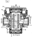
- the housing 1 comprises an inlet connection 2 and an outlet nozzle 3 on opposite sides of the housing are arranged in alignment. You can also - as is known - on the same side of the housing side by side or inside each other Arrange. These and other alternative designs of the housing should be covered by the inventive concept his.
- the sockets show connection threads 4 for connection with subsequent pipes. It understands themselves that the nozzle is also formed in a different way could be. For example, they can each be a final organ included, which serves the respective line branch shut off in order to mount or replace the measuring capsule to enable.
- the housing 1 forms a receptacle between the connecting pieces 2, 3 for the capsule 7.
- the capsule fits one receiving bore 8 with means for holding the capsule is formed in this hole.
- These facilities are in the example shown on the one hand by a retaining ring 9, the thread, bayonet or the like with a collar 10 of the intake cooperates, and the taper of the bore 8 formed.
- the axis 11 of the bore 8 intersects at right angles with the Axis 12 of the nozzle bores 13, 14. These therefore open at opposite positions of the bore 8.
- the capsule 7 consists of a middle piece 20, a lower one End piece 21 with a lower cover 22 and an upper end piece 23 with upper lid 24.
- the middle piece 20 contains openings 25, 26, which connect directly to the nozzle openings 13, 14, when the capsule is inserted in the receptacle and is suitable for the hole at least in the area of the openings 8 trained so that they are safe and in a certain position is held in the bore 8.
- the with regard to the Axial alignment of the openings desired orientation of the Capsule is formed by interlocking projections 28 and depressions 29 on the center piece or the capsule holder ensured.
- the interacting pairs of openings 13, 25 and 14, 26 are each surrounded by a sealing ring, which closes the opening connection completely tight.
- the capsule openings 25, 26 have an annular space 30, 31 in connection, which encloses the measuring tube 32, which by a Diagonal wall 33 is held within the capsule, the Diagonal wall on the one hand with the inlet opening 25 and on the other hand parts 30 connected to the outlet opening 26 or 31 of the annular space.
- These parts 30, 31 of the annulus form the so-called side channels.
- the side channels lead in the illustrated embodiment from the ends of the center piece to the center and are of equal length. It doesn't have to be that way.
- the side channels are of different lengths. One of they can be shortened to zero.
- the ends of the measuring tube 32 end at a distance from the front ends of the middle piece, so that there distribution chambers 34, 35 arise.
- the Flow path of the medium therefore leads from the bore 13 of the Inlet nozzle through the inlet opening 25 of the capsule in the Annulus part 30, through the lower distribution chamber 34 and Measuring section 36 to the distribution space 35 and through the annular space part 31 and the outlet-side opening 26 of the capsule in the Bore 14 of the outlet nozzle.
- the arrangement is symmetrical, since the axis 11 of the capsule and the recording the common axis 12 of the nozzle holes cuts at right angles. However, this is not absolutely necessary.
- axis 11 could be axis 12 be a little inclined or offset to the side.
- the nozzles 2, 3 are not arranged opposite one another the formation of the flow channels within the capsule nevertheless correspond to the illustrated embodiment, if the necessary flow diversions are provided in the housing are.
- the channel arrangement inside the capsule itself deviates from that To design representation, and preferably so that in the measuring section the most suitable for the measuring purposes Flow results. For example, to influence the Flow baffles are housed within the channels as at 37 in the inlet opening 25 of the capsule are indicated.
- the end pieces 21, 23 contain unspecified components for generating or recording a measurement signal and are through a membrane and sealing rings 49 opposite the front ends of the middle piece 20 sealed.
- Your lids 22, 24 are by snap connections indicated at 44 with the center piece connected so that the capsule is handled as a unit can be.
- the covers are secured in the installation position in that by means of a collar 45 behind one corresponding collar 46 of the receptacle or retaining ring 9 to grab. Not only the seat of the middle piece in the recording, but also the capsule caps are covered by the Retaining ring 9 secured. Only this one therefore needs to be sealed to become.
- the retaining ring 9 is a by means of a connecting ring 50 another lid 51 placed, if desired the Cable entry 52 to capsule 7 covers and also other cable guides may contain.
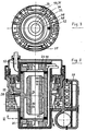
- Fig. 2 shows that to the housing 1, if desired, a counter 53 or the like can be applied.
- the further embodiment according to FIG. 4 has a housing 60 and a capsule 61 inserted therein. Not shown Inlet and outlet of the housing and the corresponding The openings of the capsule are interconnected as explained with reference to FIGS. 1 to 3 has been.
- the capsule 61 contains an impeller 62 as Measuring element, the movement of which by a transmitter / receiver pair 63, 64 is scanned, which is arranged on both sides of the impeller are. It is the passage of the wing through the measuring section 65 found.
- the cables 66 from the lower transmitter or receiver 64 are through those spaces between the capsule 61 and the receptacle formed in the housing 60 to the side of the other donor or recipient 63, which thanks to the Seals enclosing flow connections are free of medium are. Additional components can be found in the upper part 67 of the capsule for forwarding and / or displaying the measurement signal and for Cable entry can be provided.
- Claim 5 a possibly independent of the other claims Protection deserves.
Landscapes
- Physics & Mathematics (AREA)
- Electromagnetism (AREA)
- Fluid Mechanics (AREA)
- General Physics & Mathematics (AREA)
- Measuring Volume Flow (AREA)
Description
- Fig. 1
- einen Schnitt längs durch das Gehäuse und die Kapsel;
- Fig. 2
- einen Schnitt quer zum Gehäuse und längs zur Kapsel;
- Fig. 3
- eine Schnittansicht der Kapsel gemäß Linie III-III der Fig. 2; und
- Fig. 4
- einen Schnitt durch eine weitere Ausführungsform.
Claims (5)
- Durchflußmeßgerät für fluide Medien mit einem einen Zulaufanschluß (2) und einen Auslaufanschluß (3) aufweisenden Gehäuse, das eine Meßstrecke (36) mit einem Meßrohr (32) enthält, das zwei Verteilkammern (34, 35) verbindet, die jeweils mit einem der beiden Anschlüsse (2, 3) über im wesentlichen neben dem Meßrohr (32) gelegene Seitenkanäle (30, 31) verbunden sind, dadurch gekennzeichnet, daß das Meßrohr (32), die Verteilkammern (34, 35) und die Seitenkanäle (30, 31) Teil einer von dem Gehäuse (1) gesonderten und als Einheit in eine im Gehäuse (1) vorgesehene Kapselaufnahme einsetzbaren Kapsel (7) sind, daß die Seitenkanäle (30, 31) mit den Anschlüssen (2, 3) über an der Kapsel (7) und in der Kapselaufnahme angeordnete Öffnungspaare (13, 25 bzw. 26, 14) verbunden sind, daß die Kabel (66) zu einer Seite der Kapsel (7) abgeführt sind und daß die Kapsel (7, 61) an ihrem fern der Kabelabführungsseite des Geräts bzw. der Kapsel liegenden Ende einen kabelversorgten Geber/Empfänger (21, 64) aufweist und die Kapsel außerhalb der mit der Kapselaufnahme dicht zusammenwirkenden Öffnungspaare (13, 25 bzw. 26, 12) mediumsfreie Räume der Kapselaufnahme einschließt und die Kabel des kabelversorgten Gebers/Empfängers (21, 64) durch diese Räume oder damit innerhalb der Kapsel verbundene Räume zur Kabelabführungsseite verlaufen.
- Durchflußmeßgerät nach Anspruch 1, dadurch gekennzeichnet, daß die Kapselaufnahme beiderseits offen ist und die Kapsel (7) daraus mit mindestens einem ihrer Enden herausragt.
- Durchflußmeßgerät nach Anspruch 1 oder 2, dadurch gekennzeichnet, daß die Kapsel mindestens einen Deckel (22, 24) aufweist, der durch Zusammenwirken mit am Gehäuse (1) vorgesehenen Haltemitteln (45, 46) gegen inneren Überdruck gesichert ist.
- Durchflußmeßgerät nach Anspruch 3, dadurch gekennzeichnet, daß die Deckel (22, 24) durch dieselben plombierbaren Mittel (9, 10) an der Kapsel (7) gesichert ist, die die Kapsel (7) in der Aufnahme sichern.
- Durchflußmeßgerät nach einem der Ansprüche 1 bis 3, dadurch gekennzeichnet, daß die Meßstrecke quer zur Richtung des Zulauf- und/oder Auslaufanschlusses (2, 3) angeordnet ist.
Priority Applications (2)
| Application Number | Priority Date | Filing Date | Title |
|---|---|---|---|
| EP19990100712 EP1020711B1 (de) | 1999-01-15 | 1999-01-15 | Durchflussmessgerät für fluide Medien |
| DE59904940T DE59904940D1 (de) | 1999-01-15 | 1999-01-15 | Durchflussmessgerät für fluide Medien |
Applications Claiming Priority (1)
| Application Number | Priority Date | Filing Date | Title |
|---|---|---|---|
| EP19990100712 EP1020711B1 (de) | 1999-01-15 | 1999-01-15 | Durchflussmessgerät für fluide Medien |
Publications (2)
| Publication Number | Publication Date |
|---|---|
| EP1020711A1 EP1020711A1 (de) | 2000-07-19 |
| EP1020711B1 true EP1020711B1 (de) | 2003-04-09 |
Family
ID=8237355
Family Applications (1)
| Application Number | Title | Priority Date | Filing Date |
|---|---|---|---|
| EP19990100712 Expired - Lifetime EP1020711B1 (de) | 1999-01-15 | 1999-01-15 | Durchflussmessgerät für fluide Medien |
Country Status (2)
| Country | Link |
|---|---|
| EP (1) | EP1020711B1 (de) |
| DE (1) | DE59904940D1 (de) |
Cited By (1)
| Publication number | Priority date | Publication date | Assignee | Title |
|---|---|---|---|---|
| CN102162745A (zh) * | 2010-02-16 | 2011-08-24 | 伊特伦法国公司 | 具有标准盒式超声波测量单元的测量计 |
Families Citing this family (8)
| Publication number | Priority date | Publication date | Assignee | Title |
|---|---|---|---|---|
| DE10103745C2 (de) * | 2001-01-26 | 2003-04-17 | Hydrometer Gmbh | Ultraschallzähler mit einer austauschbaren Meßstrecke mit zentraler Fühleranbringung |
| DE10119342C2 (de) * | 2001-04-20 | 2003-07-31 | Hydrometer Gmbh | Flüssigkeitszähler |
| DE102005001897C5 (de) * | 2005-01-14 | 2013-01-17 | Landis+Gyr Gmbh | Ultraschallmessanordnung für den Einbau an einem Einrohranschlussstück in einer Rohrleitung |
| DE102005062629B4 (de) * | 2005-12-23 | 2008-01-24 | Hydrometer Gmbh | Durchflussmesser |
| EP1909076B1 (de) * | 2006-10-04 | 2011-05-18 | Hans-Holger Körner | Durchflussmesser für fluide Medien |
| DE202008002816U1 (de) * | 2008-02-29 | 2009-04-16 | Junker, Raul | Vorrichtung zur Durchflussmessung |
| DE202009004358U1 (de) | 2008-03-28 | 2009-08-20 | Körner, Hans-Holger | Durchflussmessgerät mit exzentrischem Messrohr |
| DE202009016421U1 (de) * | 2009-12-04 | 2011-04-14 | Körner, Hans-Holger | Messkapsel zur Durchflussmessung |
Family Cites Families (5)
| Publication number | Priority date | Publication date | Assignee | Title |
|---|---|---|---|---|
| US4140012A (en) * | 1977-11-07 | 1979-02-20 | Envirotech Corporation | Small pipe flowmeter |
| DE3518266A1 (de) * | 1985-05-21 | 1986-11-27 | Siemens AG, 1000 Berlin und 8000 München | Stroemungsmesser |
| US5463906A (en) * | 1994-01-24 | 1995-11-07 | Triton Technology, Inc. | Interchangeable disposable acoustic for use with an ultrasonic flowmeter, particularly during extracorporeal measurement of blood flow |
| ATE157446T1 (de) * | 1994-05-09 | 1997-09-15 | Koerner Hans Holger | Zähler für flüssigkeiten und gase |
| DE19729473A1 (de) * | 1997-07-10 | 1999-02-04 | Meinecke Ag H | Ultraschall-Durchflußmesser |
-
1999
- 1999-01-15 DE DE59904940T patent/DE59904940D1/de not_active Expired - Lifetime
- 1999-01-15 EP EP19990100712 patent/EP1020711B1/de not_active Expired - Lifetime
Cited By (1)
| Publication number | Priority date | Publication date | Assignee | Title |
|---|---|---|---|---|
| CN102162745A (zh) * | 2010-02-16 | 2011-08-24 | 伊特伦法国公司 | 具有标准盒式超声波测量单元的测量计 |
Also Published As
| Publication number | Publication date |
|---|---|
| DE59904940D1 (de) | 2003-05-15 |
| EP1020711A1 (de) | 2000-07-19 |
Similar Documents
| Publication | Publication Date | Title |
|---|---|---|
| EP1020711B1 (de) | Durchflussmessgerät für fluide Medien | |
| DE102008049891B4 (de) | Strömungsrichter für ein Durchflussmessgerät, insbesondere ein Ultraschallmessgerät | |
| EP3314214B1 (de) | Durchflusszähler mit messkanal und nebenkanälen | |
| WO2018011372A1 (de) | Durchflussmesser mit messkanal | |
| EP0890826A1 (de) | Ultraschall-Durchflussmesser | |
| DE2458901A1 (de) | Stroemungsmesser | |
| EP2283262B1 (de) | Mehrwegeventil eines brennstoffsystems einer gasturbine | |
| EP0559938B1 (de) | Durchflussmesseinrichtung für flüssige Medien nach dem Ultraschall-Laufzeitprinzip | |
| EP1227303B1 (de) | Ultraschalldurchflusszähler mit einer austauschbaren Messstrecke | |
| EP0392294A1 (de) | Durchflussmesseinrichtung für flüssige Medien nach dem Ultraschall-Laufzeitprizip | |
| EP2988103B1 (de) | Durchflussmesser mit einem in ein gehäuse eingesetzten messeinsatz | |
| EP1978337B1 (de) | Ultraschallzähler zur Bestimmung der Durchflussmenge eines strömenden Mediums | |
| DE7631936U1 (de) | Graet zur messung der luftgeschwindigkeit | |
| EP1909076B1 (de) | Durchflussmesser für fluide Medien | |
| DE4440683A1 (de) | Meßeinsatz für Flüssigkeitszähler | |
| EP4511619B1 (de) | Messvorrichtung und verfahren zu deren herstellung | |
| EP2239544B1 (de) | Messkapsel für Flüssigkeitszähler und Flüssigkeitszähler | |
| DE19731173A1 (de) | Ultraschall-Durchflußmengenmesser | |
| DE10233307B4 (de) | Massendurchflußmeßgerät | |
| DE202009004358U1 (de) | Durchflussmessgerät mit exzentrischem Messrohr | |
| DE102005062629B4 (de) | Durchflussmesser | |
| DE102008032309A1 (de) | Sensoranordnung zur Messung des Zustands einer Flüssigkeit, insbesondere von Öl | |
| DE102004053860B4 (de) | Ultraschallzähler zur Bestimmung der Durchflussmenge eines strömenden Mediums | |
| DE4028780C2 (de) | Strömungsanzeige- oder Strömungsmeßgerät | |
| EP4575420A1 (de) | Durchflussmengenmesser |
Legal Events
| Date | Code | Title | Description |
|---|---|---|---|
| PUAI | Public reference made under article 153(3) epc to a published international application that has entered the european phase |
Free format text: ORIGINAL CODE: 0009012 |
|
| AK | Designated contracting states |
Kind code of ref document: A1 Designated state(s): DE DK FR GB IT |
|
| AX | Request for extension of the european patent |
Free format text: AL;LT;LV;MK;RO;SI |
|
| 17P | Request for examination filed |
Effective date: 20010117 |
|
| AKX | Designation fees paid |
Free format text: DE DK FR GB IT |
|
| GRAH | Despatch of communication of intention to grant a patent |
Free format text: ORIGINAL CODE: EPIDOS IGRA |
|
| GRAH | Despatch of communication of intention to grant a patent |
Free format text: ORIGINAL CODE: EPIDOS IGRA |
|
| GRAA | (expected) grant |
Free format text: ORIGINAL CODE: 0009210 |
|
| AK | Designated contracting states |
Designated state(s): DE DK FR GB IT |
|
| PG25 | Lapsed in a contracting state [announced via postgrant information from national office to epo] |
Ref country code: IT Free format text: LAPSE BECAUSE OF FAILURE TO SUBMIT A TRANSLATION OF THE DESCRIPTION OR TO PAY THE FEE WITHIN THE PRESCRIBED TIME-LIMIT;WARNING: LAPSES OF ITALIAN PATENTS WITH EFFECTIVE DATE BEFORE 2007 MAY HAVE OCCURRED AT ANY TIME BEFORE 2007. THE CORRECT EFFECTIVE DATE MAY BE DIFFERENT FROM THE ONE RECORDED. Effective date: 20030409 Ref country code: GB Free format text: LAPSE BECAUSE OF FAILURE TO SUBMIT A TRANSLATION OF THE DESCRIPTION OR TO PAY THE FEE WITHIN THE PRESCRIBED TIME-LIMIT Effective date: 20030409 Ref country code: FR Free format text: LAPSE BECAUSE OF FAILURE TO SUBMIT A TRANSLATION OF THE DESCRIPTION OR TO PAY THE FEE WITHIN THE PRESCRIBED TIME-LIMIT Effective date: 20030409 |
|
| REG | Reference to a national code |
Ref country code: GB Ref legal event code: FG4D Free format text: NOT ENGLISH |
|
| PG25 | Lapsed in a contracting state [announced via postgrant information from national office to epo] |
Ref country code: DK Free format text: LAPSE BECAUSE OF FAILURE TO SUBMIT A TRANSLATION OF THE DESCRIPTION OR TO PAY THE FEE WITHIN THE PRESCRIBED TIME-LIMIT Effective date: 20030709 |
|
| GBV | Gb: ep patent (uk) treated as always having been void in accordance with gb section 77(7)/1977 [no translation filed] |
Effective date: 20030409 |
|
| PLBE | No opposition filed within time limit |
Free format text: ORIGINAL CODE: 0009261 |
|
| STAA | Information on the status of an ep patent application or granted ep patent |
Free format text: STATUS: NO OPPOSITION FILED WITHIN TIME LIMIT |
|
| EN | Fr: translation not filed | ||
| 26N | No opposition filed |
Effective date: 20040112 |
|
| PGFP | Annual fee paid to national office [announced via postgrant information from national office to epo] |
Ref country code: DE Payment date: 20120321 Year of fee payment: 14 |
|
| PG25 | Lapsed in a contracting state [announced via postgrant information from national office to epo] |
Ref country code: DE Free format text: LAPSE BECAUSE OF NON-PAYMENT OF DUE FEES Effective date: 20130801 |
|
| REG | Reference to a national code |
Ref country code: DE Ref legal event code: R119 Ref document number: 59904940 Country of ref document: DE Effective date: 20130801 |