EP1020737A2 - Procédé et disposif por la détection électromagnétique des objets - Google Patents
Procédé et disposif por la détection électromagnétique des objets Download PDFInfo
- Publication number
- EP1020737A2 EP1020737A2 EP99124408A EP99124408A EP1020737A2 EP 1020737 A2 EP1020737 A2 EP 1020737A2 EP 99124408 A EP99124408 A EP 99124408A EP 99124408 A EP99124408 A EP 99124408A EP 1020737 A2 EP1020737 A2 EP 1020737A2
- Authority
- EP
- European Patent Office
- Prior art keywords
- signal
- display signal
- frequency
- intensity
- acoustic
- Prior art date
- Legal status (The legal status is an assumption and is not a legal conclusion. Google has not performed a legal analysis and makes no representation as to the accuracy of the status listed.)
- Granted
Links
Images


Classifications
-
- G—PHYSICS
- G01—MEASURING; TESTING
- G01V—GEOPHYSICS; GRAVITATIONAL MEASUREMENTS; DETECTING MASSES OR OBJECTS; TAGS
- G01V1/00—Seismology; Seismic or acoustic prospecting or detecting
- G01V1/001—Acoustic presence detection
-
- G—PHYSICS
- G01—MEASURING; TESTING
- G01V—GEOPHYSICS; GRAVITATIONAL MEASUREMENTS; DETECTING MASSES OR OBJECTS; TAGS
- G01V3/00—Electric or magnetic prospecting or detecting; Measuring magnetic field characteristics of the earth, e.g. declination, deviation
- G01V3/08—Electric or magnetic prospecting or detecting; Measuring magnetic field characteristics of the earth, e.g. declination, deviation operating with magnetic or electric fields produced or modified by objects or geological structures or by detecting devices
- G01V3/10—Electric or magnetic prospecting or detecting; Measuring magnetic field characteristics of the earth, e.g. declination, deviation operating with magnetic or electric fields produced or modified by objects or geological structures or by detecting devices using induction coils
Definitions
- the invention relates to a method for electromagnetic Detection of objects with a detector in which Individual pulses are emitted that are to be detected Excite the object to radiate secondary signals that Secondary signals are received, the decay behavior of the Secondary signals are evaluated and one of the intentions and the decay behavior of the secondary signals Display signal is output.
- the invention further relates to a device for electromagnetic Detection of objects with a detector, with a pulse generator, a transmitter for broadcasting of single pulses, a receiving device for receiving of secondary signals and a sample and hold device for generating sampling signals of the secondary signals.
- a generic method and a generic method Devices are known from DE 195 06 339 C2. After that on the one hand by sending out individual impulses, the subsequent reception of secondary pulses of one to be detected Object and determining one by the intensity of the secondary signal dependent size of the principal Provided proof of the existence of an object; the amount of this detected intensity signal is also a measure of the object size and / or the distance of the object to the detector.
- the generic Device the temporal behavior of the secondary signal detected. This is because the decay behavior of the secondary signal is object-dependent. In particular the decay behavior depends on the material of the object from. Recording the decay behavior thus offers the possibility of object or material identification.
- the generic method and the corresponding device particularly good for differentiation between ferromagnetic and non-ferromagnetic Objects.
- the intensity-dependent signal as well as that Cooldown characterizing signals are in the generic Device supplied to display devices, which the signals on the one hand optically and on the other hand from each other display independently.
- DE 42 12 363 C2 describes a metal detector, at which the optical display device of the object identification serves while the actual object detection, i.e. proof that there is an object at all, is conveyed via an acoustic display. Indeed the user is still with the mentioned metal detector before relying on visual observation of a display signal; the metal detector mentioned also makes use of of a fundamentally different detection principle: in Contrast to the generic device and the corresponding Process is not a pulse process (PI circuit), but uses a so-called sine method.
- PI circuit pulse process
- the invention has for its object to improve the generic method and the generic device and in particular to convey the display signal in a convenient manner and to make it easy to interpret and informative.
- the invention builds on the generic method in that an acoustic display signal is used, that a first acoustic characteristic of the display signal depends on the intensity of the secondary signals and that a second acoustic characteristic of the display signal depends on the decay behavior of the secondary signals.
- a particular advantage of this method is that the display signal can only be conveyed on an acoustic basis. This means that the user can use the method under practically any circumstances, especially in poor lighting conditions or even under water.
- the measure that two different acoustic characteristics - or in other words: acoustic variation possibilities - are conveyed to the display signal offers the advantage that in addition to the mere object detection, ie the proof that an object is present at all, an identification of the object properties, ie in particular a distinction between ferromagnetic and non-ferromagnetic objects can be realized. Since the two acoustic characteristics are combined in a single display signal, the signal is interpreted uniformly and therefore mainly on an intuitive basis. This makes the work on the basis of the method according to the invention more convenient and largely fatigue-free.
- the first acoustic Characteristic is the frequency of the display signal. This is a particularly catchy variant of the display characteristics.
- the second acoustic characteristic is preferably that Frequency of a periodic amplitude modulation of the display signal.
- An amplitude modulation leaves the intensity-dependent Frequency of the display signal unaffected and can therefore ideally be used as a second display parameter become. So you have a single display signal, which through a single human perception channel is recorded, but on the other hand "two-dimensional" is and therefore carries a very large amount of information.
- the intensity of a secondary signal is preferably determined by Integration determines what makes an intensity dependent Voltage signal arises. This method is useful since the integral of the secondary signal over a selected one Period is a good measure of the overall intensity.
- the voltage signal is preferably a voltage-frequency converter supplied as an input signal. Through this Measure is simply the desired from the tension Frequency signal created.
- the at least two Sampling signals are fed to a differential amplifier and one of the output signal of the differential amplifier dependent modulation signal is generated. You can get there a modulation signal, which depends on the slope as well also depends on the absolute intensity of the secondary signal.
- the modulation signal is preferably the voltage-frequency converter for modulating the display signal.
- the output of the voltage-frequency converter can therefore do that desired "two-dimensional" acoustic signal is available put.
- the frequency of the display signal is preferred in one Value range between 0 and 3 kHz changed. To this The entire acoustic frequency spectrum of humans becomes wise exploited.
- both the frequency of the display signal also increase the frequency of the modulation.
- the first acoustic characteristic is the volume of the display signal. An approaching the object to be detected is thus increased the volume and thus acknowledged in a very catchy way.
- the volume of the display signal becomes the first acoustic Characteristic used, this is preferably by the measure achieved that the voltage signal, which on Output of the integrator is present, an amplitude controlled Display system is fed. This measure will the voltage signal in a simple manner into a display signal transformed with voltage-dependent volume.
- the modulation signal amplitude-controlled display system for modulating the display signal is fed.
- the output of the amplitude controlled Display system can thus, just like with the frequency-based display, the desired "two-dimensional" Provide acoustic signal.
- the volume-based one is particularly advantageous Process variant if there is an approach of the detector both the volume of the display signal and the object also increase the frequency of the modulation.
- the method can also be advantageously configured be that in addition to the first and / or second Acoustic characteristics corresponding optical display signals be used.
- the invention is based on the generic device in that a display signal generating device for generating an acoustic display signal which is dependent on the intensity of the secondary signals, a modulator for generating a modulation signal which is dependent on the decay behavior of the secondary signals, the modulation signal being used for amplitude modulation of the acoustic display signal the display signal generating device can be input, and a signal generator for outputting the acoustic display signal is provided.
- the display signal generating device around a voltage-frequency converter for Convert one dependent on the intensity of the secondary signals Voltage in a frequency of the acoustic signal.
- the tone frequency of the acoustic Display signal advantageously as the first acoustic Characteristic can be used.
- the display signal generating device an amplitude controlled display system for output of a signal with a voltage-dependent volume.
- this embodiment is a reliable variant of the invention represent.
- Transmitters and receivers are preferred in one Coil summarized. This configuration of the device serves for simplification and continues to use common circuit technologies.
- the sample and hold device preferably has at least two sampling timers and at least two Sampling timers on, each by the sampling timers can be controlled. That way it is possible, the decay curve of the secondary signals in predetermined To scan periods.
- At least one integrator provided for integrating at least one scanning signal is. In this way, an intensity signal can be generated which with the total intensity of the secondary signal is strongly correlated.
- At least one differential amplifier is preferred for forming the difference from at least two scanning signals is provided.
- Such a difference in the scanning signals is characteristic for both the decay time of the secondary signal and also for the overall intensity.
- the device according to the invention is preferably seawater resistant and can be used as an underwater device.
- Underwater use and the associated adverse Circumstances come the benefits of "two-dimensional" acoustic indicator especially for carrying.
- modulator and / or the display signal generating device also with an optical display device are coupled.
- This complementary measure brings on the one hand a higher operating safety with yourself.
- modulation effects, that go beyond the frequency range of the tone conversion be better recognized.
- the invention is based on the surprising finding that an acoustic "mixing function" is provided can be, which allows a variety of signals, due to which is convenient and reliable to work with Detector is possible. Especially with some experience, which are collected on an intuitive basis in particular dedicated conclusions about object size, distance to Object and material of the object possible.
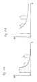
- FIGS. 1A and 1B each show voltage-time profiles for objects with different decay behavior.
- 1A is the voltage-time curve for an object presented with a rapidly decaying decay function.
- this example may be a decay function act of a ferromagnetic object.
- the one shown Voltage-time curve shows at small times first the emitted single pulse, while this is too larger times from the secondary signal, which from the object to be detected is emitted, is superimposed. This falling section of the decay function is characteristic for the object to be detected.
- Fig. 1B is comparable, except that here is a secondary signal is superimposed with a flatter decay function.
- a secondary signal is superimposed with a flatter decay function.
- it could be the decay function of a trade non-ferromagnetic material.
- 1A and 1B show time intervals which correspond to sampling times t 1 , t 2 , t 1 ', t 2 '.
- the respective signal profiles are sampled at these sampling times; the information required for the detection and identification is drawn from this. For example, by integrating the signal profiles during the period t 1 or t 1 ', information about the signal intensity and thus about the object size or the distance of the detector from the object can be obtained. By comparing the sample values t 1 with t 2 or t 1 'with t 2 ', information is obtained about the decay behavior of the secondary signals and thus information about the nature of the object. A large difference between the samples at t 1 and t 2 indicates a rapid decay of the secondary signal, while a small difference between the samples t 1 'and t 2 ' indicates a slow decay of the secondary signal.
- Figure 2 shows the voltage-frequency curve of a voltage-frequency converter (VCO; voltage controlled oscillator).
- VCO voltage-frequency converter
- the voltage U plotted on the ordinate is preferably that of an integrator 16, of voltage dependent on the intensity of the secondary signal.
- the frequency f starts with increasing voltage increases continuously from 0 kHz to about 3 kHz in order to then assume their saturation value above about 3 kHz. Consequently, with a higher intensity of the secondary signal, i.e. higher integration voltage U, one higher frequency value and thus acoustic information about the object size or the distance of the object from the Detector.
- a signal modulation for example, at these frequencies deploy.
- Figure 3 illustrates the operation of a preferred Detector circuit based on a block diagram.
- a pulse transmitter 2 From a pulse transmitter 2 is via a transmitting and receiving coil 4 broadcast a signal.
- This emitted signal generates a secondary signal in an object to be detected, which is through the mediation of the broadcast and Receiving coil 4 overlaid with the primary emitted pulse.
- the superimposed signal is supplied via an amplifier 6, two separate sampling time switches 8, 10.
- the sampling time switches 8, 10 are switched independently of one another by a sampling time conditioning circuit 12, 14.
- the sampling time switch 8 is switched by the influence of the sampling time processing circuit 12, so that the secondary signal is sampled during the period t 1 , t 1 '(cf. FIGS. 1A, 1B).
- the sampling time switch 10 is switched by the sampling time processing circuit 14 for a period of time t 2 , t 2 '(cf. FIGS. 1A, 1B), so that the secondary signal is sampled during a corresponding period of time .
- the output signal of the sampling time switch 8 is now on the one hand fed to an integrator 16, which is a intensity-dependent output voltage U delivers.
- This output voltage U becomes a voltage-frequency converter 18 supplied and implemented in accordance with FIG. 2 in a frequency.
- the Differential amplifier 20 generates one of the difference of Samples and thus the decay behavior of the secondary signal dependent output voltage. This is one Modulator 22 entered.
- the modulation signal generated by the modulator 22 becomes in addition to the integration voltage U from the integrator 16 Voltage-frequency converter 18 entered, so that the voltage-dependent Frequency signal is amplitude modulated.
- the overall signal of the voltage-frequency converter 18 is a signal generator 24, such as a loudspeaker, which is then an acoustic in the manner according to the invention Indicates signal.
- This display signal has two different acoustic characteristics, namely the intensity-dependent tone frequency as well as the modulation frequency depending on the nature of the object.
- the Modulator 22 additionally with an optical display element 26 coupled so that modulation effects over the frequency range go beyond the tone conversion, more recognizable are.
- the acoustic display signal will not be modulated even if the distance between the detector and the object is small and the integration voltage U is large.
- the difference between the samples t 1 ', t 2 ' will be in a range from a certain integration voltage U or audio frequency f, in which a Modulation takes place.
- the modulation can be used at lower or higher sound frequencies.
- the user therefore receives information about the distance of the detector to the object and / or the object size as well as the nature of the object.
- the two principally independent characteristics of the acoustic display signal can surprisingly turn out in the case of special circumstances in their information content support. For example, is the situation that a modulation only with a small distance between If the detector and object are inserted, the audio frequency signal is located possibly already in saturation, i.e. in a range of, for example, 3 kHz. Now set that Modulation on, so a further approximation of the detector by changing the modulation at a constant tone frequency be detected.
- the invention thus represents not just a "two-dimensional mixing function" for object detection and available for object identification, but it continues to increase the dynamic range of the Detector.
- FIG. 4A shows a signal without any modulation. This arises, for example, when the secondary signals emitted by the object to be detected decay quickly and the signal curve therefore makes no or only a small contribution to intensity during the period t 2 (cf. FIG. 1A).
- 4B shows a waveform in which the modulation starts with a low frequency and then a low one Has increased frequency.
- FIG. 4D also shows a signal curve a modulation whose frequency increases rapidly.
Landscapes
- Physics & Mathematics (AREA)
- Life Sciences & Earth Sciences (AREA)
- Engineering & Computer Science (AREA)
- Remote Sensing (AREA)
- Geology (AREA)
- Environmental & Geological Engineering (AREA)
- General Life Sciences & Earth Sciences (AREA)
- General Physics & Mathematics (AREA)
- Geophysics (AREA)
- Acoustics & Sound (AREA)
- Electromagnetism (AREA)
- Geophysics And Detection Of Objects (AREA)
- Measurement Of Velocity Or Position Using Acoustic Or Ultrasonic Waves (AREA)
Applications Claiming Priority (2)
| Application Number | Priority Date | Filing Date | Title |
|---|---|---|---|
| DE19901174A DE19901174C1 (de) | 1999-01-14 | 1999-01-14 | Verfahren und Vorrichtung zur elektromagnetischen Detektion von Objekten |
| DE19901174 | 1999-01-14 |
Publications (3)
| Publication Number | Publication Date |
|---|---|
| EP1020737A2 true EP1020737A2 (fr) | 2000-07-19 |
| EP1020737A3 EP1020737A3 (fr) | 2003-03-26 |
| EP1020737B1 EP1020737B1 (fr) | 2004-11-03 |
Family
ID=7894231
Family Applications (1)
| Application Number | Title | Priority Date | Filing Date |
|---|---|---|---|
| EP99124408A Expired - Lifetime EP1020737B1 (fr) | 1999-01-14 | 1999-12-07 | Procédé et dispositif pour la détection électromagnétique des objets |
Country Status (3)
| Country | Link |
|---|---|
| EP (1) | EP1020737B1 (fr) |
| AT (1) | ATE281655T1 (fr) |
| DE (2) | DE19901174C1 (fr) |
Cited By (2)
| Publication number | Priority date | Publication date | Assignee | Title |
|---|---|---|---|---|
| FR2827677A1 (fr) * | 2001-07-19 | 2003-01-24 | Senstronic Sa | Procede de detection d'un objet en un materiau conducteur et capteur correspondant |
| DE202015102891U1 (de) | 2015-06-03 | 2015-07-17 | Klaus Ebinger | Suchgerät |
Families Citing this family (3)
| Publication number | Priority date | Publication date | Assignee | Title |
|---|---|---|---|---|
| DE10128849C1 (de) * | 2001-06-15 | 2003-01-09 | Vallon Gmbh | Verfahren zur elektromagnetischen Detektion von Objekten mit einem Detektor |
| DE10261258B4 (de) * | 2002-12-27 | 2007-04-05 | Klaus Ebinger | Verfahren zur Detektion von Metallgegenständen und Metalldetektor |
| DE102011004538B4 (de) | 2011-02-22 | 2025-08-14 | Ifm Electronic Gmbh | Induktiver Näherungsschalter und Verfahren zum Ausblenden des Sendepulses |
Family Cites Families (6)
| Publication number | Priority date | Publication date | Assignee | Title |
|---|---|---|---|---|
| US4325027A (en) * | 1979-11-28 | 1982-04-13 | Compass Electronics | Metal detector for locating objects with full sensitivity in the presence of distributed mineral material |
| US4486712A (en) * | 1981-09-25 | 1984-12-04 | Weber Harold J | Frequency dependent pulsed gain modulated metallic object detector |
| DE4212363C2 (de) * | 1992-04-13 | 1997-10-02 | Klaus Ebinger Ing | Metalldetektor |
| US5414411A (en) * | 1993-06-21 | 1995-05-09 | White's Electronics, Inc. | Pulse induction metal detector |
| DE4326030A1 (de) * | 1993-08-03 | 1995-02-09 | Klaus Ebinger | Verfahren zur elektromagnetischen Detektion von Objekten |
| DE19506339C2 (de) * | 1995-02-23 | 1998-01-15 | Klaus Ebinger | Verfahren und Schaltungsvorrichtung zur elektromagnetischen Detektion von Objekten |
-
1999
- 1999-01-14 DE DE19901174A patent/DE19901174C1/de not_active Expired - Fee Related
- 1999-12-07 EP EP99124408A patent/EP1020737B1/fr not_active Expired - Lifetime
- 1999-12-07 DE DE59910986T patent/DE59910986D1/de not_active Expired - Fee Related
- 1999-12-07 AT AT99124408T patent/ATE281655T1/de not_active IP Right Cessation
Cited By (3)
| Publication number | Priority date | Publication date | Assignee | Title |
|---|---|---|---|---|
| FR2827677A1 (fr) * | 2001-07-19 | 2003-01-24 | Senstronic Sa | Procede de detection d'un objet en un materiau conducteur et capteur correspondant |
| EP1293806A3 (fr) * | 2001-07-19 | 2003-11-19 | Senstronic (Société Anonyme) | Procédé de détection d'un objet en un matériau conducteur et capteur correspondant |
| DE202015102891U1 (de) | 2015-06-03 | 2015-07-17 | Klaus Ebinger | Suchgerät |
Also Published As
| Publication number | Publication date |
|---|---|
| ATE281655T1 (de) | 2004-11-15 |
| DE19901174C1 (de) | 2000-10-26 |
| EP1020737A3 (fr) | 2003-03-26 |
| DE59910986D1 (de) | 2004-12-09 |
| EP1020737B1 (fr) | 2004-11-03 |
Similar Documents
| Publication | Publication Date | Title |
|---|---|---|
| DE19847135B4 (de) | Verfahren zum Lesen der in einem Transponder gespeicherten Daten und Transpondersystem zur Durchführung des Verfahrens | |
| DE69425247T2 (de) | Fernbedienungsteuerungssystem, beleuchtungssystem und filter | |
| DE2340187C3 (de) | Verfahren und Vorrichtung zum Erkennen einer elektromagnetische Schwingungen erzeugenden Quelle | |
| DE2002012A1 (de) | Vorrichtung und Verfahren zum Melden von Hindernissen und zur Anzeige der Entfernung der Hindernisse | |
| DE4141468C2 (de) | Optische Sensoranordnung und Verfahren zu deren Betrieb | |
| EP1105986A2 (fr) | Procede permettant de transmettre des informations et systeme associe | |
| DE1261169B (de) | Hoerhilfe | |
| DE2844293B2 (fr) | ||
| EP1020737B1 (fr) | Procédé et dispositif pour la détection électromagnétique des objets | |
| DE3007354C1 (de) | Alarmsystem | |
| DE2539438C3 (de) | Strahlenschranke | |
| DE102017100306B4 (de) | Vorrichtung und Verfahren zur Vermessung einer optischen, kapazitiven, induktiven Übertragungsstrecke mittels Mehrfachmodulation | |
| DE1905680C3 (de) | Anordnung zur Änderung der Dauer frequenzmodulierter Impulse, insbesonde re bei mit Impulsverdichtung arbeiten den Ultraschall Ruckstrahlortungsanlagen | |
| EP1529342B1 (fr) | Procede de deparasitage de signaux de mesure | |
| DE69224806T2 (de) | Warnvorrichtung mit Sektorbedrohungsanzeige | |
| DE102017100305B4 (de) | Vorrichtung und Verfahren zur Vermessung einer optischen, kapazitiven, induktiven Übertragungsstrecke mittels Mehrfachmodulation | |
| EP0509408B1 (fr) | Détecteur de métaux avec acoustique déclenchant un signal | |
| DE2602307C2 (de) | Schaltungsanordnung zum Erfassen und Darstellen des vom Kehlkopf abgegebenen Sprechmusters (Laryngograph) | |
| DE3317569A1 (de) | Auswertung von elektrisch gewandelten schallemissionssignalen | |
| EP0202634A2 (fr) | Dispositif de surveillance de proximité avec source sonore | |
| DE1926362C (de) | Einrichtung zur Sprachanalyse und synthe se nach dem Vocoderpnnzip | |
| DE19904747A1 (de) | Verfahren zur Übertragung von Informationen sowie ein geeignetes System hierfür | |
| DE3115801C2 (fr) | ||
| DE10261258B4 (de) | Verfahren zur Detektion von Metallgegenständen und Metalldetektor | |
| EP1579426A1 (fr) | Procede de transmission de signaux audio d'apres le procede de transmission de pixels par ordre de priorite |
Legal Events
| Date | Code | Title | Description |
|---|---|---|---|
| PUAI | Public reference made under article 153(3) epc to a published international application that has entered the european phase |
Free format text: ORIGINAL CODE: 0009012 |
|
| AK | Designated contracting states |
Kind code of ref document: A2 Designated state(s): AT BE CH CY DE DK ES FI FR GB GR IE IT LI LU MC NL PT SE |
|
| AX | Request for extension of the european patent |
Free format text: AL;LT;LV;MK;RO;SI |
|
| PUAL | Search report despatched |
Free format text: ORIGINAL CODE: 0009013 |
|
| AK | Designated contracting states |
Kind code of ref document: A3 Designated state(s): AT BE CH CY DE DK ES FI FR GB GR IE IT LI LU MC NL PT SE Designated state(s): AT BE CH CY DE DK ES FI FR GB GR IE IT LI LU MC NL PT SE |
|
| AX | Request for extension of the european patent |
Extension state: AL LT LV MK RO SI |
|
| 17P | Request for examination filed |
Effective date: 20030324 |
|
| AKX | Designation fees paid |
Designated state(s): AT DE FR GB IT |
|
| GRAP | Despatch of communication of intention to grant a patent |
Free format text: ORIGINAL CODE: EPIDOSNIGR1 |
|
| RIC1 | Information provided on ipc code assigned before grant |
Ipc: 7G 01V 3/10 A |
|
| RIC1 | Information provided on ipc code assigned before grant |
Ipc: 7G 01V 3/10 A |
|
| GRAS | Grant fee paid |
Free format text: ORIGINAL CODE: EPIDOSNIGR3 |
|
| GRAA | (expected) grant |
Free format text: ORIGINAL CODE: 0009210 |
|
| AK | Designated contracting states |
Kind code of ref document: B1 Designated state(s): AT DE FR GB IT |
|
| REG | Reference to a national code |
Ref country code: GB Ref legal event code: FG4D Free format text: NOT ENGLISH |
|
| REF | Corresponds to: |
Ref document number: 59910986 Country of ref document: DE Date of ref document: 20041209 Kind code of ref document: P |
|
| REG | Reference to a national code |
Ref country code: IE Ref legal event code: FG4D Free format text: GERMAN |
|
| GBT | Gb: translation of ep patent filed (gb section 77(6)(a)/1977) |
Effective date: 20050110 |
|
| REG | Reference to a national code |
Ref country code: IE Ref legal event code: FD4D |
|
| PLBE | No opposition filed within time limit |
Free format text: ORIGINAL CODE: 0009261 |
|
| STAA | Information on the status of an ep patent application or granted ep patent |
Free format text: STATUS: NO OPPOSITION FILED WITHIN TIME LIMIT |
|
| ET | Fr: translation filed | ||
| 26N | No opposition filed |
Effective date: 20050804 |
|
| PGFP | Annual fee paid to national office [announced via postgrant information from national office to epo] |
Ref country code: AT Payment date: 20081218 Year of fee payment: 10 |
|
| PGFP | Annual fee paid to national office [announced via postgrant information from national office to epo] |
Ref country code: IT Payment date: 20081209 Year of fee payment: 10 |
|
| PGFP | Annual fee paid to national office [announced via postgrant information from national office to epo] |
Ref country code: DE Payment date: 20081229 Year of fee payment: 10 |
|
| PGFP | Annual fee paid to national office [announced via postgrant information from national office to epo] |
Ref country code: GB Payment date: 20081203 Year of fee payment: 10 |
|
| PGFP | Annual fee paid to national office [announced via postgrant information from national office to epo] |
Ref country code: FR Payment date: 20081229 Year of fee payment: 10 |
|
| GBPC | Gb: european patent ceased through non-payment of renewal fee |
Effective date: 20091207 |
|
| PG25 | Lapsed in a contracting state [announced via postgrant information from national office to epo] |
Ref country code: AT Free format text: LAPSE BECAUSE OF NON-PAYMENT OF DUE FEES Effective date: 20091207 |
|
| REG | Reference to a national code |
Ref country code: FR Ref legal event code: ST Effective date: 20100831 |
|
| PG25 | Lapsed in a contracting state [announced via postgrant information from national office to epo] |
Ref country code: FR Free format text: LAPSE BECAUSE OF NON-PAYMENT OF DUE FEES Effective date: 20091231 |
|
| PG25 | Lapsed in a contracting state [announced via postgrant information from national office to epo] |
Ref country code: DE Free format text: LAPSE BECAUSE OF NON-PAYMENT OF DUE FEES Effective date: 20100701 |
|
| PG25 | Lapsed in a contracting state [announced via postgrant information from national office to epo] |
Ref country code: GB Free format text: LAPSE BECAUSE OF NON-PAYMENT OF DUE FEES Effective date: 20091207 |
|
| PG25 | Lapsed in a contracting state [announced via postgrant information from national office to epo] |
Ref country code: IT Free format text: LAPSE BECAUSE OF NON-PAYMENT OF DUE FEES Effective date: 20091207 |