EP1020786A2 - Vorrichtung zur Steuerung von Krananlagen, Hebezeugen oder dergleichen - Google Patents
Vorrichtung zur Steuerung von Krananlagen, Hebezeugen oder dergleichen Download PDFInfo
- Publication number
- EP1020786A2 EP1020786A2 EP99125177A EP99125177A EP1020786A2 EP 1020786 A2 EP1020786 A2 EP 1020786A2 EP 99125177 A EP99125177 A EP 99125177A EP 99125177 A EP99125177 A EP 99125177A EP 1020786 A2 EP1020786 A2 EP 1020786A2
- Authority
- EP
- European Patent Office
- Prior art keywords
- rod
- handle element
- signal generation
- movement
- electrical signal
- Prior art date
- Legal status (The legal status is an assumption and is not a legal conclusion. Google has not performed a legal analysis and makes no representation as to the accuracy of the status listed.)
- Withdrawn
Links
- 230000007274 generation of a signal involved in cell-cell signaling Effects 0.000 claims description 13
- 239000011324 bead Substances 0.000 claims description 8
- 230000001939 inductive effect Effects 0.000 claims description 2
- 230000003287 optical effect Effects 0.000 claims description 2
- 210000003811 finger Anatomy 0.000 description 3
- 210000000707 wrist Anatomy 0.000 description 3
- 230000000295 complement effect Effects 0.000 description 1
- 238000010276 construction Methods 0.000 description 1
- 230000008878 coupling Effects 0.000 description 1
- 238000010168 coupling process Methods 0.000 description 1
- 238000005859 coupling reaction Methods 0.000 description 1
- 238000001514 detection method Methods 0.000 description 1
- 210000000245 forearm Anatomy 0.000 description 1
- 238000000034 method Methods 0.000 description 1
- 238000004091 panning Methods 0.000 description 1
- 230000002035 prolonged effect Effects 0.000 description 1
- 230000001681 protective effect Effects 0.000 description 1
- 230000008719 thickening Effects 0.000 description 1
- 210000003813 thumb Anatomy 0.000 description 1
Images
Classifications
-
- G—PHYSICS
- G05—CONTROLLING; REGULATING
- G05G—CONTROL DEVICES OR SYSTEMS INSOFAR AS CHARACTERISED BY MECHANICAL FEATURES ONLY
- G05G9/00—Manually-actuated control mechanisms provided with one single controlling member co-operating with two or more controlled members, e.g. selectively, simultaneously
- G05G9/02—Manually-actuated control mechanisms provided with one single controlling member co-operating with two or more controlled members, e.g. selectively, simultaneously the controlling member being movable in different independent ways, movement in each individual way actuating one controlled member only
- G05G9/04—Manually-actuated control mechanisms provided with one single controlling member co-operating with two or more controlled members, e.g. selectively, simultaneously the controlling member being movable in different independent ways, movement in each individual way actuating one controlled member only in which movement in two or more ways can occur simultaneously
- G05G9/047—Manually-actuated control mechanisms provided with one single controlling member co-operating with two or more controlled members, e.g. selectively, simultaneously the controlling member being movable in different independent ways, movement in each individual way actuating one controlled member only in which movement in two or more ways can occur simultaneously the controlling member being movable by hand about orthogonal axes, e.g. joysticks
- G05G2009/0474—Manually-actuated control mechanisms provided with one single controlling member co-operating with two or more controlled members, e.g. selectively, simultaneously the controlling member being movable in different independent ways, movement in each individual way actuating one controlled member only in which movement in two or more ways can occur simultaneously the controlling member being movable by hand about orthogonal axes, e.g. joysticks characterised by means converting mechanical movement into electric signals
- G05G2009/04755—Magnetic sensor, e.g. hall generator, pick-up coil
Definitions
- the invention relates to a device for controlling crane systems, hoists or the like by converting a pivoting movement into an electrical signal with a fixedly arranged bar, at the free end of the bar a handle element is pivotally mounted in the X, Y and Z directions.
- This device has a pivotable spherical shell-shaped element that covered by a protective cap and firmly connected to it.
- the spherical shell-shaped element corresponds to a grip element.
- Such a device is used in industrial joystick applications for switchgear and control stands used.
- a movable element is the central element of the construction of the device
- a handle element stationary is arranged at the free rod end.
- the rod is pivoted.
- the Swiveling movement of the rod in the X, Y and Z directions is converted into electrical signals implemented, which are then used to control crane systems, hoists or the like Devices can be used.
- the pivotable mounting of the rod leads to that a more or less long rod is always deflected for signal generation must, and the user must move his entire arm. Out For this reason, the user may experience prolonged operation of the Device felt pain in the wrist or forearm.
- the US-PS 4,738,417 relates to a device with a frame on the free End two spherical shells to hold the funds to implement the Pivotal movement and for generating electrical signals are rigidly arranged. Inside the lower spherical shell are bearings for a small swiveling one Lever with the handle element. Due to the well-known technical teaching only Storage of the pivotable lever to the free end of a rigidly arranged Frame or rod. It is proposed to use a smaller lever (motion sensing arm) in a pivotable manner. The load when supporting the Handle hand and when operating the handle element always rests on the motion sensing poor.
- the object of the invention is a more compact structure of the device without To achieve using a pivoting lever.
- the grip element according to the invention contains all for converting the swivel movement into electrical signals relevant means. About replacing and simply pulling off the grip element can quickly and easily make changes to the device for controlling Attachments are made. Due to the type of arrangement, the movable Handle element can also be used as a holding or support handle because there is no lever is pressurized. The swivel movement is direct without using a pivoted lever (motion sensing arm) implemented, the handle element with the Frame or rod connects.
- the brackets ensure that the handle element in X, Y and Z directions can be moved. When the bracket is moved in the X and Y directions the bead is forcibly raised in its bearing shell, so that a Movement in the Z direction occurs.
- the pivotable mounting of the handle element prevents a Part of the device, for example a rod, must be moved.
- the fulcrum of the Movable part of the device will go as far up towards the palm of your hand the user placed that only one emerging from the wrist Pivotal movement must be generated.
- the movable handle element has ideally its pivot axis in its center. However, the pivot axis can can also be placed further outwards in the direction of the edge of the grip element, so that the deflection angle of the grip element with its associated pivot axis the respective application and the respective user can be coordinated.
- the pivoting movement of the grip element is realized in that the Device part is connected to the handle element via a kind of ball joint.
- the ball held under spring tension in a pan allows the Handle element always returns to its original position.
- the means for signal generation can by at least one sliding contacts having code carrier and by at least one with the sliding contacts in Connectable grinder be formed. In this way, a Converting the pivoting movement of the handle element into an electrical signal. Here the grinder comes into contact with the sliding contacts, so that an electrical Circuit is closed. By the number of pulses each time generated when the grinder is connected to one of the sliding contacts brought, the pivoting movement of the grip element can be determined.
- the means for signal generation can for example inductive or capacitive means for signal generation may be provided.
- the means for signal generation can also be optical sensors or Hall sensors Include detection of the pivoting movement of the grip element.
- Means can also be provided for potentiometric signal generation.
- the generated ones can be used Signals are transmitted using the multiplex method (2 wire or bus coupling).
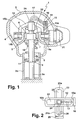
- the device 1 shows the manner in which a device 1 for converting a swiveling movement which can be carried out by hand into an electrical signal is constructed.
- the device 1 comprises a movably mounted device part, a handle element 2, and a stationary device part, a rod 3a and a sleeve 3b surrounding the rod 3a, which are mounted on a control station, not shown in the figure.
- the handle element 2 is pivotably mounted on the rod 3a by means of a type of ball joint.
- the shape of the grip element 2 is such that it can be placed in the palm of a user's hand for actuation.
- On the inside 4 of the grip element 2, a holder 5 is provided, which has a central bearing shell 6.
- the rod 3a thickening spherical bead 7 is movably mounted and fixed against slipping out, so that the grip element 2 can be deflected in the X, Y and Z directions.
- the bead 7 and the bearing shell 6 are designed to be complementary to one another.
- a tension spring 9 is arranged, which is supported on the sections 10 and 11 which are displaceable on the rod 3a. For this reason, the bead 7 is always retracted into its rest position in the bearing shell 6.
- a first bracket 12 is pivoted, which is rotatable on both sides on axes 14a and 14b is stored.
- a grinder 16 is attached is deflected together with the first bracket 12.
- cables 17 can be connected to a central, formed in the direction of the longitudinal axis bore rod 3a from the Handle element 2 are brought out to the outside.
- the grinder 16 has a comb-like shape Finger 18 on, the sliding contacts on a code carrier 19 can scan. If the Finger 18 will come into contact with the sliding contacts of the code carrier 19 an electrical circuit is closed.
- the number of generated electrical impulses corresponds to the rotational movement of the first bracket 12.
- a Pivotal movement of the first bracket 12 out of the plane of the drawing can thus be recorded.
- the pivoting movement of the grip element 2 is limited because of the Sleeve 3b serves as a cover for the rod 3a and as a stop for the grip element 2.
- a second bracket 20 is formed, which is analogous to Bracket 12 is formed and also with a grinder, not shown in FIG. 1 connected is. This grinder is moved with the second bracket 20, so that a Scanning of another code carrier not visible in the figure comes about.
- Additional pushbuttons or switches can be easily reached e.g. in the thumb area as Sliding switches can be arranged for forward-backward travel.
- the simplified top view - for the sake of clarity, further housing parts of the grip element 2 are omitted - illustrates the arrangement of the first and second bracket 12 and 20 according to FIG. 2 .
- the first bracket 12 is rotatably supported in its edge regions 15a and 15b.
- the second bracket 20 is also pivotally mounted in its edge regions 21a and 21b. 1 can be moved in the X, Y and Z directions because both the first bracket 12 and the second bracket 20 have longitudinal slots 22 and 23 through which the free end 24 of the rod 3a passes is.
- the brackets 12 and 20 are displaceable relative to the rod end 24 by means of the longitudinal slots 22 and 23.
- the grinders 16 and 25 are firmly connected to the brackets 12 and 20. Cables 17 and 26 can be led out of the grip element 2 via the central bore in the rod 3a.
- a grip element 2 is provided for a device 1 which is used to implement a Serves pivotal movement in an electrical signal and a fixedly arranged Device part 3 has. On the device part 3 that is with means for Signal generation 16 to 19 connected handle element 2 in the X, Y and Z directions pivoted. For this reason, only one from the wrist of the User pivotable movement of the handle element 2 in a electrical signal can be implemented.
Landscapes
- Physics & Mathematics (AREA)
- General Physics & Mathematics (AREA)
- Engineering & Computer Science (AREA)
- Automation & Control Theory (AREA)
- Finish Polishing, Edge Sharpening, And Grinding By Specific Grinding Devices (AREA)
- Carriers, Traveling Bodies, And Overhead Traveling Cranes (AREA)
Abstract
Description
- Fig. 1
- einen Längsschnitt durch eine Vorrichtung zur Umsetzung einer Schwenkbewegung in ein elektrisches Signal;
- Fig. 2
- eine Draufsicht auf den Schwenkmechanismus der Vorrichtung nach Fig. 1.
- 1
- Vorrichtung
- 2
- Griffelement
- 3a
- Stange
- 3b
- Hülse
- 4
- Innenseite
- 5
- Halter
- 6
- Lagerschale
- 7
- Wulst
- 8
- Stützring
- 9
- Spannfeder
- 10
- Abschnitt
- 11
- Abschnitt
- 12
- Erster Bügel
- 14a
- Drehachse
- 14b
- Drehachse
- 15a
- Randbereich
- 15b
- Randbereich
- 16
- Schleifer
- 17
- Kabel
- 18
- Finger
- 19
- Codeträger
- 20
- Zweiter Bügel
- 21a
- Randbereich
- 21b
- Randbereich
- 22
- Längsschlitz
- 23
- Längsschlitz
- 24
- Stangenende
- 25
- Schleifer
- 26
- Kabel
Claims (7)
- Vorrichtung (1) zur Steuerung von Krananlagen, Hebezeugen oder dergleichen durch Umsetzung einer Schwenkbewegung in ein elektrisches Signal mit einer ortsfest angeordneten Stange (3a), an deren freiem Stangenende (24) ein Griffelement (2) in X-, Y- und Z-Richtung schwenkbar gelagert ist, dadurch gekennzeichnet, dass die Stange (3a) unterhalb ihres freien Stangenendes (24) einen die Stange (3a) umgebenden, in einer Lagerschale (6) des Griffelements (2) gehaltenen Wulst (7) mit einer kugelförmigen Wulstfläche aufweist, und dass im Griffelement (2) zwei orthogonal zueinander angeordnete Bügel (12,20) schwenkbar gelagert sind, die Längsschlitze (22,23) zur Hindurchführung des freien Stangenendes (24) besitzen und mit Mitteln (16 bis 19) zur Erzeugung eines elektrischen Signals verbunden sind.
- Vorrichtung nach Anspruch 1, dadurch gekennzeichnet, dass die Mittel zur Signalerzeugung durch mindestens einen Schleifkontakte aufweisenden Codeträger (19) und durch mindestens einen mit den Schleifkontakten in Verbindung bringbaren Schleifer (16) ausgebildet sind.
- Vorrichtung nach Anspruch 1, dadurch gekennzeichnet, dass induktive Mittel zur Signalerzeugung vorgesehen sind.
- Vorrichtung nach Anspruch 1, dadurch gekennzeichnet, dass kapazitive Mittel zur Signalerzeugung vorgesehen sind.
- Vorrichtung nach Anspruch 1, dadurch gekennzeichnet, dass die Mittel zur Signalerzeugung optische Sensoren zur Erfassung der Bewegung des Griffelements umfassen.
- Vorrichtung nach Anspruch 1, dadurch gekennzeichnet, dass die Mittel zur Signalerzeugung Hall-Sensoren zur Erfassung der Bewegung des Griffelements umfassen.
- Vorrichtung nach Anspruch 1, dadurch gekennzeichnet, *dass Mittel zur potentiometrischen Signalerzeugung vorgesehen sind.
Applications Claiming Priority (2)
| Application Number | Priority Date | Filing Date | Title |
|---|---|---|---|
| DE19901330 | 1999-01-15 | ||
| DE1999101330 DE19901330C2 (de) | 1999-01-15 | 1999-01-15 | Griffelement |
Publications (2)
| Publication Number | Publication Date |
|---|---|
| EP1020786A2 true EP1020786A2 (de) | 2000-07-19 |
| EP1020786A3 EP1020786A3 (de) | 2002-12-18 |
Family
ID=7894333
Family Applications (1)
| Application Number | Title | Priority Date | Filing Date |
|---|---|---|---|
| EP99125177A Withdrawn EP1020786A3 (de) | 1999-01-15 | 1999-12-17 | Vorrichtung zur Steuerung von Krananlagen, Hebezeugen oder dergleichen |
Country Status (3)
| Country | Link |
|---|---|
| EP (1) | EP1020786A3 (de) |
| DE (1) | DE19901330C2 (de) |
| NO (1) | NO20000186L (de) |
Cited By (4)
| Publication number | Priority date | Publication date | Assignee | Title |
|---|---|---|---|---|
| WO2003095352A1 (en) * | 2002-05-08 | 2003-11-20 | The Stanley Works | Methods and apparatus for manipulation of heavy payloads with intelligent assist devices |
| FR2880436A1 (fr) * | 2004-12-30 | 2006-07-07 | Itt Mfg Enterprises Inc | Actionneur multidirectionnel dont l'organe d'actionnement est pivotant autour de son centre |
| EP2078999A2 (de) | 2008-01-10 | 2009-07-15 | Honeywell International Inc. | Kardananordnung mit flexiblen Substratkabelbäumen |
| EP2006757A3 (de) * | 2001-06-01 | 2012-05-30 | Kawasaki Jukogyo Kabushiki Kaisha | Joystickgerät |
Families Citing this family (2)
| Publication number | Priority date | Publication date | Assignee | Title |
|---|---|---|---|---|
| DE10065847A1 (de) * | 2000-12-27 | 2002-07-11 | Demag Cranes & Components Gmbh | Vorrichtung zur Handsteuerung, insbesondere eines Fahr- und/oder Hubantriebs einer Lasthebevorrichtung |
| US8985354B2 (en) * | 2011-11-04 | 2015-03-24 | GM Global Technology Operations LLC | Movement system configured for moving a payload in a plurality of directions |
Citations (1)
| Publication number | Priority date | Publication date | Assignee | Title |
|---|---|---|---|---|
| US4738417A (en) | 1987-02-02 | 1988-04-19 | Fmc Corporation | Hand operated control |
Family Cites Families (5)
| Publication number | Priority date | Publication date | Assignee | Title |
|---|---|---|---|---|
| DE1178258B (de) * | 1959-06-19 | 1964-09-17 | Contraves Ag | Handbetaetigbares Steuergeraet |
| JPS5229815B2 (de) * | 1972-09-06 | 1977-08-04 | ||
| US4148014A (en) * | 1977-04-06 | 1979-04-03 | Texas Instruments Incorporated | System with joystick to control velocity vector of a display cursor |
| FR2434426A1 (fr) * | 1978-07-06 | 1980-03-21 | Renault | Dispositif manuel de commande de robot |
| US4580006A (en) * | 1984-06-14 | 1986-04-01 | Hull Daniel T | Method and apparatus for providing two dimensional positioning data signals |
-
1999
- 1999-01-15 DE DE1999101330 patent/DE19901330C2/de not_active Expired - Fee Related
- 1999-12-17 EP EP99125177A patent/EP1020786A3/de not_active Withdrawn
-
2000
- 2000-01-14 NO NO20000186A patent/NO20000186L/no not_active Application Discontinuation
Patent Citations (1)
| Publication number | Priority date | Publication date | Assignee | Title |
|---|---|---|---|---|
| US4738417A (en) | 1987-02-02 | 1988-04-19 | Fmc Corporation | Hand operated control |
Cited By (7)
| Publication number | Priority date | Publication date | Assignee | Title |
|---|---|---|---|---|
| EP2006757A3 (de) * | 2001-06-01 | 2012-05-30 | Kawasaki Jukogyo Kabushiki Kaisha | Joystickgerät |
| WO2003095352A1 (en) * | 2002-05-08 | 2003-11-20 | The Stanley Works | Methods and apparatus for manipulation of heavy payloads with intelligent assist devices |
| US7185774B2 (en) | 2002-05-08 | 2007-03-06 | The Stanley Works | Methods and apparatus for manipulation of heavy payloads with intelligent assist devices |
| FR2880436A1 (fr) * | 2004-12-30 | 2006-07-07 | Itt Mfg Enterprises Inc | Actionneur multidirectionnel dont l'organe d'actionnement est pivotant autour de son centre |
| EP2078999A2 (de) | 2008-01-10 | 2009-07-15 | Honeywell International Inc. | Kardananordnung mit flexiblen Substratkabelbäumen |
| EP2078999A3 (de) * | 2008-01-10 | 2010-01-20 | Honeywell International Inc. | Kardananordnung mit flexiblen Substratkabelbäumen |
| US8136421B2 (en) | 2008-01-10 | 2012-03-20 | Honeywell International Inc. | Gimbal assembly including flexible substrate wiring harnesses |
Also Published As
| Publication number | Publication date |
|---|---|
| NO20000186D0 (no) | 2000-01-14 |
| EP1020786A3 (de) | 2002-12-18 |
| DE19901330C2 (de) | 2001-04-19 |
| NO20000186L (no) | 2000-07-17 |
| DE19901330A1 (de) | 2000-08-24 |
Similar Documents
| Publication | Publication Date | Title |
|---|---|---|
| EP2652568B1 (de) | Einrichtung zur programmierung einer handhabungsvorrichtung | |
| DE10310056B4 (de) | Multifunktionsschalter | |
| DE102016011698A1 (de) | Mit Griffen versehene Roboterbedienvorrichtung zum Bedienen eines Roboters | |
| DE3787372T2 (de) | Steuermechanismus für rechnertastatur und dergleichen. | |
| DE602004006227T2 (de) | Benutzerschnittstellenvorrichtung | |
| EP3081347B1 (de) | Roboter-bedienhandgerät, ein damit elektronisch kommunizierendes gerät und system | |
| DE69814655T2 (de) | Zeigevorrichtung mit integriertem schalter | |
| EP3541582B1 (de) | Roboterbedienhandgerät, zugehörige kopplungsvorrichtung, roboter und verfahren | |
| EP3558602B1 (de) | Robotersteuerpult mit einem zusätzlichen halter für einen tablet-computer | |
| DE19952560C2 (de) | Verfahren zum Ein- und/oder Verstellen eines Kraftfahrzeugsitzes, von Teilen des Kraftfahrzeugsitzes und /oder von den Fahrer unterstützenden Einrichtungen und Vorrichtung zur Durchführung des Verfahrens | |
| DE10027754A1 (de) | Vorrichtung zum Abtasten von Arbeitshöhen | |
| DE60308632T2 (de) | Taststift mit einstellbarer Orientierung | |
| EP1456808A1 (de) | Vorrichtung zum erfassen und darstellen von bewegungen | |
| EP1020786A2 (de) | Vorrichtung zur Steuerung von Krananlagen, Hebezeugen oder dergleichen | |
| WO2012139946A1 (de) | Bestimmung der position eines kontaktstabes an einem sonden-halter einer hüttentechnischen sonde | |
| DE102018109326A1 (de) | Mehrgliedrige aktuierte Kinematik, vorzugsweise Roboter, besonders vorzugsweise Knickarmroboter | |
| WO2010006741A1 (de) | Bedienelement zur einhandbedienung ophthalmologischer geräte | |
| EP0558884A1 (de) | Handbetätigte Stellvorrichtung für einen Bedienungsstand bzw. -sitz | |
| EP1096419B1 (de) | Eingabegerät | |
| DE29923670U1 (de) | Griffelement | |
| DE10259009B3 (de) | Bedieneinheit für ein optisches System | |
| DE102019124358B4 (de) | Manipulator | |
| DE3418319C2 (de) | ||
| DE3209208A1 (de) | Elektrische pruefspitze | |
| DE102008064021A1 (de) | Bedieneinheit, insbesondere für ein Fahrzeug |
Legal Events
| Date | Code | Title | Description |
|---|---|---|---|
| PUAI | Public reference made under article 153(3) epc to a published international application that has entered the european phase |
Free format text: ORIGINAL CODE: 0009012 |
|
| AK | Designated contracting states |
Kind code of ref document: A2 Designated state(s): AT BE CH CY DE DK ES FI FR GB GR IE IT LI LU MC NL PT SE |
|
| AX | Request for extension of the european patent |
Free format text: AL;LT;LV;MK;RO;SI |
|
| PUAL | Search report despatched |
Free format text: ORIGINAL CODE: 0009013 |
|
| AK | Designated contracting states |
Kind code of ref document: A3 Designated state(s): AT BE CH CY DE DK ES FI FR GB GR IE IT LI LU MC NL PT SE |
|
| AX | Request for extension of the european patent |
Free format text: AL;LT;LV;MK;RO;SI |
|
| AKX | Designation fees paid | ||
| REG | Reference to a national code |
Ref country code: DE Ref legal event code: 8566 |
|
| STAA | Information on the status of an ep patent application or granted ep patent |
Free format text: STATUS: THE APPLICATION IS DEEMED TO BE WITHDRAWN |
|
| 18D | Application deemed to be withdrawn |
Effective date: 20030619 |