EP1021068A2 - Procédé de décongélation micro-ondes - Google Patents
Procédé de décongélation micro-ondes Download PDFInfo
- Publication number
- EP1021068A2 EP1021068A2 EP00300261A EP00300261A EP1021068A2 EP 1021068 A2 EP1021068 A2 EP 1021068A2 EP 00300261 A EP00300261 A EP 00300261A EP 00300261 A EP00300261 A EP 00300261A EP 1021068 A2 EP1021068 A2 EP 1021068A2
- Authority
- EP
- European Patent Office
- Prior art keywords
- magnetron
- defrosting
- microcomputer
- sensor
- defrosting method
- Prior art date
- Legal status (The legal status is an assumption and is not a legal conclusion. Google has not performed a legal analysis and makes no representation as to the accuracy of the status listed.)
- Granted
Links
Images






Classifications
-
- F—MECHANICAL ENGINEERING; LIGHTING; HEATING; WEAPONS; BLASTING
- F24—HEATING; RANGES; VENTILATING
- F24C—DOMESTIC STOVES OR RANGES ; DETAILS OF DOMESTIC STOVES OR RANGES, OF GENERAL APPLICATION
- F24C7/00—Stoves or ranges heated by electric energy
- F24C7/08—Arrangement or mounting of control or safety devices
-
- H—ELECTRICITY
- H05—ELECTRIC TECHNIQUES NOT OTHERWISE PROVIDED FOR
- H05B—ELECTRIC HEATING; ELECTRIC LIGHT SOURCES NOT OTHERWISE PROVIDED FOR; CIRCUIT ARRANGEMENTS FOR ELECTRIC LIGHT SOURCES, IN GENERAL
- H05B6/00—Heating by electric, magnetic or electromagnetic fields
- H05B6/64—Heating using microwaves
- H05B6/66—Circuits
- H05B6/68—Circuits for monitoring or control
- H05B6/687—Circuits for monitoring or control for cooking
Definitions
- the present invention relates to a method of operating a microwave oven to defrost an item.
- Microwave ovens are well known and are used to cook food by irradiating it with microwaves.
- the microwaves cause water molecules in the food to vibrate thereby raising the temperature of the food.
- Microwave ovens are usually provided with a defrosting function for defrosting frozen food.
- a defrosting function for defrosting frozen food.
- the frozen food is placed in a cooking chamber of the microwave oven and weight of the food is input.
- a controller part of the microwave oven adjusts the output power of the oven's magnetron in dependence on the input weight.
- the controller part of the microwave oven drives the magnetron for the input time with a corresponding magnetron power output level.
- the user When the user inputs the defrosting time, the user usually sets the defrosting time by guesswork, preference, or based on past experience. Consequently, optimal defrosting is rarely achieved.
- defrosting is performed using a constant power level and is not controlled in dependence on the state of the food being defrosted during the defrosting process. This means that the user must open the oven's door to inspect the food to determine how the defrosting is progressing and adjust the defrosting time as the user deems necessary.
- a method according to the present invention is characterised by:-
- the microwave energy applied may be controlled in dependence on the change in said parameter across one interval.
- the microwave energy applied is controlled in dependence on the changes, if any, in said parameter over a plurality of intervals.
- the method preferably includes determining the time and value differences between a minimum and a maximum for said parameter, wherein the microwave energy applied is controlled in dependence on said differences, and/or determining the substantial absence of change in said parameter over a predetermined plurality of said intervals and terminating the application of microwave energy in response thereto.
- microwave oven configured to operate according to a method according to the present invention.
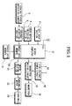
- a microwave oven includes a key input section 2, a door position detection switching section 4, a cooking status detection sensor 6, e.g. a standing wave sensor in the oven's waveguide, a voltage detecting section 8, a status data memory 10, a microcomputer 12 having a memory 12A, a high voltage power circuit 14, a magnetron driving circuit 16, a magnetron 18, a motor driving section 20, a turntable motor 22, and a turntable 24.
- the key input section 2 includes a plurality of cooking item buttons for set various cooking conditions, a cooking start button and a defrosting start button.
- the door position detection switching section 4 detects whether the oven's cooking chamber door is open or closed and generates a corresponding door position signal.
- the cooking status detecting sensor 6 employs an antenna disposed in a waveguide of the microwave oven for detecting the magnetic field of the standing wave in the waveguide formed by the superposition of the forward wave from the magnetron 18 and the reflected wave from the defrosting food.
- the antenna is as disclosed KR-A-98-161026 and KR-U-99-143508.
- the cooking status detecting sensor 6 may include a plurality of sensors such as infrared sensors and temperature sensors for detecting the temperature of food, humidity sensors and gas sensors for detecting water vapour and gas from the food, light emitting and receiving elements for detecting the shape of the food, etc..
- the voltage detecting section 8 accurately detects voltage signals from the cooking status detecting sensor 6. If the cooking status detecting sensor 6 is an antenna, the voltage detecting section 8 includes a diode for rectifying the output voltage of the antenna, a smoothing capacitor for smoothing the rectified voltage and a resistor.
- the status data memory 10 is used to store the defrosting status detecting data which is a result of regularly sampling the output of the cooking status detecting sensor 6 and values calculated therefrom.
- the microcomputer 12 drives the magnetron 18 at a power level appropriate for the food being defrosted and rotates the turntable 24, which carries the food, a predetermined speed.
- one turntable rotation period means a predetermined number of turntable revolutions.
- the microcomputer 12 receives data from the cooking status detecting sensor 6.
- the microcomputer 12 calculates the difference between the data for the present turntable rotation period and a previous one and adjusts the magnetron output power accordingly.
- the memory 12A stores a control program controlling the microcomputer 12 for adjusting the magnetron power level for the defrosting function and for processing the defrosting status detect data obtained from the cooking status detecting sensor 6.
- the magnetron driving circuit 16 receives high-voltage power from the high-voltage power circuit 14 to drive the magnetron 18.
- the motor driving section 20 controlled by the microcomputer 12 to drive the turntable motor 22 to rotate the turntable 24 at the predetermined speed.
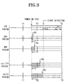
- the microcomputer 12 collects the voltage signals which are output by the cooking status detecting sensor 6 when the turntable 24 is at a plurality of detecting positions (P 1 , P 2 , P 3 , P 4 , ..., P n-3 , P n-2 , P n-1 , P n ) on the regular basis when the magnetron 18 is on.
- the microcomputer 12 sets three rotations of the turntable 24 (T1, T2, T3; See Figure 3) as one turntable rotation period and cycles the magnetron 18 on and off once in each turntable rotation period, i.e., during every thee revolutions of the turntable 24.
- One rotation of the turntable 24 takes 10 seconds, and accordingly, the speed of the turntable 24 is 6 rpm.
- the microcomputer 12 operates the magnetron 18 during a portion of the turntable rotation period, which comprises thee revolutions T1, T2, T3 of the turntable 24. While the magnetron 18 is on, the microcomputer 12 samples the voltage signals from the cooking status detecting sensor 6 at positions P 1 , P 2 , P 3 , P 4 , ..., P n-3 , P n-2 , P n-1 , P n of the turntable 24.
- the microcomputer 12 calculates the difference between the data obtained from the present turntable rotation period and that from a previous turntable rotation period, and adjusts the magnetron power-on period for the next turntable rotation period in accordance with the calculated difference.
- the magnetron power-on period is gradually shortened by a compensating value which is obtained from the difference between the data detected from the respective turntable rotation periods and the respective preceding turntable rotation periods. Accordingly, the magnetron power-on time PO is delayed as the magnetron power-on period is shortened. Also, as the power-on time PO is delayed, the power-off period is gradually increased so that the turntable rotation period remains constant.
- the magnetron power-off period t off (n+1) is accordingly increased, while, as the magnetron power-on period t on (n+1) is increased, the magnetron power-off period t off (n+1) is decreased.
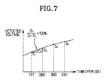
- the voltage values obtained from the cooking status detecting sensor 6 from the first turntable rotation period to the n th turntable rotation period are vary as defrosting progresses.
- S 1 , S 2 , S 3 , ..., S n-1 , S n are the accumulations of the detected voltage values which are collected from the cooking status detecting sensor 6 during the power-on periods of respective turntable rotation periods.
- the accumulation of the detected voltage values of the respective turntable rotation periods will be called the "detected data”.
- the microcomputer 12 calculates the differences between the detected data (S 1 , S 2 , S 3 ,,,, S n ) for pairs of successive turntable rotation periods. The calculated differences are used as the compensating values for adjusting the next magnetron power-on period t on (n+1).
- the microcomputer 12 calculates the difference between the detected data (S 3 ) from the third turntable rotation period and the detected data (S 2 ) from the second turntable rotation period, and adjusts the magnetron power output requirement in accordance with the calculated difference.
- the adjusted magnetron output power requirement is used for adjusting the magnetron power-on period t on (n+1) in the fourth turntable rotation period.
- the microcomputer 12 calculates the difference between the detected data (S 1 ) and (S 2 ⁇ S n ) detected by the cooking status detecting sensor 6 during the first turntable rotation period and the second to the n th turntable rotation periods, respectively.
- the respective differences calculated between the detected data (S 1 ) and the respective detected data (S 2 ⁇ S n ) from the first turntable rotation period and the second to the n th turntable rotation periods are used as the compensating values for adjusting the magnetron power-on period t on (n+1) for the next respective turntable rotation periods.
- the food to be defrosted is placed in the cooking chamber of the microwave oven, and the cooking chamber door is closed. Then, the door position detection switching section 4 generates the door closed switching signal.
- the microcomputer 12 receives the door closed switching signal and sets the microwave oven on standby for defrosting operation (step ST10).
- step ST11 the microcomputer 12 determines whether then defrosting start key has been pressed.
- the microcomputer 12 drives the magnetron driving circuit 16 so that the magnetron 18 generates microwaves at a level appropriate for defrosting operation. Also, the microcomputer 12 drives the motor driving section 20 so that the turntable motor 22 is rotated to rotate the turntable 24 at a predetermined speed (step ST12).
- the microcomputer 12 regularly receives the voltage signals from the cooking status detecting sensor 6 when the turntable 24 is at the aforementioned positions P 1 , P 2 , P 3 , P 4 , ..., P n-3 , P n-2 , P n-1 , P n and thus collects the data (step ST13).
- the microcomputer 12 determines whether one turntable rotation period is completed at step ST14. If the microcomputer 12 determines that a turntable rotation period has been completed, the microcomputer 12 switches off the magnetron 18 (step ST15). Next, the microcomputer 12 accumulates the data collected from the cooking status detecting sensor 6 during the magnetron power-on period and calculates the difference between it an the previous value (step ST16). That is, as shown in Figure 5A, the microcomputer 12 calculates the absolute difference (
- the microcomputer 12 may calculate the absolute differences between the detected data (S 1 ) for the first turntable rotation period and the detected data (S 2 ⁇ S n ) for the present turntable rotation period. The calculated difference is used as a compensating value for adjusting the magnetron output power for the next turntable rotation period. After that, the microcomputer 12 determines whether the defrosting has been completed based on the calculation of the collected data (step ST17).
- the microcomputer 12 adjusts the magnetron power-on period by applying the compensating value from step ST18, and repeats steps ST12 to ST17.
- the magnetron power-on period is gradually reduced for successive turntable rotation periods and the magnetron power-off periods are gradually extended.
- the microcomputer 12 terminates the defrosting process (step ST19).
- the microcomputer 12 determines the slopes of the curves between the data points for successive turntable rotation periods. The slopes are compared with reference data regarding the magnetron output power adjustment range and the microcomputer 12 selects the most appropriate value in dependence on the slopes. The magnetron output power is adjusted according to the most appropriate value.
- a control program embodying a control algorthm for adjusting the magnetron output power as a function of the slopes, is stored in the memory 12A.
- a plurality of magnetron output power adjust ranges are stored in the memory 12A in table form.
- the slopes of the curves between successive data points obtained from the output of the cooking status detecting sensor 6 during successive turntable rotation periods is calculated.
- the calculated slope is compared with a plurality of reference values and the appropriate magnetron output power adjustment value is selected for use as the actual magnetron output power adjustment value.
- the magnetron output power adjustment value for a slope (S n -S n-1 ) is obtained by the following formula 5: S L ⁇ S n -S n-1 ⁇ S H where, S L and S H are the lowest and highest permitted values of the magnetron output power adjustment value.
- the lowest and highest coefficients (K L and K H ) are expressed as percentages for adding to and subtracting from the magnetron output power, and are stored in the memory 12A.
- the slope of the curves between the data points for successive turntable rotation periods can be processed as a percentage in the above formula 6 and the percentage value can be used for determining the necessary change in the magnetron power-on period for the following turntable rotation period.
- the food to be defrosted is placed in the cooking chamber of the microwave oven, and the cooking chamber door is closed. Then, the door position detection switching section 4 generates the door closed switching signal.
- the microcomputer 12 receives the door closed switching signal and sets the microwave oven on standby for defrosting operation (step ST20).
- step ST21 the microcomputer 12 determines whether then defrosting start key has been pressed.
- the microcomputer 12 drives the magnetron driving circuit 16 so that the magnetron 18 generates microwaves at a level appropriate for defrosting operation. Also, the microcomputer 12 drives the motor driving section 20 so that the turntable motor 22 is rotated to rotate the turntable 24 at a predetermined speed (step ST22).
- the microcomputer 12 regularly receives the voltage signals from the cooking status detecting sensor 6 when the turntable 24 is at the aforementioned positions P 1 , P 2 , P 3 , P 4 , ..., P n-3 , P n-2 , P n-1 , P n and thus collects the data (step ST23).
- the microcomputer 12 determines whether one turntable rotation period is completed at step ST24. If the microcomputer 12 determines that a turntable rotation period has been completed, the microcomputer 12 switches off the magnetron 18 (step ST25). Next, the microcomputer 12 process the data collected from the cooking status detecting sensor 6 during the magnetron power-on period (step ST26). That is, the microcomputer 12 calculates the slope of the curve between the data points for the present and previous turntable rotation periods and selects the appropriate magnetron output power adjust value from the memory 12A.
- the microcomputer 12 determines whether or not the actual slope falls into the range between the minimum and maximum values S L and S H (step ST27). If it is determined that the actual slope falls outside the permitted range S L to S H , the microcomputer 12 substitutes the lowest and highest coefficients (K L and K H ) with another lowest and highest coefficients (K L and K H ) (step ST28), and obtains the minimum and maximum values S L and S H by another lowest and highest coefficients (K L and K H ) on the step ST26, and proceeds to the step ST27.
- the microcomputer 12 determines whether the data in the memory 12A includes a magnetron output power adjustment value for completing the defrosting operation (step ST29).
- the microcomputer 12 adjusts the magnetron power-on period in accordance with the adjustment percentage obtained from the lowest and highest coefficients (K L and K H ) of the magnetron output power adjustment range (step ST30), and proceeds to the step ST22.
- step ST31 If it is determined that the data does include data for completing defrosting operation, the microcomputer 12 completes the defrosting operation (step ST31).
- the microcomputer 12 After the turntable 24 is rotated for a certain period comprising a plurality of turntable rotation periods, the microcomputer 12 detects the change in the slope of the curve joining the data points for different turntable rotation periods. Then the microcomputer 12 obtains the defrosting completion time by determining whether the food in the microwave oven is a light load, a heavy load or no load, in accordance with the degree of the change in the slope of the detected data curve for the certain period.
- a control program implementing a control algorithm for determining completion of defrosting is stored in the memory 12A.
- the load status of the food is determined by multiplying the slopes (d n and d n-1 ) and drawing the following inferences: d n ⁇ d n-1 ⁇ 0 ⁇ light load d n ⁇ d n-1 > 0 ⁇ heavy load d n ⁇ d n-1 ⁇ 0 ⁇ no load
- the product of the slopes will be less than "0", if one is positive and the other is negative.
- step ST40 the microwave oven is on standby for defrosting operation and the microcomputer 12 determines whether the defrosting start key has been pressed (step ST41).
- the microcomputer 12 Upon determining that the defrosting start key has been pressed, the microcomputer 12 controls the magnetron 18 to generate microwaves for defrosting. Also, the microcomputer 12 rotates the turntable 24 at a predetermined speed (step ST42).
- the microcomputer 12 regularly receives voltage signals from the voltage detecting section 8 reporting the standing wave magnitude (step ST43).
- the microcomputer 12 determines whether a turntable rotation period corresponding to three rotations of the turntable 24 has been completed at step ST44.
- step ST45 When the microcomputer 12 determines that a turntable rotation period has been completed, the microcomputer 12 switches off the magnetron 18 (step ST45).
- the microcomputer 12 processes the data collected from the cooking status detecting sensor 6 during the magnetron power-on period (step ST46), and adjusts the magnetron power-on and -off periods accordingly (step ST47).
- the microcomputer 12 determines whether the turntable 24 has been rotated for a predetermined time period, such as for two turntable rotation periods (step ST48).
- the microcomputer 12 When determining that a predetermined period is elapsed, the microcomputer 12 obtains the slopes (d n-1 , d n ) by calculating the differences between the first and second data points and the second and third data points for three successive turntable rotation periods. Then, the microcomputer 12 multiplies the slopes ( d n ⁇ d n-1 ), to determine the load (step ST49). By the multiplication of the respective slopes ( d n ⁇ d n-1 ), the microcomputer 12 determines whether the load of food is light or heavy or whether there is a no load condition (step ST50).
- step ST51 the microcomputer 12 proceeds to the step ST42 and drives the magnetron 18 in accordance with the magnetron power on/off periods adjusted in step ST47. If it is determined that there is a no load condition (step ST52), the microcomputer 12 stops driving the magnetron 18 to immediately terminate the defrosting operation (step ST53).
- step ST50 If the load is determined to be light at step ST50, the microcomputer 12 also terminates the defrosting operation (step ST53).
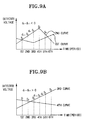
- the microcomputer 12 fits a cubic curve to the detected data, i.e. the accumulated total of the detected voltages from the respective turntable rotation periods. Then the microcomputer 12 differentiates the equation for cubic equation to obtain the maximum and minimum points of the cubic curve and adjusts the power of magnetron or determines the defrosting completion time from these values.
- a control program implementing a control algorithm for fitting a cubic curve to the data points, controlling the magnetron power and determining defrosting completion, is stored in the memory 12A.
- the microcomputer 12 calculates the time (t2-t1) between the maximum and the minimum (f(t1) and f(t2)) and the difference between the maximum and the minimum ( f(t1)-f(t2) ). The microcomputer 12 utilises these difference values for analysing the type and weight of the defrosting food.
- the difference value can be utilised as the compensating values for adjusting the magnetron power, or utilised as the values for a calculation for obtaining the defrosting completion time.
- the microcomputer 12 can utilise the roots when they are real or the same.
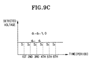
- the microcomputer 12 obtains the difference between pairs of succeeding data points and adds differences obtained from at least five turntable rotation periods.
- d n
- d n-1
- d n-2
- d n-3
- X d n + d n-1 + d n-2 + d n-3
- the microcomputer 12 recognises that defrosting is completed and terminates the defrosting operation.
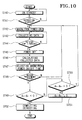
- step ST60 the microwave oven is on standby for defrosting operation and the microcomputer 12 determines whether the defrosting start key has been pressed (step ST61).
- the microcomputer 12 Upon determining that the defrosting start key has been pressed, the microcomputer 12 controls the magnetron 18 to generate microwaves for defrosting. Also, the microcomputer 12 rotates the turntable 24 at a predetermined speed (step ST62).
- the microcomputer 12 regularly receives voltage signals from the voltage detecting section 8 reporting the standing wave magnitude (step ST63).
- the microcomputer 12 determines whether a turntable rotation period corresponding to thee rotations of the turntable 24 has been completed at step ST64.
- step ST65 When the microcomputer 12 determines that a turntable rotation period has been completed, the microcomputer 12 switches off the magnetron 18 (step ST65).
- the microcomputer determines whether the turntable 24 has rotated for five turntable rotation periods (step ST66)
- the microcomputer 12 calculates the differences (d n , d n-1 , d n-2 , d n-3 ) between the detected data for the respective turntable rotation periods, and accumulates the differences (d n , d n-1 , d n-2 , d n-3 ).
- the microcomputer 12 determines whether the accumulated total of the differences (d n , d n-1 , d n-2 , d n-3 ) is less than a predetermined value ( ⁇ ) (step ST67).
- the microcomputer 12 fits a cubic curve to the detected data for a plurality of turntable rotation periods (step ST68). Then, the microcomputer 12 calculates the maximum and minimum points (t1 and t2) by differentiation of the cubic equation (step ST69).
- the microcomputer 12 determines whether the roots, i.e., the points (t1 and t2), are imaginary (step ST70). If it is determined that the roots are imaginary, the microcomputer returns to the step ST62 to repeat the steps from ST62 to ST69.
- the microcomputer 12 adds one more turntable rotation period (step ST74), and returns to step ST67 to repeat the steps from step ST67 to step ST71.
- the microcomputer 12 recognises the type and weight of the defrosting food by the time and data variations ( ⁇ t and ⁇ f(t)), and adjusts the magnetron power according to the recognised status of the defrosting food (step ST75).
- step ST67 If the result of the step ST67 indicates that the accumulated total of the differences (d n , d n-1 , d n-2 , d n-3 ) is less than the predetermined value ( ⁇ ), the microcomputer 12 recognises that defrosting is complete and accordingly terminates the defrosting operation (step ST76).
- the microcomputer calculates the data of food in the microwave oven detected by a sensor, and accordingly adjusts the level of output power of magnetron and determines the defrosting completion time. Accordingly, regardless of various frozen status, weight, or size of the food, the user can perform the defrosting operation properly with one button manipulation for executing the defrosting operation of the microwave oven.
Landscapes
- Physics & Mathematics (AREA)
- Electromagnetism (AREA)
- Engineering & Computer Science (AREA)
- Chemical & Material Sciences (AREA)
- Combustion & Propulsion (AREA)
- Mechanical Engineering (AREA)
- General Engineering & Computer Science (AREA)
- Control Of High-Frequency Heating Circuits (AREA)
- Electric Ovens (AREA)
Applications Claiming Priority (4)
| Application Number | Priority Date | Filing Date | Title |
|---|---|---|---|
| KR19990000762 | 1999-01-14 | ||
| KR9900762 | 1999-01-14 | ||
| KR9927331 | 1999-07-07 | ||
| KR19990027331 | 1999-07-07 |
Publications (3)
| Publication Number | Publication Date |
|---|---|
| EP1021068A2 true EP1021068A2 (fr) | 2000-07-19 |
| EP1021068A3 EP1021068A3 (fr) | 2003-09-17 |
| EP1021068B1 EP1021068B1 (fr) | 2007-03-21 |
Family
ID=26634582
Family Applications (1)
| Application Number | Title | Priority Date | Filing Date |
|---|---|---|---|
| EP00300261A Expired - Lifetime EP1021068B1 (fr) | 1999-01-14 | 2000-01-14 | Procédé de décongélation micro-ondes |
Country Status (7)
| Country | Link |
|---|---|
| US (1) | US6166363A (fr) |
| EP (1) | EP1021068B1 (fr) |
| JP (1) | JP3795286B2 (fr) |
| KR (1) | KR100341327B1 (fr) |
| CN (1) | CN1253676C (fr) |
| CA (1) | CA2295413C (fr) |
| DE (1) | DE60033980T2 (fr) |
Cited By (1)
| Publication number | Priority date | Publication date | Assignee | Title |
|---|---|---|---|---|
| EP1594345A1 (fr) * | 2004-04-01 | 2005-11-09 | Electrolux Schwanden AG | Four à micro-ondes |
Families Citing this family (12)
| Publication number | Priority date | Publication date | Assignee | Title |
|---|---|---|---|---|
| KR100586510B1 (ko) * | 2000-12-06 | 2006-06-07 | 삼성전자주식회사 | 전자렌지 및 그 제어방법 |
| CN100493271C (zh) * | 2002-08-02 | 2009-05-27 | 夏普株式会社 | 高频加热装置 |
| US8653482B2 (en) * | 2006-02-21 | 2014-02-18 | Goji Limited | RF controlled freezing |
| EP2061287B1 (fr) | 2007-11-15 | 2015-03-25 | Topinox Sarl | Procédé destiné au réglage de la synchronisation d'un générateur à micro-ondes pulsé d'un appareil de cuisson et appareil de cuisson correspondant |
| KR101588830B1 (ko) * | 2009-06-19 | 2016-01-26 | 엘지전자 주식회사 | 마이크로웨이브를 이용한 조리기기 |
| US9398646B2 (en) * | 2009-07-10 | 2016-07-19 | Panasonic Intellectual Property Management Co., Ltd. | Microwave heating device and microwave heating control method |
| WO2017164291A1 (fr) * | 2016-03-25 | 2017-09-28 | パナソニックIpマネジメント株式会社 | Appareil de chauffage par micro-ondes |
| CN108679663A (zh) * | 2018-05-21 | 2018-10-19 | 广东美的厨房电器制造有限公司 | 微波炉解冻控制方法、微波炉、终端及计算机存储介质 |
| US10477585B1 (en) * | 2018-07-30 | 2019-11-12 | Amazon Technologies, Inc. | Microwave interference mitigation |
| CN110933795B (zh) * | 2019-11-15 | 2022-02-25 | 广东美的厨房电器制造有限公司 | 微波炉及其控制方法、装置以及存储介质 |
| EP4110014A4 (fr) * | 2020-02-21 | 2023-08-16 | Panasonic Intellectual Property Management Co., Ltd. | Dispositif de traitement haute fréquence |
| US12120803B2 (en) * | 2020-07-13 | 2024-10-15 | Haier Us Appliance Solutions, Inc. | Cooking appliance with variable microwave and turntable timing |
Family Cites Families (12)
| Publication number | Priority date | Publication date | Assignee | Title |
|---|---|---|---|---|
| US4281022A (en) * | 1977-08-30 | 1981-07-28 | Litton Systems, Inc. | Method of cooking thin meats in a microwave oven |
| US4210795A (en) * | 1978-11-30 | 1980-07-01 | Litton Systems, Inc. | System and method for regulating power output in a microwave oven |
| US4317977A (en) * | 1979-09-06 | 1982-03-02 | Litton Systems, Inc. | Power controlled microwave oven |
| GB2117925B (en) * | 1982-02-19 | 1986-02-05 | Hitachi Heating Appl | Heating apparatus of thawing sensor controlled type |
| US4507530A (en) * | 1983-08-15 | 1985-03-26 | General Electric Company | Automatic defrost sensing arrangement for microwave oven |
| US4864088A (en) * | 1987-07-03 | 1989-09-05 | Sanyo Electric Co., Ltd. | Electronically controlled cooking apparatus for controlling heating of food using a humidity sensor |
| DE3743921A1 (de) * | 1987-12-23 | 1989-07-13 | Bosch Siemens Hausgeraete | Steueranordnung zum waermetechnischen behandeln von lebensmitteln durch mikrowellenenergie |
| JPH0395314A (ja) * | 1989-09-07 | 1991-04-19 | Matsushita Electric Ind Co Ltd | 高周波加熱装置 |
| JPH03219587A (ja) * | 1990-01-25 | 1991-09-26 | Matsushita Electric Ind Co Ltd | 高周波加熱装置 |
| US5436433A (en) * | 1993-03-19 | 1995-07-25 | Goldstar Co., Ltd. | Automatic thawing device of microwave oven and control method thereof |
| KR960008974B1 (en) * | 1993-12-30 | 1996-07-10 | Lg Electronics Inc | Auto defrosting apparatus for microwave oven |
| KR100196692B1 (ko) * | 1996-03-26 | 1999-06-15 | 구자홍 | 전자레인지의 용기의 뚜껑 유무 및 분량 인식장치와 방법 |
-
2000
- 2000-01-12 US US09/481,518 patent/US6166363A/en not_active Expired - Lifetime
- 2000-01-13 CA CA002295413A patent/CA2295413C/fr not_active Expired - Fee Related
- 2000-01-14 JP JP2000007167A patent/JP3795286B2/ja not_active Expired - Fee Related
- 2000-01-14 EP EP00300261A patent/EP1021068B1/fr not_active Expired - Lifetime
- 2000-01-14 CN CNB001002937A patent/CN1253676C/zh not_active Expired - Fee Related
- 2000-01-14 KR KR1020000001670A patent/KR100341327B1/ko not_active Expired - Fee Related
- 2000-01-14 DE DE60033980T patent/DE60033980T2/de not_active Expired - Lifetime
Cited By (2)
| Publication number | Priority date | Publication date | Assignee | Title |
|---|---|---|---|---|
| EP1594345A1 (fr) * | 2004-04-01 | 2005-11-09 | Electrolux Schwanden AG | Four à micro-ondes |
| DE102004015993B4 (de) * | 2004-04-01 | 2010-04-15 | Electrolux Schwanden Ag | Mikrowellengerät sowie Verfahren zum Betrieb eines Mikrowellengeräts |
Also Published As
| Publication number | Publication date |
|---|---|
| KR100341327B1 (ko) | 2002-06-22 |
| CN1253676C (zh) | 2006-04-26 |
| EP1021068A3 (fr) | 2003-09-17 |
| CA2295413A1 (fr) | 2000-07-14 |
| JP3795286B2 (ja) | 2006-07-12 |
| KR20000053491A (ko) | 2000-08-25 |
| JP2000220838A (ja) | 2000-08-08 |
| DE60033980T2 (de) | 2007-08-30 |
| US6166363A (en) | 2000-12-26 |
| EP1021068B1 (fr) | 2007-03-21 |
| CA2295413C (fr) | 2003-04-15 |
| CN1261144A (zh) | 2000-07-26 |
| DE60033980D1 (de) | 2007-05-03 |
Similar Documents
| Publication | Publication Date | Title |
|---|---|---|
| EP1021068B1 (fr) | Procédé de décongélation micro-ondes | |
| EP0268329B1 (fr) | Four à micro-ondes | |
| EP1069806B1 (fr) | Dégivrage dans un four à micro-ondes | |
| US4568201A (en) | Temperature measuring apparatus | |
| KR100411683B1 (ko) | 가열조리기 | |
| US6396035B2 (en) | Microwave oven and data obtaining method therefor | |
| CA1192618A (fr) | Four a micro-ondes a cuisson automatique et dispositif rechauffeur | |
| US5545881A (en) | Heating time control apparatus and method thereof for microwave oven | |
| US6166362A (en) | Automatic cooking control method for a microwave oven | |
| EP1211913B1 (fr) | Méthode de commande du dégivrage dans un four à micro-ondes | |
| KR100186390B1 (ko) | 전자레인지의 냉동식품 해동방법 | |
| JP2856679B2 (ja) | 電子レンジの飲食物解凍方法 | |
| US5422465A (en) | Apparatus for and method of automatically heating foods in microwave oven | |
| EP0763963B1 (fr) | Procédé de contrôle de cuisson dans un four à micro-ondes utilisant un détecteur de vapeur | |
| EP0928125B1 (fr) | Méthode et appareil pour compenser la température dans un four à micro-ondes | |
| EP0688149B1 (fr) | Méthode pour la régulation de l'émission de l'humidité d'un four à micro-ondes, et un four à micro-ondes avec un détecteur de régulation de l'humidité selon la méthode | |
| KR100214598B1 (ko) | 써모파일형 온도센서를 이용한 전자레인지 및 그의 자동해동방법 | |
| US5395633A (en) | Method for automatically controlling cooking of food with low moisture content | |
| AU771090B2 (en) | Defrosting method for a microwave oven | |
| US6791070B2 (en) | Simmering control method in microwave oven | |
| AU763026B2 (en) | Data obtaining method for a microwave oven | |
| JP3525254B2 (ja) | 高周波加熱装置 | |
| AU1007900A (en) | Defrosting method for a microwave oven | |
| KR100341331B1 (ko) | 전자렌지의 해동 제어방법 | |
| JPH0831568A (ja) | 高周波加熱装置 |
Legal Events
| Date | Code | Title | Description |
|---|---|---|---|
| PUAI | Public reference made under article 153(3) epc to a published international application that has entered the european phase |
Free format text: ORIGINAL CODE: 0009012 |
|
| AK | Designated contracting states |
Kind code of ref document: A2 Designated state(s): AT BE CH CY DE DK ES FI FR GB GR IE IT LI LU MC NL PT SE |
|
| AX | Request for extension of the european patent |
Free format text: AL;LT;LV;MK;RO;SI |
|
| RIN1 | Information on inventor provided before grant (corrected) |
Inventor name: LEE, WON-WOO Inventor name: SHON, JONG-CHULL Inventor name: LIM, DONG-BIN Inventor name: JANG, BO-IN |
|
| PUAL | Search report despatched |
Free format text: ORIGINAL CODE: 0009013 |
|
| AK | Designated contracting states |
Kind code of ref document: A3 Designated state(s): AT BE CH CY DE DK ES FI FR GB GR IE IT LI LU MC NL PT SE |
|
| AX | Request for extension of the european patent |
Extension state: AL LT LV MK RO SI |
|
| 17P | Request for examination filed |
Effective date: 20031103 |
|
| AKX | Designation fees paid |
Designated state(s): DE FR GB NL |
|
| RAP1 | Party data changed (applicant data changed or rights of an application transferred) |
Owner name: SAMSUNG ELECTRONICS CO., LTD. |
|
| GRAP | Despatch of communication of intention to grant a patent |
Free format text: ORIGINAL CODE: EPIDOSNIGR1 |
|
| GRAS | Grant fee paid |
Free format text: ORIGINAL CODE: EPIDOSNIGR3 |
|
| GRAA | (expected) grant |
Free format text: ORIGINAL CODE: 0009210 |
|
| AK | Designated contracting states |
Kind code of ref document: B1 Designated state(s): DE FR GB NL |
|
| REG | Reference to a national code |
Ref country code: GB Ref legal event code: FG4D |
|
| REF | Corresponds to: |
Ref document number: 60033980 Country of ref document: DE Date of ref document: 20070503 Kind code of ref document: P |
|
| ET | Fr: translation filed | ||
| PLBE | No opposition filed within time limit |
Free format text: ORIGINAL CODE: 0009261 |
|
| STAA | Information on the status of an ep patent application or granted ep patent |
Free format text: STATUS: NO OPPOSITION FILED WITHIN TIME LIMIT |
|
| 26N | No opposition filed |
Effective date: 20071227 |
|
| NLV4 | Nl: lapsed or anulled due to non-payment of the annual fee |
Effective date: 20080801 |
|
| PG25 | Lapsed in a contracting state [announced via postgrant information from national office to epo] |
Ref country code: NL Free format text: LAPSE BECAUSE OF NON-PAYMENT OF DUE FEES Effective date: 20080801 |
|
| PGFP | Annual fee paid to national office [announced via postgrant information from national office to epo] |
Ref country code: DE Payment date: 20140113 Year of fee payment: 15 |
|
| PGFP | Annual fee paid to national office [announced via postgrant information from national office to epo] |
Ref country code: FR Payment date: 20140113 Year of fee payment: 15 |
|
| PGFP | Annual fee paid to national office [announced via postgrant information from national office to epo] |
Ref country code: GB Payment date: 20140117 Year of fee payment: 15 |
|
| REG | Reference to a national code |
Ref country code: DE Ref legal event code: R119 Ref document number: 60033980 Country of ref document: DE |
|
| GBPC | Gb: european patent ceased through non-payment of renewal fee |
Effective date: 20150114 |
|
| PG25 | Lapsed in a contracting state [announced via postgrant information from national office to epo] |
Ref country code: GB Free format text: LAPSE BECAUSE OF NON-PAYMENT OF DUE FEES Effective date: 20150114 Ref country code: DE Free format text: LAPSE BECAUSE OF NON-PAYMENT OF DUE FEES Effective date: 20150801 |
|
| REG | Reference to a national code |
Ref country code: FR Ref legal event code: ST Effective date: 20150930 |
|
| PG25 | Lapsed in a contracting state [announced via postgrant information from national office to epo] |
Ref country code: FR Free format text: LAPSE BECAUSE OF NON-PAYMENT OF DUE FEES Effective date: 20150202 |