EP1022074B1 - Assemblage d' un corps à sa structure de support - Google Patents
Assemblage d' un corps à sa structure de support Download PDFInfo
- Publication number
- EP1022074B1 EP1022074B1 EP00400165A EP00400165A EP1022074B1 EP 1022074 B1 EP1022074 B1 EP 1022074B1 EP 00400165 A EP00400165 A EP 00400165A EP 00400165 A EP00400165 A EP 00400165A EP 1022074 B1 EP1022074 B1 EP 1022074B1
- Authority
- EP
- European Patent Office
- Prior art keywords
- support member
- support
- hole
- support structure
- members
- Prior art date
- Legal status (The legal status is an assumption and is not a legal conclusion. Google has not performed a legal analysis and makes no representation as to the accuracy of the status listed.)
- Expired - Lifetime
Links
- 238000007493 shaping process Methods 0.000 claims abstract description 32
- 238000000034 method Methods 0.000 claims description 22
- 239000000463 material Substances 0.000 description 12
- 238000004519 manufacturing process Methods 0.000 description 3
- 238000012986 modification Methods 0.000 description 2
- 230000004048 modification Effects 0.000 description 2
- 230000006835 compression Effects 0.000 description 1
- 238000007906 compression Methods 0.000 description 1
- 230000009977 dual effect Effects 0.000 description 1
- 239000002184 metal Substances 0.000 description 1
- 238000003801 milling Methods 0.000 description 1
- 238000010008 shearing Methods 0.000 description 1
Images



Classifications
-
- B—PERFORMING OPERATIONS; TRANSPORTING
- B23—MACHINE TOOLS; METAL-WORKING NOT OTHERWISE PROVIDED FOR
- B23P—METAL-WORKING NOT OTHERWISE PROVIDED FOR; COMBINED OPERATIONS; UNIVERSAL MACHINE TOOLS
- B23P11/00—Connecting or disconnecting metal parts or objects by metal-working techniques not otherwise provided for
-
- A—HUMAN NECESSITIES
- A47—FURNITURE; DOMESTIC ARTICLES OR APPLIANCES; COFFEE MILLS; SPICE MILLS; SUCTION CLEANERS IN GENERAL
- A47L—DOMESTIC WASHING OR CLEANING; SUCTION CLEANERS IN GENERAL
- A47L5/00—Structural features of suction cleaners
- A47L5/12—Structural features of suction cleaners with power-driven air-pumps or air-compressors, e.g. driven by motor vehicle engine vacuum
- A47L5/22—Structural features of suction cleaners with power-driven air-pumps or air-compressors, e.g. driven by motor vehicle engine vacuum with rotary fans
-
- B—PERFORMING OPERATIONS; TRANSPORTING
- B21—MECHANICAL METAL-WORKING WITHOUT ESSENTIALLY REMOVING MATERIAL; PUNCHING METAL
- B21D—WORKING OR PROCESSING OF SHEET METAL OR METAL TUBES, RODS OR PROFILES WITHOUT ESSENTIALLY REMOVING MATERIAL; PUNCHING METAL
- B21D39/00—Application of procedures in order to connect objects or parts, e.g. coating with sheet metal otherwise than by plating; Tube expanders
- B21D39/03—Application of procedures in order to connect objects or parts, e.g. coating with sheet metal otherwise than by plating; Tube expanders of sheet metal otherwise than by folding
-
- F—MECHANICAL ENGINEERING; LIGHTING; HEATING; WEAPONS; BLASTING
- F04—POSITIVE - DISPLACEMENT MACHINES FOR LIQUIDS; PUMPS FOR LIQUIDS OR ELASTIC FLUIDS
- F04D—NON-POSITIVE-DISPLACEMENT PUMPS
- F04D29/00—Details, component parts, or accessories
- F04D29/26—Rotors specially for elastic fluids
- F04D29/28—Rotors specially for elastic fluids for centrifugal or helico-centrifugal pumps for radial-flow or helico-centrifugal pumps
- F04D29/281—Rotors specially for elastic fluids for centrifugal or helico-centrifugal pumps for radial-flow or helico-centrifugal pumps for fans or blowers
- F04D29/282—Rotors specially for elastic fluids for centrifugal or helico-centrifugal pumps for radial-flow or helico-centrifugal pumps for fans or blowers the leading edge of each vane being substantially parallel to the rotation axis
-
- F—MECHANICAL ENGINEERING; LIGHTING; HEATING; WEAPONS; BLASTING
- F16—ENGINEERING ELEMENTS AND UNITS; GENERAL MEASURES FOR PRODUCING AND MAINTAINING EFFECTIVE FUNCTIONING OF MACHINES OR INSTALLATIONS; THERMAL INSULATION IN GENERAL
- F16B—DEVICES FOR FASTENING OR SECURING CONSTRUCTIONAL ELEMENTS OR MACHINE PARTS TOGETHER, e.g. NAILS, BOLTS, CIRCLIPS, CLAMPS, CLIPS OR WEDGES; JOINTS OR JOINTING
- F16B17/00—Connecting constructional elements or machine parts by a part of or on one member entering a hole in the other and involving plastic deformation
- F16B17/008—Connecting constructional elements or machine parts by a part of or on one member entering a hole in the other and involving plastic deformation of sheets or plates mutually
-
- Y—GENERAL TAGGING OF NEW TECHNOLOGICAL DEVELOPMENTS; GENERAL TAGGING OF CROSS-SECTIONAL TECHNOLOGIES SPANNING OVER SEVERAL SECTIONS OF THE IPC; TECHNICAL SUBJECTS COVERED BY FORMER USPC CROSS-REFERENCE ART COLLECTIONS [XRACs] AND DIGESTS
- Y10—TECHNICAL SUBJECTS COVERED BY FORMER USPC
- Y10T—TECHNICAL SUBJECTS COVERED BY FORMER US CLASSIFICATION
- Y10T29/00—Metal working
- Y10T29/49—Method of mechanical manufacture
- Y10T29/49316—Impeller making
- Y10T29/49329—Centrifugal blower or fan
-
- Y—GENERAL TAGGING OF NEW TECHNOLOGICAL DEVELOPMENTS; GENERAL TAGGING OF CROSS-SECTIONAL TECHNOLOGIES SPANNING OVER SEVERAL SECTIONS OF THE IPC; TECHNICAL SUBJECTS COVERED BY FORMER USPC CROSS-REFERENCE ART COLLECTIONS [XRACs] AND DIGESTS
- Y10—TECHNICAL SUBJECTS COVERED BY FORMER USPC
- Y10T—TECHNICAL SUBJECTS COVERED BY FORMER US CLASSIFICATION
- Y10T29/00—Metal working
- Y10T29/49—Method of mechanical manufacture
- Y10T29/49826—Assembling or joining
- Y10T29/49828—Progressively advancing of work assembly station or assembled portion of work
-
- Y—GENERAL TAGGING OF NEW TECHNOLOGICAL DEVELOPMENTS; GENERAL TAGGING OF CROSS-SECTIONAL TECHNOLOGIES SPANNING OVER SEVERAL SECTIONS OF THE IPC; TECHNICAL SUBJECTS COVERED BY FORMER USPC CROSS-REFERENCE ART COLLECTIONS [XRACs] AND DIGESTS
- Y10—TECHNICAL SUBJECTS COVERED BY FORMER USPC
- Y10T—TECHNICAL SUBJECTS COVERED BY FORMER US CLASSIFICATION
- Y10T29/00—Metal working
- Y10T29/49—Method of mechanical manufacture
- Y10T29/49826—Assembling or joining
- Y10T29/49833—Punching, piercing or reaming part by surface of second part
-
- Y—GENERAL TAGGING OF NEW TECHNOLOGICAL DEVELOPMENTS; GENERAL TAGGING OF CROSS-SECTIONAL TECHNOLOGIES SPANNING OVER SEVERAL SECTIONS OF THE IPC; TECHNICAL SUBJECTS COVERED BY FORMER USPC CROSS-REFERENCE ART COLLECTIONS [XRACs] AND DIGESTS
- Y10—TECHNICAL SUBJECTS COVERED BY FORMER USPC
- Y10T—TECHNICAL SUBJECTS COVERED BY FORMER US CLASSIFICATION
- Y10T29/00—Metal working
- Y10T29/49—Method of mechanical manufacture
- Y10T29/49826—Assembling or joining
- Y10T29/49833—Punching, piercing or reaming part by surface of second part
- Y10T29/49835—Punching, piercing or reaming part by surface of second part with shaping
-
- Y—GENERAL TAGGING OF NEW TECHNOLOGICAL DEVELOPMENTS; GENERAL TAGGING OF CROSS-SECTIONAL TECHNOLOGIES SPANNING OVER SEVERAL SECTIONS OF THE IPC; TECHNICAL SUBJECTS COVERED BY FORMER USPC CROSS-REFERENCE ART COLLECTIONS [XRACs] AND DIGESTS
- Y10—TECHNICAL SUBJECTS COVERED BY FORMER USPC
- Y10T—TECHNICAL SUBJECTS COVERED BY FORMER US CLASSIFICATION
- Y10T29/00—Metal working
- Y10T29/49—Method of mechanical manufacture
- Y10T29/49826—Assembling or joining
- Y10T29/49908—Joining by deforming
- Y10T29/49915—Overedge assembling of seated part
-
- Y—GENERAL TAGGING OF NEW TECHNOLOGICAL DEVELOPMENTS; GENERAL TAGGING OF CROSS-SECTIONAL TECHNOLOGIES SPANNING OVER SEVERAL SECTIONS OF THE IPC; TECHNICAL SUBJECTS COVERED BY FORMER USPC CROSS-REFERENCE ART COLLECTIONS [XRACs] AND DIGESTS
- Y10—TECHNICAL SUBJECTS COVERED BY FORMER USPC
- Y10T—TECHNICAL SUBJECTS COVERED BY FORMER US CLASSIFICATION
- Y10T29/00—Metal working
- Y10T29/49—Method of mechanical manufacture
- Y10T29/49826—Assembling or joining
- Y10T29/49908—Joining by deforming
- Y10T29/49936—Surface interlocking
-
- Y—GENERAL TAGGING OF NEW TECHNOLOGICAL DEVELOPMENTS; GENERAL TAGGING OF CROSS-SECTIONAL TECHNOLOGIES SPANNING OVER SEVERAL SECTIONS OF THE IPC; TECHNICAL SUBJECTS COVERED BY FORMER USPC CROSS-REFERENCE ART COLLECTIONS [XRACs] AND DIGESTS
- Y10—TECHNICAL SUBJECTS COVERED BY FORMER USPC
- Y10T—TECHNICAL SUBJECTS COVERED BY FORMER US CLASSIFICATION
- Y10T29/00—Metal working
- Y10T29/49—Method of mechanical manufacture
- Y10T29/49826—Assembling or joining
- Y10T29/49908—Joining by deforming
- Y10T29/49938—Radially expanding part in cavity, aperture, or hollow body
Definitions
- the present invention relates generally to support structures as indicated in the pre-characterising portion of claim 1, and more particularly to a support structure for a body such as an impeller and a method of making the same as indicated in the pre-characterising portion of claim 7, for use on a rotary shaft located in the motor of a vacuum cleaner.
- Such a support structure and method is known from JP-A-58 119 999.
- U.S. Patent No. 2,870,533 discloses a method of manufacturing a double-faced bearing washer.
- a bimetallic washer is provided.
- a dual punch advances through the washer, on one side shearing a circle completely out of the washer.
- On the other the punch advances approximately half way thereby creating a recess on one side of the washer, and a projection on the other.
- Multiple bearing washers are then stacked by inserting the projection of a first bearing into a sheared circle of a second washer. No plates are joined by the punch.
- the present invention provides a support structure and method of making the same for use on impellers that are attached to a rotary shaft in the motor of a vacuum cleaner.
- the method according to the invention requires a simple implementation, and the materials to be joined are interlocked as soon as an upper die presses the materials together.
- a support structure in combination with a body includes a first support member disposed in contact with a first side of the body and a second support member disposed in contact with a second side of the body opposite the first side.
- the support members include apertures that are aligned with an opening of the body to form a bore for receiving a shaft, and portions of the first support member and the body extend into a hole of the second support member to join the first and second support members and the body together.
- the first and second support members have diameters smaller than the diameter of the body, and thicknesses greater than the thickness of the body. Furthermore, the second support member has a plurality of additional spaced holes each for receiving additional portions of the first support member and the body.
- the second support member has a first surface in contact with the body and a second surface opposite the first surface, so that the portion of the body that extends into the hole of the second support member also extends past the second surface of the second support member.
- the second support member also has two additional spaced holes each for receiving additional portions of the first support member and the body.
- a method of assembling a support structure for body includes providing a first support member disposed in contact with a first side of the body, providing a second support member disposed in contact with a second side of the body opposite the first side, aligning apertures of the support members with an opening of the body to form a bore for receiving a shaft, and extending portions of the first support member and the body into a hole of the second support member to join the first and second support members and the body together.
- a method of securing a first support member to a second support member includes placing the second support member in a die so that a hole of the second support member is located at a predetermined position, placing the first support member adjacent to the second support member so that apertures of the support members are aligned, and advancing a shaping pin toward the first support member in alignment with the predetermined position.
- the shaping pin has a leading portion of a first diameter and a trailing portion of a second diameter greater than the first diameter, and the trailing portion is separated from the leading portion by a shoulder.
- the shoulder of the shaping pin extends into the first support member.
- the shaping pin is further advanced into the first support member until the first and second support members are joined together.
- a method of securing a body between first and second support members includes placing the second support member in a die such that a hole of the second support member is located at a predetermined position, placing the body adjacent to the second support member, placing the first support member adjacent to the body so that apertures of the support members and an opening of the body are aligned, advancing a shaping pin toward the first support member in alignment with the predetermined position so that the shoulder of the shaping pin extends into the first support member, and further advancing the shaping pin through the first support member and the body until the support members and the body are joined together.
- a method of securing a first support member to a second support member includes placing the second support member in a die so that a hole of the second support member is located at a predetermined position, placing the first support member adjacent to the second support member so that apertures of the support members are aligned, and advancing a shaping pin, which is of uniform cross sectional size along a full length thereof, toward the first support member in alignment with the predetermined position.
- a shaping pin which is of uniform cross sectional size along a full length thereof, toward the first support member in alignment with the predetermined position.
- the shaping pin is advanced, the entire shaping pin extends into the first support member.
- the shaping pin is further advanced into the first support member until the first and second members are joined together.
- a method of securing a body between first and second support members includes placing the second support member in a die such that a hole of the second support member is located at a predetermined position, placing the body adjacent to the second support member, placing the first support member adjacent to the body so that apertures of the support members and an opening of the body are aligned, advancing a shaping pin, which is of uniform cross sectional size along a full length thereof, toward the first support member in alignment with the predetermined position so that the entire shaping pin extends into the first support member, and further advancing the shaping pin through the first support member and the body until the support members and the body are joined together.
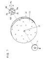
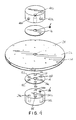
- a support structure 10 includes first and second support members 12 and 14.
- the first support member 12 includes an aperture 16.
- the second support member includes at least one, and preferably a plurality of holes 18a-18f and an aperture 20.
- the first support member 12 is disposed in contact with a first side 22 of a body in the form of an impeller 24.
- the second support member 14 is disposed in contact with a second side 26 of the impeller 24 opposite the first side 22.
- Apertures 16 and 20 of the first and second support members 12 and 14 are aligned with the opening 28 of the impeller 24 to form a bore for receiving a shaft 30.
- a die 32 contains three recesses 34a, 34b, and 34c, and locator pins 36 and 38.
- the second support member 14 is placed in the die 32 so that the locator pins 36 and 38 are disposed in the holes 18f and 18b.
- the impeller 24 is then placed atop the second support member 14 so that the opening 28 is aligned with the aperture 20.
- the first support member 12 is then placed atop the impeller 24 so that the aperture 16 is aligned with the opening 28.
- apparatus may be provided to prevent lateral shifting of the impeller 24 and the first support member 12.
- At least one, and preferably three shaping pins 40a, 40b, and 40c each having a leading portion 42 and a trailing portion 44 of a greater diameter is advanced toward the first support member 12 in alignment with the holes 18a, 18c and 18e of the second support member 14.
- Each leading portion 42 is separated from an associated trailing portion 44 by a shoulder 46.
- the shaping pins 40a-40c are replaced by the shaping pins 41a-41c which could be of uniform cross sectional size along a full length thereof, without a leading portion 42 and trailing portion 44 separated by a shoulder 46.
- each shaping pin 40a-40c As each shaping pin 40a-40c is advanced toward the first support member 12, the entire shoulder 46 of each shaping pin 40a-40c extends into the first support member 12, pushing the material of the first support member 12 and the material of the impeller 24 through the holes 18a, 18c and 18e of the second support member 14.
- the shaping pins 40a-40c continue to advance through the first support member 12 and the impeller 24 until a portion of the impeller 24 is displaced past a surface 48 of the second support member 14 into respective recesses 34a-34c in the die 32. Once the shaping pins 40a-40c press the support members 12 and 14 and the impeller 24 together, the materials are interlocked and the support structure is formed. If desired, the portions of the impeller 24 that extend past the surface 48 of the second support member 14 can be removed by milling or any other suitable process if a flat surface is desired.
- the holes 18a, 18c and 18e are equally angularly spaced, as are the shaping pins 40a-40c, so that a good mechanical interconnection is obtained.
- a different number of holes 18 could alternatively be provided as could a different number of shaping pins 40.
Landscapes
- Engineering & Computer Science (AREA)
- Mechanical Engineering (AREA)
- General Engineering & Computer Science (AREA)
- Turbine Rotor Nozzle Sealing (AREA)
- Structures Of Non-Positive Displacement Pumps (AREA)
- Lining Or Joining Of Plastics Or The Like (AREA)
- Conveying And Assembling Of Building Elements In Situ (AREA)
- Mutual Connection Of Rods And Tubes (AREA)
- Joining Of Building Structures In Genera (AREA)
- Connection Of Plates (AREA)
- Casting Or Compression Moulding Of Plastics Or The Like (AREA)
Claims (11)
- Structure de support (10) en combinaison avec un corps (24), ledit corps (24) ayant une ouverture (28), comprenant :dans laquelle les éléments de support (12, 14) incluent des ouvertures (16, 20) alignées avec l'ouverture (28) du corps (24) pour former un perçage recevant une tige (30) à l'intérieur ;un premier élément de support (12) disposé en contact avec un premier côté (22) du corps (24),un second élément de support (14) ayant un trou (18a), ledit second élément de support (14) étant disposé en contact avec un second côté (26) du corps (24) opposé au premier côté (22) ;
caractérisée en ce que
des parties du premier élément de support (12) et du corps (24) s'étendent dans un trou (18a) du second élément de support (14) pour joindre le premier et le second élément de support ainsi que le corps ensemble. - Structure de support (10) selon la revendication 1, dans laquelle le premier et le second élément de support (12, 14) ont chacun un diamètre plus petit qu'un diamètre du corps (24).
- Structure de support (10) selon la revendication 1, dans laquelle le premier et le second élément de support (12, 14) ont chacun une épaisseur supérieure à une épaisseur du corps (24).
- Structure de support (10) selon la revendication 1, dans laquelle le second élément de support (14) a une pluralité de trous additionnels (18d, 18, ...) également espacés, chacun pour recevoir des parties additionnelles du premier élément de support (12) et du corps (24).
- Structure de support (10) selon la revendication 1, dans laquelle le second élément de support (14) a une première surface en contact avec le corps (24) et une seconde surface opposée à la première surface, et
dans laquelle la partie du corps (24) qui s'étend dans le trou (20) du second élément de support (14) s'étend au-delà de la seconde surface du second élément de support (14). - Structure de support (10) selon la revendication 4, dans laquelle le second élément de support (14) a deux trous additionnels (18b, 18c) et
dans laquelle le premier trou précité (18a) et les deux trous additionnels (18b, 18c) sont également espacés pour recevoir des parties additionnelles du premier élément de support (12) et du corps (24). - Procédé d'assemblage d'une structure de support (10) pour un corps (24), le procédé comprenant les opérations consistant à :ledit procédé étant caractérisé par l'opération consistant àprocurer un premier élément de support (12) disposé en contact avec un premier côté (22) du corps (24) ;procurer un second élément de support (14) ayant un trou (18a), ledit second élément de support (14) étant disposé en contact avec un second côté (26) du corps (24) opposé au premier côté ;aligner des ouvertures (16, 20) des éléments de support (12, 14) avec une ouverture (28) du corps (24) pour former un perçage afin de recevoir une tige (30) à l'intérieur ;amener des parties du premier élément de support (12) et du corps (24) à s'étendre dans un trou (18a) du second élément de support (14) pour joindre le premier et le second élément de support (12, 14) ainsi que le corps (24) ensemble.
- Procédé d'assemblage d'une structure de support (10) selon la revendication 7, comprenant en outre l'opération consistant à amener la partie du corps (24) qui s'étend dans le trou (18a) du second élément de support (14) à s'étendre au-delà d'une seconde surface du second élément de support (14) opposée à une première surface qui est en contact avec le corps (24).
- Procédé d'assemblage d'une structure de support (10) selon la revendication 8, comprenant en outre l'opération consistant à enlever la partie du corps (24) qui s'étend au-delà de la seconde surface du second élément de support (14).
- Procédé selon la revendication 7, dans lequel les parties du premier élément de support (17) et du corps (24) sont amenées à s'étendre dans un trou (18a) du second élément de support (14) en faisant avancer une tige de mise en forme (40a) ayant une partie de tête (42) d'un premier diamètre et une partie de queue (44) d'un second diamètre supérieur au premier diamètre, ladite partie de queue (44) étant séparée de la partie de tête (42) par un épaulement (46).
- Procédé selon la revendication 7, dans lequel les parties du premier élément de support (12) et du corps (24) sont amenées à s'étendre dans un trou (18a) du second élément de support (14) en faisant avancer une tige de mise en forme (4 1a) dont la section transversale est uniforme le long de la totalité de sa longueur.
Applications Claiming Priority (2)
| Application Number | Priority Date | Filing Date | Title |
|---|---|---|---|
| US09/235,093 US6343773B1 (en) | 1999-01-21 | 1999-01-21 | Support structure |
| US235093 | 1999-01-21 |
Publications (3)
| Publication Number | Publication Date |
|---|---|
| EP1022074A2 EP1022074A2 (fr) | 2000-07-26 |
| EP1022074A3 EP1022074A3 (fr) | 2001-04-25 |
| EP1022074B1 true EP1022074B1 (fr) | 2003-09-24 |
Family
ID=22884079
Family Applications (1)
| Application Number | Title | Priority Date | Filing Date |
|---|---|---|---|
| EP00400165A Expired - Lifetime EP1022074B1 (fr) | 1999-01-21 | 2000-01-21 | Assemblage d' un corps à sa structure de support |
Country Status (5)
| Country | Link |
|---|---|
| US (2) | US6343773B1 (fr) |
| EP (1) | EP1022074B1 (fr) |
| AT (1) | ATE250475T1 (fr) |
| CA (1) | CA2296636C (fr) |
| DE (1) | DE60005410T2 (fr) |
Families Citing this family (9)
| Publication number | Priority date | Publication date | Assignee | Title |
|---|---|---|---|---|
| US6851173B2 (en) * | 2002-08-27 | 2005-02-08 | Datech Technology Co., Ltd. | Method for joining metal component by press-fit connection |
| US20060236536A1 (en) * | 2005-03-28 | 2006-10-26 | Seiko Epson Corporation | Die apparatus, method for producing perforated work plate, perforated work plate, liquid-jet head and liquid-jet apparatus |
| US7739780B2 (en) * | 2005-06-09 | 2010-06-22 | Hansen Corporation | Method of manufacturing using a die to produce a machined part |
| DE102005029525A1 (de) * | 2005-06-25 | 2006-12-28 | Zf Friedrichshafen Ag | Verbindung zwischen einem Blechteil und einer Welle, insbesondere bei einem Getriebe eines Kraftfahrzeugs |
| USD562669S1 (en) * | 2007-02-01 | 2008-02-26 | Nathan Kipperman | Hinge for adjustable furniture |
| DE102007049149A1 (de) * | 2007-10-12 | 2009-04-16 | Robert Bosch Gmbh | Verfahren zum Verbinden von Teilen eines mehrteiligen Rotorträgers und Rotorträger einer elektrischen Maschine |
| JP5313491B2 (ja) * | 2007-12-18 | 2013-10-09 | シロキ工業株式会社 | 2部材の結合方法、結合装置及び結合構造 |
| EP3088018A1 (fr) * | 2015-04-30 | 2016-11-02 | ECP Entwicklungsgesellschaft mbH | Rotor pour une pompe à fluide et procédé et moule pour sa fabrication |
| JP7241376B2 (ja) * | 2017-10-04 | 2023-03-17 | フルタ電機株式会社 | 主板とボスとの組立て方法 |
Family Cites Families (34)
| Publication number | Priority date | Publication date | Assignee | Title |
|---|---|---|---|---|
| US1571735A (en) | 1926-02-02 | Impeller | ||
| US1734541A (en) | 1925-03-12 | 1929-11-05 | Winslow Boiler & Engineering C | Process of making fans |
| US1784256A (en) * | 1928-10-12 | 1930-12-09 | Harold E Stout | Method of manufacturing sinkers for knitting machines |
| US2165808A (en) | 1937-05-22 | 1939-07-11 | Murphy Daniel | Pump rotor |
| US2254558A (en) | 1938-10-10 | 1941-09-02 | Ivan A Williams | Fastening element and method of making same |
| US2481541A (en) | 1944-06-07 | 1949-09-13 | Schneider Brothers Company | Bladed wheel |
| US2628419A (en) | 1946-11-22 | 1953-02-17 | Lau Blower Co | Blower |
| US2697873A (en) * | 1949-07-08 | 1954-12-28 | Jr James N Cooke | Elimination of squeaks in fabricated metal products |
| US2713197A (en) * | 1952-01-23 | 1955-07-19 | Budd Co | Method and apparatus for making an integral rivet connection |
| US2767906A (en) | 1952-11-07 | 1956-10-23 | Doyle Vacuum Cleaner Co | Centrifugal fan wheel |
| US2870533A (en) | 1954-01-11 | 1959-01-27 | Vandervell Products Ltd | Joining together of metal parts |
| US3225422A (en) | 1962-03-09 | 1965-12-28 | Ametek Inc | Method of fabricating centrifugal fan impellers |
| US3144204A (en) | 1962-08-24 | 1964-08-11 | Acme Engineering And Mfg Corp | Centrifugal blower wheel |
| US3224078A (en) | 1963-09-30 | 1965-12-21 | Ruth D Mayne | Method of making a turbine type blower wheel |
| US3368744A (en) | 1967-03-08 | 1968-02-13 | Jenn Air Corp | Ventilator fan impeller |
| US3557441A (en) * | 1968-01-05 | 1971-01-26 | Continental Can Co | Method of forming single operation rivet |
| DE2014250A1 (de) | 1969-04-02 | 1970-10-08 | The National Cash Register Company, Dayton, Ohio (V.St.A.) | Verfahren und Gerät zum festen Verbinden von Metallplatten |
| SE408329B (sv) * | 1976-05-12 | 1979-06-05 | Wallman Knut Olof Lennart | Flikforband for att fast forbinda platstycken med varandra och sett att utfora sadant flikforband |
| US4130922A (en) | 1977-11-07 | 1978-12-26 | Akh Inc. | Headless riveting system |
| US4174559A (en) | 1978-02-09 | 1979-11-20 | J.J. & M. | Fastening method |
| JPS58119999A (ja) | 1982-01-13 | 1983-07-16 | Hitachi Ltd | フアン用羽根車の主板またはハブとボスとの固着構造および固着構造の生産方法 |
| US4450615A (en) * | 1982-06-07 | 1984-05-29 | Pickios Anthony G | Method of fabricating a hand calculator |
| DE8408795U1 (de) * | 1984-03-22 | 1985-07-18 | Walter Eckold GmbH & Co KG Vorrichtungs- und Gerätebau, 3424 St Andreasberg | Vorrichtung zum Verbinden eines Blechs mit einem perforierten Blech |
| US4752993A (en) * | 1985-07-22 | 1988-06-28 | Oaks Daniel V | Fastener and method of attachment to sheet material |
| EP0215449B1 (fr) | 1985-09-14 | 1991-05-22 | RAPP, Eugen | Procédé et dispositif pour assembler des plaques minces |
| US4688960A (en) * | 1986-06-30 | 1987-08-25 | Chrysler Motors Corporation | Self-clinching plate fastening arrangement |
| US4978270A (en) | 1987-07-31 | 1990-12-18 | Akh, Inc. | Headless rivet |
| US4878284A (en) | 1987-12-31 | 1989-11-07 | Btm Corporation | Hand held sheet metal joining system |
| US5305517A (en) * | 1991-09-23 | 1994-04-26 | Schleicher Louis C | Apparatus for forming clinch joints |
| US5984563A (en) * | 1994-07-22 | 1999-11-16 | Btm Corporation | Apparatus for joining sheet material and joint formed therein |
| KR0128398Y1 (ko) * | 1995-07-31 | 1998-11-16 | 구자홍 | 모니터의 경사 및 회전 각도 조절장치 |
| US5720144A (en) * | 1996-03-07 | 1998-02-24 | Knudson; Gary A. | Metal beams with thermal break and methods |
| US5779309A (en) * | 1997-09-02 | 1998-07-14 | Lu; Cheng-Ho | Swivel plate device |
| US5953809A (en) * | 1997-09-25 | 1999-09-21 | Trim Trends, Inc. | Method of joining glass run channels to brackets |
-
1999
- 1999-01-21 US US09/235,093 patent/US6343773B1/en not_active Expired - Lifetime
-
2000
- 2000-01-20 CA CA002296636A patent/CA2296636C/fr not_active Expired - Fee Related
- 2000-01-21 DE DE60005410T patent/DE60005410T2/de not_active Expired - Lifetime
- 2000-01-21 EP EP00400165A patent/EP1022074B1/fr not_active Expired - Lifetime
- 2000-01-21 AT AT00400165T patent/ATE250475T1/de not_active IP Right Cessation
-
2001
- 2001-11-01 US US10/002,078 patent/US6539605B2/en not_active Expired - Lifetime
Also Published As
| Publication number | Publication date |
|---|---|
| EP1022074A3 (fr) | 2001-04-25 |
| US6539605B2 (en) | 2003-04-01 |
| ATE250475T1 (de) | 2003-10-15 |
| CA2296636C (fr) | 2007-05-01 |
| CA2296636A1 (fr) | 2000-07-21 |
| EP1022074A2 (fr) | 2000-07-26 |
| DE60005410T2 (de) | 2004-07-01 |
| US20020046455A1 (en) | 2002-04-25 |
| US6343773B1 (en) | 2002-02-05 |
| DE60005410D1 (de) | 2003-10-30 |
Similar Documents
| Publication | Publication Date | Title |
|---|---|---|
| EP1022074B1 (fr) | Assemblage d' un corps à sa structure de support | |
| JP5286433B2 (ja) | リベット | |
| US5548486A (en) | Pinned module | |
| CN103765020B (zh) | 小型平头销 | |
| GB2125321A (en) | Improvements in or relating to methods of manufacturing stacked lamination assemblies for armatures of electric machines | |
| US7485059B2 (en) | Two piece stamped steel pulley | |
| US6527490B1 (en) | Punching, stamping rivet | |
| JP2583201B2 (ja) | 金属板間の接合構造 | |
| MXPA00004811A (es) | Piezas laminadas y metodo para elaborar las mismas. | |
| JP5053990B2 (ja) | 金属薄板からなる積層体、および薄板積層体を形成するためのプロセス | |
| KR20070116089A (ko) | 시트 재료 굽힘선 변위 툴링 및 방법 | |
| US6158266A (en) | Process for manufacturing a mounting plate | |
| US20060039778A1 (en) | Stamped rivet | |
| JP3384606B2 (ja) | 金属製板材の接合構造及び接合方法 | |
| JPS58193934A (ja) | 連結素子 | |
| US20060123619A1 (en) | Strike and method of forming same | |
| MXPA00000780A (en) | Support structure | |
| JP2006166500A (ja) | 積層鉄心及びその製造方法 | |
| WO2002018801A1 (fr) | Procede et appareil pour jonctions | |
| JP2000329214A (ja) | 組立カムシャフトおよびその製造方法 | |
| JP7156677B2 (ja) | 積層板材構造体の製造方法 | |
| WO2008074964A1 (fr) | Procédé d'assemblage de pièces métalliques | |
| WO2005046992A1 (fr) | Appareil a matrice d'estampage progressive et procede pour la fabrication d'une pile de stratifie | |
| JP3076508U (ja) | 積層板用接合金具 | |
| JPH0562241B2 (fr) |
Legal Events
| Date | Code | Title | Description |
|---|---|---|---|
| PUAI | Public reference made under article 153(3) epc to a published international application that has entered the european phase |
Free format text: ORIGINAL CODE: 0009012 |
|
| AK | Designated contracting states |
Kind code of ref document: A2 Designated state(s): AT BE CH CY DE DK ES FI FR GB GR IE IT LI LU MC NL PT SE |
|
| AX | Request for extension of the european patent |
Free format text: AL;LT;LV;MK;RO;SI |
|
| PUAL | Search report despatched |
Free format text: ORIGINAL CODE: 0009013 |
|
| AK | Designated contracting states |
Kind code of ref document: A3 Designated state(s): AT BE CH CY DE DK ES FI FR GB GR IE IT LI LU MC NL PT SE |
|
| AX | Request for extension of the european patent |
Free format text: AL;LT;LV;MK;RO;SI |
|
| 17P | Request for examination filed |
Effective date: 20011010 |
|
| AKX | Designation fees paid |
Free format text: AT BE CH CY DE DK ES FI FR GB GR IE IT LI LU MC NL PT SE |
|
| 17Q | First examination report despatched |
Effective date: 20020607 |
|
| GRAH | Despatch of communication of intention to grant a patent |
Free format text: ORIGINAL CODE: EPIDOS IGRA |
|
| GRAH | Despatch of communication of intention to grant a patent |
Free format text: ORIGINAL CODE: EPIDOS IGRA |
|
| GRAA | (expected) grant |
Free format text: ORIGINAL CODE: 0009210 |
|
| AK | Designated contracting states |
Kind code of ref document: B1 Designated state(s): AT BE CH CY DE DK ES FI FR GB GR IE IT LI LU MC NL PT SE |
|
| PG25 | Lapsed in a contracting state [announced via postgrant information from national office to epo] |
Ref country code: CH Free format text: LAPSE BECAUSE OF FAILURE TO SUBMIT A TRANSLATION OF THE DESCRIPTION OR TO PAY THE FEE WITHIN THE PRESCRIBED TIME-LIMIT Effective date: 20030924 Ref country code: AT Free format text: LAPSE BECAUSE OF FAILURE TO SUBMIT A TRANSLATION OF THE DESCRIPTION OR TO PAY THE FEE WITHIN THE PRESCRIBED TIME-LIMIT Effective date: 20030924 Ref country code: LI Free format text: LAPSE BECAUSE OF FAILURE TO SUBMIT A TRANSLATION OF THE DESCRIPTION OR TO PAY THE FEE WITHIN THE PRESCRIBED TIME-LIMIT Effective date: 20030924 Ref country code: BE Free format text: LAPSE BECAUSE OF FAILURE TO SUBMIT A TRANSLATION OF THE DESCRIPTION OR TO PAY THE FEE WITHIN THE PRESCRIBED TIME-LIMIT Effective date: 20030924 Ref country code: FI Free format text: LAPSE BECAUSE OF FAILURE TO SUBMIT A TRANSLATION OF THE DESCRIPTION OR TO PAY THE FEE WITHIN THE PRESCRIBED TIME-LIMIT Effective date: 20030924 Ref country code: CY Free format text: LAPSE BECAUSE OF FAILURE TO SUBMIT A TRANSLATION OF THE DESCRIPTION OR TO PAY THE FEE WITHIN THE PRESCRIBED TIME-LIMIT Effective date: 20030924 |
|
| REG | Reference to a national code |
Ref country code: GB Ref legal event code: FG4D |
|
| REG | Reference to a national code |
Ref country code: CH Ref legal event code: EP |
|
| REG | Reference to a national code |
Ref country code: IE Ref legal event code: FG4D |
|
| REF | Corresponds to: |
Ref document number: 60005410 Country of ref document: DE Date of ref document: 20031030 Kind code of ref document: P |
|
| PG25 | Lapsed in a contracting state [announced via postgrant information from national office to epo] |
Ref country code: GR Free format text: LAPSE BECAUSE OF FAILURE TO SUBMIT A TRANSLATION OF THE DESCRIPTION OR TO PAY THE FEE WITHIN THE PRESCRIBED TIME-LIMIT Effective date: 20031224 Ref country code: DK Free format text: LAPSE BECAUSE OF FAILURE TO SUBMIT A TRANSLATION OF THE DESCRIPTION OR TO PAY THE FEE WITHIN THE PRESCRIBED TIME-LIMIT Effective date: 20031224 |
|
| PG25 | Lapsed in a contracting state [announced via postgrant information from national office to epo] |
Ref country code: ES Free format text: LAPSE BECAUSE OF FAILURE TO SUBMIT A TRANSLATION OF THE DESCRIPTION OR TO PAY THE FEE WITHIN THE PRESCRIBED TIME-LIMIT Effective date: 20040104 |
|
| REG | Reference to a national code |
Ref country code: SE Ref legal event code: TRGR |
|
| PG25 | Lapsed in a contracting state [announced via postgrant information from national office to epo] |
Ref country code: LU Free format text: LAPSE BECAUSE OF NON-PAYMENT OF DUE FEES Effective date: 20040121 |
|
| PG25 | Lapsed in a contracting state [announced via postgrant information from national office to epo] |
Ref country code: MC Free format text: LAPSE BECAUSE OF NON-PAYMENT OF DUE FEES Effective date: 20040131 |
|
| REG | Reference to a national code |
Ref country code: CH Ref legal event code: PL |
|
| ET | Fr: translation filed | ||
| PLBE | No opposition filed within time limit |
Free format text: ORIGINAL CODE: 0009261 |
|
| STAA | Information on the status of an ep patent application or granted ep patent |
Free format text: STATUS: NO OPPOSITION FILED WITHIN TIME LIMIT |
|
| 26N | No opposition filed |
Effective date: 20040625 |
|
| PG25 | Lapsed in a contracting state [announced via postgrant information from national office to epo] |
Ref country code: PT Free format text: LAPSE BECAUSE OF NON-PAYMENT OF DUE FEES Effective date: 20040224 |
|
| PGFP | Annual fee paid to national office [announced via postgrant information from national office to epo] |
Ref country code: IE Payment date: 20110112 Year of fee payment: 12 |
|
| PGFP | Annual fee paid to national office [announced via postgrant information from national office to epo] |
Ref country code: NL Payment date: 20110117 Year of fee payment: 12 Ref country code: SE Payment date: 20110111 Year of fee payment: 12 |
|
| REG | Reference to a national code |
Ref country code: NL Ref legal event code: V1 Effective date: 20120801 |
|
| REG | Reference to a national code |
Ref country code: SE Ref legal event code: EUG |
|
| REG | Reference to a national code |
Ref country code: IE Ref legal event code: MM4A |
|
| PG25 | Lapsed in a contracting state [announced via postgrant information from national office to epo] |
Ref country code: SE Free format text: LAPSE BECAUSE OF NON-PAYMENT OF DUE FEES Effective date: 20120122 |
|
| PG25 | Lapsed in a contracting state [announced via postgrant information from national office to epo] |
Ref country code: IE Free format text: LAPSE BECAUSE OF NON-PAYMENT OF DUE FEES Effective date: 20120121 Ref country code: NL Free format text: LAPSE BECAUSE OF NON-PAYMENT OF DUE FEES Effective date: 20120801 |
|
| REG | Reference to a national code |
Ref country code: FR Ref legal event code: PLFP Year of fee payment: 16 |
|
| REG | Reference to a national code |
Ref country code: FR Ref legal event code: PLFP Year of fee payment: 17 |
|
| REG | Reference to a national code |
Ref country code: FR Ref legal event code: PLFP Year of fee payment: 18 |
|
| PGFP | Annual fee paid to national office [announced via postgrant information from national office to epo] |
Ref country code: FR Payment date: 20161215 Year of fee payment: 18 |
|
| PGFP | Annual fee paid to national office [announced via postgrant information from national office to epo] |
Ref country code: DE Payment date: 20170117 Year of fee payment: 18 |
|
| PGFP | Annual fee paid to national office [announced via postgrant information from national office to epo] |
Ref country code: GB Payment date: 20170118 Year of fee payment: 18 |
|
| PGFP | Annual fee paid to national office [announced via postgrant information from national office to epo] |
Ref country code: IT Payment date: 20170123 Year of fee payment: 18 |
|
| REG | Reference to a national code |
Ref country code: DE Ref legal event code: R119 Ref document number: 60005410 Country of ref document: DE |
|
| GBPC | Gb: european patent ceased through non-payment of renewal fee |
Effective date: 20180121 |
|
| PG25 | Lapsed in a contracting state [announced via postgrant information from national office to epo] |
Ref country code: DE Free format text: LAPSE BECAUSE OF NON-PAYMENT OF DUE FEES Effective date: 20180801 Ref country code: FR Free format text: LAPSE BECAUSE OF NON-PAYMENT OF DUE FEES Effective date: 20180131 |
|
| REG | Reference to a national code |
Ref country code: FR Ref legal event code: ST Effective date: 20180928 |
|
| PG25 | Lapsed in a contracting state [announced via postgrant information from national office to epo] |
Ref country code: GB Free format text: LAPSE BECAUSE OF NON-PAYMENT OF DUE FEES Effective date: 20180121 |
|
| PG25 | Lapsed in a contracting state [announced via postgrant information from national office to epo] |
Ref country code: IT Free format text: LAPSE BECAUSE OF NON-PAYMENT OF DUE FEES Effective date: 20180121 |