EP1022075A2 - Dispositif pour usiner une pièce avec un outil - Google Patents
Dispositif pour usiner une pièce avec un outil Download PDFInfo
- Publication number
- EP1022075A2 EP1022075A2 EP00101160A EP00101160A EP1022075A2 EP 1022075 A2 EP1022075 A2 EP 1022075A2 EP 00101160 A EP00101160 A EP 00101160A EP 00101160 A EP00101160 A EP 00101160A EP 1022075 A2 EP1022075 A2 EP 1022075A2
- Authority
- EP
- European Patent Office
- Prior art keywords
- tool
- spindle
- pin
- projection
- recess
- Prior art date
- Legal status (The legal status is an assumption and is not a legal conclusion. Google has not performed a legal analysis and makes no representation as to the accuracy of the status listed.)
- Granted
Links
Images


Classifications
-
- B—PERFORMING OPERATIONS; TRANSPORTING
- B23—MACHINE TOOLS; METAL-WORKING NOT OTHERWISE PROVIDED FOR
- B23B—TURNING; BORING
- B23B31/00—Chucks; Expansion mandrels; Adaptations thereof for remote control
- B23B31/008—Chucks; Expansion mandrels; Adaptations thereof for remote control with arrangements for transmitting torque
-
- B—PERFORMING OPERATIONS; TRANSPORTING
- B21—MECHANICAL METAL-WORKING WITHOUT ESSENTIALLY REMOVING MATERIAL; PUNCHING METAL
- B21H—MAKING PARTICULAR METAL OBJECTS BY ROLLING, e.g. SCREWS, WHEELS, RINGS, BARRELS, BALLS
- B21H3/00—Making helical bodies or bodies having parts of helical shape
- B21H3/02—Making helical bodies or bodies having parts of helical shape external screw-threads ; Making dies for thread rolling
- B21H3/04—Making by means of profiled-rolls or die rolls
-
- B—PERFORMING OPERATIONS; TRANSPORTING
- B21—MECHANICAL METAL-WORKING WITHOUT ESSENTIALLY REMOVING MATERIAL; PUNCHING METAL
- B21B—ROLLING OF METAL
- B21B27/00—Rolls, roll alloys or roll fabrication; Lubricating, cooling or heating rolls while in use
- B21B27/02—Shape or construction of rolls
- B21B27/03—Sleeved rolls
-
- B—PERFORMING OPERATIONS; TRANSPORTING
- B21—MECHANICAL METAL-WORKING WITHOUT ESSENTIALLY REMOVING MATERIAL; PUNCHING METAL
- B21H—MAKING PARTICULAR METAL OBJECTS BY ROLLING, e.g. SCREWS, WHEELS, RINGS, BARRELS, BALLS
- B21H5/00—Making gear wheels, racks, spline shafts or worms
- B21H5/02—Making gear wheels, racks, spline shafts or worms with cylindrical outline, e.g. by means of die rolls
Definitions
- the invention relates to a device for processing a workpiece with a tool, in particular with a roller, on a spindle, on which the tool is positively placed.
- such tools are placed on the spindle pushed on and normal from the front by pressure (Screwed) tensioned and then into the device used.
- Tested around the tools to some extent Being able to put on the spindle are usually as positive connection grooves provided in one part, which strips engage in the other part. It is understandable that such a form-fitting Connection still has a certain tolerance, so the tool can be placed on the spindle at all can. During the operation of the tool, this settles Tool within this tolerance of the positive Connection to, for example, a flank of a keyway, making it an albeit minor adjustment of the tool is coming.
- the present invention is based on the object to eliminate this disadvantage and especially the tool on the spindle absolutely turning test.
- At least one of the tools should Protrude abutment on which an approximately tangential aligned pressure can be applied.
- This cylinder pin engages in a bore Spring washer, which next to the tool on the spindle is put on.
- This hole has a larger one Diameter than the diameter of the cylindrical pin, so that this cylinder pin guided with play in the hole is.
- the dowel pin is intended only as one embodiment one way to be mentioned as a print in Circumferential direction can be exerted on the tool.
- a thrust washer turned on, each with a head start in one corresponding recess in the tool or in the Spring washer engages.
- the recess in the Spring washer be larger than the projection, so that the Protrude into this recess when under pressure is set, can move. This turns the Thrust washer and transmits this rotation to the tool, which is also rotated on the spindle.
- the pressure can also be used here for the sake of simplicity appropriate grub screw. Of course can the pressure in this embodiment, as in other conceivable technical possibilities through a corresponding hydraulic or pneumatic device be applied.
- such is Bracing is provided on both sides of the tool so that it also not to an undesired tilting or tilting of the Tool can come.
- Protection is also common for an editing process a workpiece with a tool, in particular with a roller, on a spindle, where the Tool is positively placed on the spindle and a pressure in the circumferential direction on the spindle Spindle is exposed.
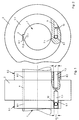
- a spindle 1 in Figure 1 recognize on which a tool 2, for example a Roll roller is placed.
- a tool 2 for example a Roll roller is placed.
- the positive connection a key 3 is used between spindle 1 and roller 2, which engages in a groove 4 in the roller 2.
- the rolling roller 2 with the spindle 1 is relative non-rotatably connected.
- the tension discs 5.1 and 5.2 point also grooves 6.1 and 6.2, in which the key 3 the spindle 1 engages.
- cylindrical rollers 7.1 and 7.2 protrude from the roller 2 on both sides, which engage in bores 8.1 and 8.2 in the clamping disks 5.1 and 5.2.
- a diameter d 1 of the bore 8.1 or 8.2 is chosen larger than a diameter d 2 of the cylindrical pins 7.1 or 7.2.
- a pressure plate 12 is used in a further embodiment of the invention according to Figures 3 to 6 .
- This Thrust washer 12 has on their opposite Surfaces each have a projection 13.1 or 13.2, which in the present embodiment as a key or wedge is trained.
- a projection 13.1 or 13.2 which in the present embodiment as a key or wedge is trained.
Landscapes
- Engineering & Computer Science (AREA)
- Mechanical Engineering (AREA)
- Gripping On Spindles (AREA)
- Jigs For Machine Tools (AREA)
- Turning (AREA)
Applications Claiming Priority (2)
| Application Number | Priority Date | Filing Date | Title |
|---|---|---|---|
| DE29901224U DE29901224U1 (de) | 1999-01-25 | 1999-01-25 | Vorrichtung zum Bearbeiten eines Werkstückes mit einem Werkzeug |
| DE29901224U | 1999-01-25 |
Publications (3)
| Publication Number | Publication Date |
|---|---|
| EP1022075A2 true EP1022075A2 (fr) | 2000-07-26 |
| EP1022075A3 EP1022075A3 (fr) | 2003-01-02 |
| EP1022075B1 EP1022075B1 (fr) | 2005-03-30 |
Family
ID=8068431
Family Applications (1)
| Application Number | Title | Priority Date | Filing Date |
|---|---|---|---|
| EP00101160A Expired - Lifetime EP1022075B1 (fr) | 1999-01-25 | 2000-01-21 | Dispositif pour usiner une pièce avec un outil |
Country Status (3)
| Country | Link |
|---|---|
| EP (1) | EP1022075B1 (fr) |
| DE (2) | DE29901224U1 (fr) |
| ES (1) | ES2235690T3 (fr) |
Cited By (1)
| Publication number | Priority date | Publication date | Assignee | Title |
|---|---|---|---|---|
| DE10119320B4 (de) * | 2001-04-19 | 2007-12-13 | Psi Production Supplier International Gmbh | Verfahren zur Herstellung von Transportrollen und Spannvorrichtung zur Durchführung des Verfahrens |
Families Citing this family (1)
| Publication number | Priority date | Publication date | Assignee | Title |
|---|---|---|---|---|
| DE102007022441B4 (de) * | 2007-05-10 | 2009-02-12 | Lenord, Bauer & Co. Gmbh | Befestigungsring |
Family Cites Families (3)
| Publication number | Priority date | Publication date | Assignee | Title |
|---|---|---|---|---|
| US1392363A (en) * | 1920-01-24 | 1921-10-04 | Edwing P Shannon | Clamping means for rotary members |
| US3013827A (en) * | 1959-04-23 | 1961-12-19 | Samuel M Langston Co | Device for clamping a part by friction to a shaft |
| DE1752342A1 (de) * | 1968-05-11 | 1971-05-19 | Pee Wee Maschinen U Appbau Wer | Rollenaufnahme fuer Rollwerkzeuge und Rollspindeln an Gewinderollmaschinen |
-
1999
- 1999-01-25 DE DE29901224U patent/DE29901224U1/de not_active Expired - Lifetime
-
2000
- 2000-01-21 ES ES00101160T patent/ES2235690T3/es not_active Expired - Lifetime
- 2000-01-21 EP EP00101160A patent/EP1022075B1/fr not_active Expired - Lifetime
- 2000-01-21 DE DE50009888T patent/DE50009888D1/de not_active Expired - Lifetime
Cited By (1)
| Publication number | Priority date | Publication date | Assignee | Title |
|---|---|---|---|---|
| DE10119320B4 (de) * | 2001-04-19 | 2007-12-13 | Psi Production Supplier International Gmbh | Verfahren zur Herstellung von Transportrollen und Spannvorrichtung zur Durchführung des Verfahrens |
Also Published As
| Publication number | Publication date |
|---|---|
| ES2235690T3 (es) | 2005-07-16 |
| EP1022075B1 (fr) | 2005-03-30 |
| DE50009888D1 (de) | 2005-05-04 |
| EP1022075A3 (fr) | 2003-01-02 |
| DE29901224U1 (de) | 1999-07-08 |
Similar Documents
| Publication | Publication Date | Title |
|---|---|---|
| DE3108439C1 (de) | Bohrwerkzeug, insbesondere Bohrstange | |
| EP0296460B1 (fr) | Outil pour l'usinage circonferentiel de pièces, en particulier pour le forage | |
| EP1874496B1 (fr) | Dispositif de serrage | |
| DE69126280T2 (de) | Werkzeughaltvorrichtung | |
| EP2097199B1 (fr) | Dispositif pendulaire et procédé associé | |
| DE2857655C2 (de) | Vorrichtung zum Aufspannen von Wirkstücken auf einem Werkzeugmaschinentisch | |
| DE2559145C3 (de) | Entgratwerkzeug | |
| DE10163365A1 (de) | Spannfutter zum Festspannen dünner, scheibenförmiger Werkstücke | |
| EP1757392B1 (fr) | Mandrin à diaphragme | |
| EP1022075A2 (fr) | Dispositif pour usiner une pièce avec un outil | |
| DE202005018193U1 (de) | Spannvorrichtung | |
| DE3511580A1 (de) | Werkzeug-spannvorrichtung | |
| DE2145524C3 (de) | Justiereinrichtung für Werkzeugmaschinen | |
| EP0529508A2 (fr) | Mandrin porte-outil | |
| DE3340320C2 (de) | Modular-Spannzeug und Verfahren zum Einspannen eines Werkzeuges | |
| EP0355033B1 (fr) | Dispositif pour la fixation d'un objet monté en bout d'un axe cylindrique à la pièce de couplage d'un accouplement | |
| DE3501889C1 (de) | Spannfutter für rotierende Werkzeuge | |
| DE3432939C2 (fr) | ||
| DE3203077C2 (fr) | ||
| AT235092B (de) | Einrichtung zur Lagesicherung lösbar verbundener Maschinenteile in ihrer Lage | |
| DE2057900A1 (de) | Drehfutterflansch | |
| DE9309505U1 (de) | Vorrichtung zur spanabhebenden herstellung von profilen, insbesondere von polygonprofilen | |
| DE2328910C3 (de) | Wälzschraubtrieb | |
| DE9017613U1 (de) | Fräswerkzeug mit auswechselbaren Schneidenträgern | |
| DE19756635A1 (de) | Messerbolzen zur drehfesten Positionierung eines Kuttermessers an einer Treibscheibe |
Legal Events
| Date | Code | Title | Description |
|---|---|---|---|
| PUAI | Public reference made under article 153(3) epc to a published international application that has entered the european phase |
Free format text: ORIGINAL CODE: 0009012 |
|
| AK | Designated contracting states |
Kind code of ref document: A2 Designated state(s): AT BE CH CY DE DK ES FI FR GB GR IE IT LI LU MC NL PT SE |
|
| AX | Request for extension of the european patent |
Free format text: AL;LT;LV;MK;RO;SI |
|
| PUAL | Search report despatched |
Free format text: ORIGINAL CODE: 0009013 |
|
| AK | Designated contracting states |
Kind code of ref document: A3 Designated state(s): AT BE CH CY DE DK ES FI FR GB GR IE IT LI LU MC NL PT SE |
|
| AX | Request for extension of the european patent |
Free format text: AL;LT;LV;MK;RO;SI |
|
| 17P | Request for examination filed |
Effective date: 20030412 |
|
| 17Q | First examination report despatched |
Effective date: 20030620 |
|
| AKX | Designation fees paid |
Designated state(s): AT BE CH CY DE LI |
|
| RBV | Designated contracting states (corrected) |
Designated state(s): CH DE ES FR IT LI |
|
| GRAP | Despatch of communication of intention to grant a patent |
Free format text: ORIGINAL CODE: EPIDOSNIGR1 |
|
| GRAS | Grant fee paid |
Free format text: ORIGINAL CODE: EPIDOSNIGR3 |
|
| GRAA | (expected) grant |
Free format text: ORIGINAL CODE: 0009210 |
|
| AK | Designated contracting states |
Kind code of ref document: B1 Designated state(s): CH DE ES FR IT LI |
|
| REG | Reference to a national code |
Ref country code: CH Ref legal event code: NV Representative=s name: ARIE WUBBEN Ref country code: CH Ref legal event code: EP |
|
| REF | Corresponds to: |
Ref document number: 50009888 Country of ref document: DE Date of ref document: 20050504 Kind code of ref document: P |
|
| REG | Reference to a national code |
Ref country code: IE Ref legal event code: FG4D Free format text: LANGUAGE OF EP DOCUMENT: GERMAN |
|
| REG | Reference to a national code |
Ref country code: ES Ref legal event code: FG2A Ref document number: 2235690 Country of ref document: ES Kind code of ref document: T3 |
|
| PLBE | No opposition filed within time limit |
Free format text: ORIGINAL CODE: 0009261 |
|
| STAA | Information on the status of an ep patent application or granted ep patent |
Free format text: STATUS: NO OPPOSITION FILED WITHIN TIME LIMIT |
|
| ET | Fr: translation filed | ||
| 26N | No opposition filed |
Effective date: 20060102 |
|
| PGFP | Annual fee paid to national office [announced via postgrant information from national office to epo] |
Ref country code: CH Payment date: 20120123 Year of fee payment: 13 |
|
| PGFP | Annual fee paid to national office [announced via postgrant information from national office to epo] |
Ref country code: IT Payment date: 20120125 Year of fee payment: 13 |
|
| PGFP | Annual fee paid to national office [announced via postgrant information from national office to epo] |
Ref country code: DE Payment date: 20130327 Year of fee payment: 14 |
|
| PGFP | Annual fee paid to national office [announced via postgrant information from national office to epo] |
Ref country code: ES Payment date: 20120126 Year of fee payment: 13 |
|
| REG | Reference to a national code |
Ref country code: CH Ref legal event code: PL |
|
| PG25 | Lapsed in a contracting state [announced via postgrant information from national office to epo] |
Ref country code: LI Free format text: LAPSE BECAUSE OF NON-PAYMENT OF DUE FEES Effective date: 20130131 Ref country code: CH Free format text: LAPSE BECAUSE OF NON-PAYMENT OF DUE FEES Effective date: 20130131 |
|
| REG | Reference to a national code |
Ref country code: ES Ref legal event code: FD2A Effective date: 20140321 |
|
| PG25 | Lapsed in a contracting state [announced via postgrant information from national office to epo] |
Ref country code: ES Free format text: LAPSE BECAUSE OF NON-PAYMENT OF DUE FEES Effective date: 20130122 |
|
| PGFP | Annual fee paid to national office [announced via postgrant information from national office to epo] |
Ref country code: FR Payment date: 20140123 Year of fee payment: 15 |
|
| REG | Reference to a national code |
Ref country code: DE Ref legal event code: R119 Ref document number: 50009888 Country of ref document: DE |
|
| REG | Reference to a national code |
Ref country code: DE Ref legal event code: R119 Ref document number: 50009888 Country of ref document: DE Effective date: 20140801 |
|
| PG25 | Lapsed in a contracting state [announced via postgrant information from national office to epo] |
Ref country code: DE Free format text: LAPSE BECAUSE OF NON-PAYMENT OF DUE FEES Effective date: 20140801 |
|
| REG | Reference to a national code |
Ref country code: FR Ref legal event code: ST Effective date: 20150930 |
|
| PG25 | Lapsed in a contracting state [announced via postgrant information from national office to epo] |
Ref country code: FR Free format text: LAPSE BECAUSE OF NON-PAYMENT OF DUE FEES Effective date: 20150202 |
|
| PG25 | Lapsed in a contracting state [announced via postgrant information from national office to epo] |
Ref country code: IT Free format text: LAPSE BECAUSE OF NON-PAYMENT OF DUE FEES Effective date: 20140121 |