EP1022402A1 - Assemblage de panneaux - Google Patents
Assemblage de panneaux Download PDFInfo
- Publication number
- EP1022402A1 EP1022402A1 EP00300445A EP00300445A EP1022402A1 EP 1022402 A1 EP1022402 A1 EP 1022402A1 EP 00300445 A EP00300445 A EP 00300445A EP 00300445 A EP00300445 A EP 00300445A EP 1022402 A1 EP1022402 A1 EP 1022402A1
- Authority
- EP
- European Patent Office
- Prior art keywords
- covering
- screen
- extrusion
- extrusions
- clamping
- Prior art date
- Legal status (The legal status is an assumption and is not a legal conclusion. Google has not performed a legal analysis and makes no representation as to the accuracy of the status listed.)
- Withdrawn
Links
- 238000001125 extrusion Methods 0.000 claims abstract description 110
- 238000004519 manufacturing process Methods 0.000 claims description 4
- 230000015572 biosynthetic process Effects 0.000 claims description 2
- 238000005755 formation reaction Methods 0.000 claims description 2
- 239000000463 material Substances 0.000 abstract description 10
- 239000004744 fabric Substances 0.000 description 20
- 125000006850 spacer group Chemical group 0.000 description 6
- 238000000034 method Methods 0.000 description 5
- 239000004411 aluminium Substances 0.000 description 4
- 229910052782 aluminium Inorganic materials 0.000 description 4
- XAGFODPZIPBFFR-UHFFFAOYSA-N aluminium Chemical compound [Al] XAGFODPZIPBFFR-UHFFFAOYSA-N 0.000 description 4
- 238000003780 insertion Methods 0.000 description 4
- 230000037431 insertion Effects 0.000 description 4
- 239000004033 plastic Substances 0.000 description 4
- 229920003023 plastic Polymers 0.000 description 4
- 239000006260 foam Substances 0.000 description 3
- 229910000831 Steel Inorganic materials 0.000 description 2
- 238000010276 construction Methods 0.000 description 2
- 239000002245 particle Substances 0.000 description 2
- 239000007787 solid Substances 0.000 description 2
- 239000010959 steel Substances 0.000 description 2
- 241000191291 Abies alba Species 0.000 description 1
- 230000000712 assembly Effects 0.000 description 1
- 238000000429 assembly Methods 0.000 description 1
- 239000011093 chipboard Substances 0.000 description 1
- 239000003086 colorant Substances 0.000 description 1
- 238000005034 decoration Methods 0.000 description 1
- 230000000694 effects Effects 0.000 description 1
- 239000003000 extruded plastic Substances 0.000 description 1
- 229920002457 flexible plastic Polymers 0.000 description 1
- 239000003292 glue Substances 0.000 description 1
- 238000011065 in-situ storage Methods 0.000 description 1
- 238000009434 installation Methods 0.000 description 1
- 238000009413 insulation Methods 0.000 description 1
- 229910052751 metal Inorganic materials 0.000 description 1
- 239000002184 metal Substances 0.000 description 1
- 150000002739 metals Chemical class 0.000 description 1
- 238000012986 modification Methods 0.000 description 1
- 230000004048 modification Effects 0.000 description 1
- 239000002985 plastic film Substances 0.000 description 1
- 229920001296 polysiloxane Polymers 0.000 description 1
- 238000007493 shaping process Methods 0.000 description 1
- 125000000391 vinyl group Chemical group [H]C([*])=C([H])[H] 0.000 description 1
- 229920002554 vinyl polymer Polymers 0.000 description 1
- 239000002023 wood Substances 0.000 description 1
Images


Classifications
-
- E—FIXED CONSTRUCTIONS
- E04—BUILDING
- E04B—GENERAL BUILDING CONSTRUCTIONS; WALLS, e.g. PARTITIONS; ROOFS; FLOORS; CEILINGS; INSULATION OR OTHER PROTECTION OF BUILDINGS
- E04B2/00—Walls, e.g. partitions, for buildings; Wall construction with regard to insulation; Connections specially adapted to walls
- E04B2/74—Removable non-load-bearing partitions; Partitions with a free upper edge
- E04B2/7407—Removable non-load-bearing partitions; Partitions with a free upper edge assembled using frames with infill panels or coverings only; made-up of panels and a support structure incorporating posts
- E04B2/7416—Removable non-load-bearing partitions; Partitions with a free upper edge assembled using frames with infill panels or coverings only; made-up of panels and a support structure incorporating posts with free upper edge, e.g. for use as office space dividers
- E04B2/7422—Removable non-load-bearing partitions; Partitions with a free upper edge assembled using frames with infill panels or coverings only; made-up of panels and a support structure incorporating posts with free upper edge, e.g. for use as office space dividers with separate framed panels without intermediary support posts
- E04B2/7427—Removable non-load-bearing partitions; Partitions with a free upper edge assembled using frames with infill panels or coverings only; made-up of panels and a support structure incorporating posts with free upper edge, e.g. for use as office space dividers with separate framed panels without intermediary support posts with adjustable angular connection of panels
-
- E—FIXED CONSTRUCTIONS
- E04—BUILDING
- E04B—GENERAL BUILDING CONSTRUCTIONS; WALLS, e.g. PARTITIONS; ROOFS; FLOORS; CEILINGS; INSULATION OR OTHER PROTECTION OF BUILDINGS
- E04B2/00—Walls, e.g. partitions, for buildings; Wall construction with regard to insulation; Connections specially adapted to walls
- E04B2/74—Removable non-load-bearing partitions; Partitions with a free upper edge
- E04B2002/7479—Details of connection of flexible sheets to frame or posts
Definitions
- the present invention relates to screens and screen assemblies for use in e.g. offices, public places or the like.
- the use of screens to divide a space into a number of different areas is well known.
- the screens may for example be used to provide individual workstations, reception areas, meeting areas, and the like.
- the screens may be floor-mounted and extend fully to the ceiling or only to a set height, or may be desk-mounted to separate desk working areas.
- a typical screen system is modular in design with a number of screens being connected together to provide a desired division of a space. It generally provides an inexpensive, attractive and versatile method of defining a work area in a space.
- a screen of such a system generally comprises a panel of e.g. particle board, cut to a required size, onto which a veneer or other laminate may be glued, or onto which a fabric may be stapled.
- the panel may be mounted within a frame of extruded elements, and a trim may be provided about the extrusions to provide a pleasing finish.
- the present invention aims to provide an improved screen which has significant advantages over the prior art.
- the present invention provides a space-dividing screen assembly/room divider comprising a panel mounted between two or more extrusions and a covering extending over the panel, the covering being clamped to the extrusions at least along two of its opposed ends.
- the invention provides a quick and simple method of covering the panel of a screen.
- the covering e.g. fabric
- the fabric may be easily replaced when worn, e.g. soiled or torn.
- the screen retains its versatile nature, the panels, extrusions and coverings being able to be cut to desired lengths as required for any particular situation.
- the means for clamping the covering e.g. clamping channels in the extrusions
- the means for clamping the covering may easily be formed in the extrusions by appropriately shaping the die through which the extrusions are drawn, and so no extra production steps are required in making the clamping elements.
- the invention has significant advantages over the traditional method of stapling the fabric to the panel. For example, the labour content of manufacture and upkeep is significantly reduced, as the clamping of the fabric along the edges of the panel reduces the time taken to upholster, and the skills of an upholsterer are not required. Furthermore, the present invention allows re-upholstery to occur on-site, without the need to remove the screen to a workshop, and with minimal disruption to the end user.
- the ease with which the covering may be removed and attached allows the user to change the fabric more frequently, and so change colours, advertising or the like, as and when desired.
- Screens according to the invention are particularly advantageous in areas in which there is a high level of wear and tear, e.g. within offices and public areas, and especially in airports where there is a large throughput of people with luggage, etc.
- the invention also extends to a screen extrusion which includes clamping means for clamping the screen covering thereto, as well as to an unassembled kit of parts for making the screen, and to a method of making a screen in which coverings for the screen are clamped in place on extrusions surrounding the screen.
- any suitable means may be used to clamp the covering in place.
- the covering is held within one or more channels provided on the extrusions.
- the covering may be clamped in place in the channel or channels by one or more clamping bars that push into the channels.
- the clamping bar or bars may be solid, in which case the channels may flex slightly to accommodate them. Alternatively or additionally, the clamping bars may flex or deform slightly to allow their insertion into the channels.
- the bars may for example be made of a suitably compliant material or may be suitably shaped, e.g. they may be of U-shaped cross-section along their length with the legs of the bar being pressed together on insertion into the channel.
- the clamping bars may be extrusions, and may be made from e.g. aluminium, rigid plastic, semi-rigid plastic, flexible plastic, silicone, wood, mild or high tensile steel or any other material that would retain fabric in the channel.
- edges of the covering which are to be clamped may be placed loosely in the clamping channels of the screen extrusions, before the clamping bars are inserted into the channels.
- the edges of the covering may be attached to the bars, e.g. by being threaded through a slot in the bars. The bars and attached covering may then be inserted into the clamping channels.
- the clamping bars need not be separate from the rest of the screen components, and could for example form a part of a trim which fits over a screen extrusion. In this situation, the fitting of the trim to the screen could also provide the clamping action.
- the cutting to length of the screen extrusions automatically cuts the clamping means (e.g. channels) to length, and the clamping bars if extending the full length of the extrusion can also be cut to length.
- a number of shorter lengths of clamping bar could be used, e.g. one at each end of the clamping channel and one or more situated from the centre of the channel outwards.
- the channels and/or bars may have side surfaces which increase the clamping action and/or connection between the two and/or the grip on the covering.
- either or both may include serrated surfaces which may increase the engagement between the two, and/or increase the hold on the edges of the coverings there between.
- the clamping channels may be provided on the screen extrusions in any suitable position and at any suitable angles.
- the channels are provided along the sides of the screen extrusions, whilst in another embodiment, the channels are provided along the top surface of the extrusions.
- Side channels are particularly advantageous in situations in which a screen extends to the ground or connects to another screen, as a top-surface channel of a bottom extrusion or a side extrusion would not then be accessible whilst the screen was in its installed position, and would require the removal of the screen.
- a side channel can, however, still be easily accessible and need require no movement of the screen to replace the fabric covering.
- a screen may comprise a single panel or may comprise two opposed channels spaced apart either by a spacer element between the two panels (e.g. around their edges) or by being mounted along their edges in spaced channels of the screen extrusions.
- the screen comprises one or two panels, it will generally be necessary to cover both sides of the screen with a covering.
- two clamping channels may be provided on each screen extrusion, one for the covering for one side of the screen and one for the covering of the other side of the screen.
- edges of both coverings may be placed in the same clamping channel. This then requires the use of only one clamping bar. Two channels however can be less awkward to use, especially when only one of the coverings is to be replaced, as for example may occur when only one side of a screen is subjected to heavy wear.
- the screen covering may be clamped at two opposed ends which may correspond with side extrusions, e.g. end posts, of the screen or with top and bottom extrusions of the screen. In either case, only the two relevant extrusions need to include the clamping means.
- the other two edges of the covering need not be fastened, and may be covered in use by e.g. flange portions of the other extrusions or by trim. It would also be possible to clamp the covering along all four edges.
- Padding may be provided between the panel and the covering, e.g. a foam backing for providing soundproofing.
- the screen extrusions may be configured for connection with other extrusions to link screens together and so provide e.g. an enclosed space or office workstation, and may include channels or other formations for engagement with connection strips or connection extrusions.
- the screen extrusions may be made from any suitable materials, including e.g. metals or plastics, and are preferably made from aluminium.
- the panels may also be made from any suitable materials, and may be e.g. of particle board, plastic sheet, steel, honeycomb panels, insulation board, pinnable board or the like.
- the covering may be of any suitable material, and in a preferred form is a fabric covering.
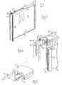
- a screen 1 is constructed from a rectangular honeycomb panel 2 mounted within top and bottom extrusions 3 and side extrusions 4.
- the screen 1 is provided with a fabric covering 5 on each side of the panel 2, and trim, such as end caps 6 (and possibly side trim, if required), may be clipped onto or over the side extrusions 4.
- the screen 1 may be used by itself or in connection with other screens to define e.g. a working area or office, within a larger space.
- the invention lies in the fastening of the fabric covering 5 onto the screen 1. This is achieved by clamping the fabric covering 5 in a channel 8 in each of the side extrusions 4 using a clamping bar 9.
- the side extrusions 4 are firstly mounted on the panel 2, and a fabric covering 5 is placed over one side of the panel 2. The edges of the covering 5 are then placed loosely within a channel 8 of each of the side extrusions 4, and are clamped in place by inserting a clamping bar 9 into each channel 8. This is repeated for the fabric covering for the other side of the panel 2.
- the clamping bar 9 may be of a material which deforms slightly, e.g. flexible PVC or a co-extruded plastic extrusion, so as to provide a firm clamping action on insertion into the channel 8, and may have serrations 10 along its sides to ensure a firm engagement with the channel 8 (which may also have serrations 11 along its sides).
- the serrations 10,11 also ensure that the fabric covering 5 is held firmly in place between the channel 8 and clamping bar 9.
- top and bottom extrusions 3 are mounted on the panel 2, and are connected to the side extrusions 4 by screws 12 (see Fig. 2) which engage with screw fixing portions 13 (see Fig. 3).
- the top and bottom extrusions 3 have flange portions 3a which extend over the top and bottom edges of the fabric covering 5 on each side of the panel 2 so as to provide a neat finish.
- the end caps 6 are clip-mounted to the extrusions 4 to complete the screen 1.
- the side extrusions 4 also have engagement portions 14 which allow the screen 1 to be attached to further such screens via a suitably shaped linking extrusion (not shown).
- the resulting screen 1 of Fig. 1 contrasts markedly with prior art screens in which the coverings are attached to the screens using staples and glue.
- the present screen assembly allows the coverings 5 to be replaced quickly and easily and without the need for a skilled upholsterer or for the removal of the screen.
- the ease with which the coverings 5 may be replaced provides the opportunity to change their colour or pattern more often and/or to have frequent changes of e.g. advertisements and the like printed on the coverings.
- the coverings themselves may be made of any suitable materials, and could be for example fabric, or similar material, or vinyl with printed graphics or the like.
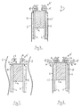
- Figs. 4-6 show a cross-section through the side extrusion 4' of a screen 1 made in accordance with a second embodiment at various stages of the screen's construction, with similar features being given the same reference numerals as in the first embodiment.
- the screen 1 is constructed from a pair of opposed e.g. rectangular panels 2 of e.g. hardboard, between which are mounted spacer elements 14 of e.g. ply, chipboard or MDF (one along each edge of the screen, or at least along two opposite edges of the screen).
- spacer elements 14 e.g. ply, chipboard or MDF (one along each edge of the screen, or at least along two opposite edges of the screen).
- the panels 2 are held together by the side extrusions 4' which may be e.g. of aluminium.
- Foam padding 15 is provided on the front face of each panel 2 for soundproofing, and the fabric coverings 5 are provided over the front of the panels 2 and padding 15 for decoration.
- a screen 1 in order to construct a screen 1, first the two panels 2 are placed opposite one another and the spacer elements 14 are fixed between them by staples, one along each side edge of the panels.
- the foam padding 15 is then glued onto the front of each panel 2.
- the padding 15 is cut shorter than the panels 2, so that it does not reach the edges of the panels. This leaves space for panel retaining flanges 16 of the extrusions 4', the extrusions 4' being mounted along the edges of the panels 2 by being screwed onto the spacer elements 14.
- each side extrusion 4' of the screen 1 (i.e. the vertical end posts of the screen) includes the clamping channels 8 for holding the coverings 5.
- top and bottom extrusions of the screen may also be of the same form as the side extrusions 4'. They do not however need the channels 8, and so may take a simpler form if desired, e.g. as in Fig. 3, and may be held in place by screw mounting directly to the ends of the side extrusions 4'.
- the fabric coverings 5 may be added. Firstly, the coverings 5 are cut to size. Next, as shown in Fig. 6, they are placed on the panels 2 with their edges 5a placed loosely within the channels 8. The edges 5a are then clamped in position by inserting a clamping extrusion 9' of e.g. PVC into each channel 8.
- a clamping extrusion 9' of e.g. PVC
- the clamping extrusions 9' may be of U-shaped cross-section, so that the legs 9a' are pressed towards one another on insertion of the extrusions 9' into the channels 8, to provide a firm clamping action.
- the extrusion 9' and channels 8 may also have the serrations 10,11 along their sides as in the first embodiment.
- Clamping of the coverings 5 may occur along any two opposed edges of the screen, or along all four edges. Thus, instead of the two side edges discussed above, clamping may alternatively or in addition take place along the top and bottom edges of the screen as well.
- Fig. 7 shows two screens 1 attached to one another by connector elements 17, which are strips of aluminium or plastic extrusion having a "dumbbell" cross-section.
- Each longitudinal end of the strip connector 17 is mounted in one of a number of correspondingly shaped connection channels 18 in the extrusions 4'.
- the provision of a number of differently angled connection channels 18 allows for different angles of connection between the screens, and e.g. the right-angled connection shown in Fig. 8.
- the arrangement of Fig. 7 may be found along a wall portion of a screened area, whilst the arrangement of Fig. 8 may be found at a corner.
- the extrusions 4' are multi-purpose. They mount the coverings 5, allow the screens 1 to connect to one another, and hold the panels 2 and spacer elements 14 together.
- trims may be provided over the extrusions 4', so as to provide a pleasing aesthetic effect.
- the trims may take any desired shape, and an example of a trim is shown in the following, third, embodiment of the present invention.
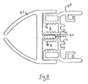
- the extrusions used to clamp the coverings 5 are top and bottom extrusions 3' of the screen 1, rather than side extrusions 4 or 4'.
- extrusions 3' have the clamping channels 8 mounted on their end face rather than at their sides, and use solid clamping bars 9'' to wedge the coverings 5 in position.
- the extrusions 3' also differ from those of the previous embodiment in that they include channels 19 for mounting the panels 2, so that the spacer elements 14 are not required.
- the space between the panels 2 may be filled e.g. by soundproofing material 20.
- Fig. 9 shows a top trim element 21 mounted on the top extrusion 3' to provide an aesthetically pleasing finish to the screen 1.
- the trim element 21 is fixed onto the extrusion 3' by a christmas tree connector 22 which pushes into a central fixing channel 23 on the extrusion 3'.
- the fabric coverings 5 cover the sides of the extrusion 3', and so the trim 21 may be of a shallower depth than would be used in the prior art, where the trim would need to extend over the whole of the extrusion 3'.
- Fig. 10 shows the extrusion 3' of Fig. 9 used as a bottom extrusion of the screen 1, and with a suitable bottom trim 24 mounted thereon.
- Fig. 11 shows a fourth embodiment of the invention in which the extrusion 3' of Fig. 9 is used as a side extrusion 4'' (so that clamping of the coverings 5 takes place between the side extrusions of the screen), and shows a possible side trim 25.
- the clamping extrusion or bar could take any other suitable form, and could comprise a number of clamping channels and/or bars spaced along the screen extrusion, rather than a continuous channel or bar.
- the clamping action could be provided by one or more protrusions along an extrusion, with one or more clamping elements clipping over the protrusion(s) to clamp an edge of the screen covering therebetween.
- a single clamping channel 8 might be used for the coverings 5 of both sides of the screen 1, or only one covering on one side might be necessary.
- the channels could also face any suitable direction other than from the side or from the top face, and for example could be at 45° to the side and face channels mentioned above.
- the edges 5a of the coverings 5 which are to be clamped may be attached to the clamping bars 9, e.g. by being threaded through a slot in the bars, before the bars are inserted into the clamping channels 8.
Landscapes
- Engineering & Computer Science (AREA)
- Architecture (AREA)
- Physics & Mathematics (AREA)
- Electromagnetism (AREA)
- Civil Engineering (AREA)
- Structural Engineering (AREA)
- Curtains And Furnishings For Windows Or Doors (AREA)
- Extrusion Moulding Of Plastics Or The Like (AREA)
Applications Claiming Priority (2)
| Application Number | Priority Date | Filing Date | Title |
|---|---|---|---|
| GB9901345A GB2345846A (en) | 1999-01-21 | 1999-01-21 | Screen assembly |
| GB9901345 | 1999-01-21 |
Publications (1)
| Publication Number | Publication Date |
|---|---|
| EP1022402A1 true EP1022402A1 (fr) | 2000-07-26 |
Family
ID=10846277
Family Applications (1)
| Application Number | Title | Priority Date | Filing Date |
|---|---|---|---|
| EP00300445A Withdrawn EP1022402A1 (fr) | 1999-01-21 | 2000-01-21 | Assemblage de panneaux |
Country Status (2)
| Country | Link |
|---|---|
| EP (1) | EP1022402A1 (fr) |
| GB (1) | GB2345846A (fr) |
Cited By (3)
| Publication number | Priority date | Publication date | Assignee | Title |
|---|---|---|---|---|
| EP1522644A1 (fr) * | 2003-10-06 | 2005-04-13 | Geurts, W.H.J.M. | Profilés constitués de plaques pour murs, sols et toits |
| DE102011053818A1 (de) * | 2011-09-21 | 2013-03-21 | Ehmki Schmid & Co. | Stellwand, damit ausbildbares Stellwandsystem sowie technisches Gewebe hierfür |
| JP2016522336A (ja) * | 2013-03-15 | 2016-07-28 | ハーマン、ミラー、インコーポレイテッドHerman Miller Incorporated | スクリーン組立体 |
Citations (5)
| Publication number | Priority date | Publication date | Assignee | Title |
|---|---|---|---|---|
| US4215765A (en) * | 1978-12-26 | 1980-08-05 | Owens-Corning Fiberglas Corporation | Acoustical wall baffle and method of making |
| FR2637631A1 (fr) * | 1988-10-06 | 1990-04-13 | Chenel Guy | Panneau de cloison de stand d'exposition |
| US5086606A (en) * | 1991-02-20 | 1992-02-11 | Krueger International, Inc. | Office panel partition and frame therefore |
| FR2668520A1 (fr) * | 1990-10-30 | 1992-04-30 | Tec Ab | Profilies metalliques pour cloisons modulaires. |
| EP0826842A1 (fr) * | 1996-08-27 | 1998-03-04 | Steelcase Strafor | Nouvelle cloison |
Family Cites Families (2)
| Publication number | Priority date | Publication date | Assignee | Title |
|---|---|---|---|---|
| US4601137A (en) * | 1983-07-29 | 1986-07-22 | The Tandem Group, Inc. | Locking mechanism for an office panel system |
| CN2085823U (zh) * | 1990-12-10 | 1991-10-02 | 薛仁雄 | 如意隔间骨材 |
-
1999
- 1999-01-21 GB GB9901345A patent/GB2345846A/en not_active Withdrawn
-
2000
- 2000-01-21 EP EP00300445A patent/EP1022402A1/fr not_active Withdrawn
Patent Citations (5)
| Publication number | Priority date | Publication date | Assignee | Title |
|---|---|---|---|---|
| US4215765A (en) * | 1978-12-26 | 1980-08-05 | Owens-Corning Fiberglas Corporation | Acoustical wall baffle and method of making |
| FR2637631A1 (fr) * | 1988-10-06 | 1990-04-13 | Chenel Guy | Panneau de cloison de stand d'exposition |
| FR2668520A1 (fr) * | 1990-10-30 | 1992-04-30 | Tec Ab | Profilies metalliques pour cloisons modulaires. |
| US5086606A (en) * | 1991-02-20 | 1992-02-11 | Krueger International, Inc. | Office panel partition and frame therefore |
| EP0826842A1 (fr) * | 1996-08-27 | 1998-03-04 | Steelcase Strafor | Nouvelle cloison |
Cited By (4)
| Publication number | Priority date | Publication date | Assignee | Title |
|---|---|---|---|---|
| EP1522644A1 (fr) * | 2003-10-06 | 2005-04-13 | Geurts, W.H.J.M. | Profilés constitués de plaques pour murs, sols et toits |
| DE102011053818A1 (de) * | 2011-09-21 | 2013-03-21 | Ehmki Schmid & Co. | Stellwand, damit ausbildbares Stellwandsystem sowie technisches Gewebe hierfür |
| JP2016522336A (ja) * | 2013-03-15 | 2016-07-28 | ハーマン、ミラー、インコーポレイテッドHerman Miller Incorporated | スクリーン組立体 |
| EP2971396A4 (fr) * | 2013-03-15 | 2016-12-07 | Miller Herman Inc | Ensemble écran |
Also Published As
| Publication number | Publication date |
|---|---|
| GB2345846A (en) | 2000-07-26 |
| GB9901345D0 (en) | 1999-03-10 |
Similar Documents
| Publication | Publication Date | Title |
|---|---|---|
| US8205395B2 (en) | Wall system and method of installation of a wall system | |
| US6167665B1 (en) | Corner post for a wall panel system | |
| US10550581B2 (en) | Cork-based tile for privacy apparatuses and method of making and using the same | |
| US3892189A (en) | Modular shelf construction | |
| US4821477A (en) | Partition panel system | |
| US7089708B1 (en) | Wall paneling assembly and system | |
| US5586593A (en) | Partitioning system | |
| CA2068506C (fr) | Panneau vitre pre-assemble avec garnitures pour systemes de panneaux muraux | |
| AU2015246104B2 (en) | Surface coverings including decorative strips | |
| US20030089057A1 (en) | Floor-to-ceiling wall panel system | |
| WO2007037702A1 (fr) | Raccord de lambrissage | |
| US20170354246A1 (en) | Functional rail and worksurface support | |
| US5520234A (en) | Window top decorating assembly | |
| US6170213B1 (en) | Wall panel mounting system and method | |
| CA2237749C (fr) | Boite de valence | |
| EP1022402A1 (fr) | Assemblage de panneaux | |
| US7971404B2 (en) | Systems and methods for installing panels | |
| EP0333519A1 (fr) | Tableaux d'affichage et leur montage | |
| US20030074858A1 (en) | Support rail | |
| US12281471B2 (en) | Panel with inset glass | |
| IES20000446A2 (en) | A desk system | |
| AU2005227395B2 (en) | Panel assembly and method of installation thereof | |
| AU628089B2 (en) | Modular panelling system | |
| GB2205870A (en) | Wall cladding | |
| GB2304039A (en) | Adjustable cover panel assembly |
Legal Events
| Date | Code | Title | Description |
|---|---|---|---|
| PUAI | Public reference made under article 153(3) epc to a published international application that has entered the european phase |
Free format text: ORIGINAL CODE: 0009012 |
|
| AK | Designated contracting states |
Kind code of ref document: A1 Designated state(s): AT BE CH CY DE DK ES FI FR GB GR IE IT LI LU MC NL PT SE |
|
| AX | Request for extension of the european patent |
Free format text: AL;LT;LV;MK;RO;SI |
|
| AKX | Designation fees paid | ||
| STAA | Information on the status of an ep patent application or granted ep patent |
Free format text: STATUS: THE APPLICATION IS DEEMED TO BE WITHDRAWN |
|
| 18D | Application deemed to be withdrawn |
Effective date: 20010127 |
|
| REG | Reference to a national code |
Ref country code: DE Ref legal event code: 8566 |