EP1022460A2 - Montageverfahren - Google Patents
Montageverfahren Download PDFInfo
- Publication number
- EP1022460A2 EP1022460A2 EP00100847A EP00100847A EP1022460A2 EP 1022460 A2 EP1022460 A2 EP 1022460A2 EP 00100847 A EP00100847 A EP 00100847A EP 00100847 A EP00100847 A EP 00100847A EP 1022460 A2 EP1022460 A2 EP 1022460A2
- Authority
- EP
- European Patent Office
- Prior art keywords
- pump
- suction
- pressure
- valve
- units
- Prior art date
- Legal status (The legal status is an assumption and is not a legal conclusion. Google has not performed a legal analysis and makes no representation as to the accuracy of the status listed.)
- Granted
Links
- 238000000034 method Methods 0.000 title claims abstract description 19
- 238000006073 displacement reaction Methods 0.000 claims abstract description 4
- 230000002706 hydrostatic effect Effects 0.000 claims description 6
- 238000005086 pumping Methods 0.000 claims description 6
- 238000009434 installation Methods 0.000 claims description 2
- 230000001174 ascending effect Effects 0.000 claims 1
- 230000006835 compression Effects 0.000 abstract description 2
- 238000007906 compression Methods 0.000 abstract description 2
- 230000006698 induction Effects 0.000 abstract 3
- 239000000446 fuel Substances 0.000 description 9
- 238000002347 injection Methods 0.000 description 7
- 239000007924 injection Substances 0.000 description 7
- 230000010349 pulsation Effects 0.000 description 7
- 238000010586 diagram Methods 0.000 description 3
- 230000001419 dependent effect Effects 0.000 description 2
- 238000004519 manufacturing process Methods 0.000 description 2
- 230000000712 assembly Effects 0.000 description 1
- 238000000429 assembly Methods 0.000 description 1
- 238000010276 construction Methods 0.000 description 1
- 238000011161 development Methods 0.000 description 1
- 230000018109 developmental process Effects 0.000 description 1
- 230000002028 premature Effects 0.000 description 1
- 238000011144 upstream manufacturing Methods 0.000 description 1
- 239000011800 void material Substances 0.000 description 1
- XLYOFNOQVPJJNP-UHFFFAOYSA-N water Substances O XLYOFNOQVPJJNP-UHFFFAOYSA-N 0.000 description 1
Images


Classifications
-
- F—MECHANICAL ENGINEERING; LIGHTING; HEATING; WEAPONS; BLASTING
- F04—POSITIVE - DISPLACEMENT MACHINES FOR LIQUIDS; PUMPS FOR LIQUIDS OR ELASTIC FLUIDS
- F04B—POSITIVE-DISPLACEMENT MACHINES FOR LIQUIDS; PUMPS
- F04B1/00—Multi-cylinder machines or pumps characterised by number or arrangement of cylinders
- F04B1/04—Multi-cylinder machines or pumps characterised by number or arrangement of cylinders having cylinders in star- or fan-arrangement
- F04B1/0404—Details or component parts
-
- F—MECHANICAL ENGINEERING; LIGHTING; HEATING; WEAPONS; BLASTING
- F02—COMBUSTION ENGINES; HOT-GAS OR COMBUSTION-PRODUCT ENGINE PLANTS
- F02M—SUPPLYING COMBUSTION ENGINES IN GENERAL WITH COMBUSTIBLE MIXTURES OR CONSTITUENTS THEREOF
- F02M59/00—Pumps specially adapted for fuel-injection and not provided for in groups F02M39/00 -F02M57/00, e.g. rotary cylinder-block type of pumps
- F02M59/44—Details, components parts, or accessories not provided for in, or of interest apart from, the apparatus of groups F02M59/02 - F02M59/42; Pumps having transducers, e.g. to measure displacement of pump rack or piston
- F02M59/48—Assembling; Disassembling; Replacing
-
- F—MECHANICAL ENGINEERING; LIGHTING; HEATING; WEAPONS; BLASTING
- F02—COMBUSTION ENGINES; HOT-GAS OR COMBUSTION-PRODUCT ENGINE PLANTS
- F02M—SUPPLYING COMBUSTION ENGINES IN GENERAL WITH COMBUSTIBLE MIXTURES OR CONSTITUENTS THEREOF
- F02M63/00—Other fuel-injection apparatus having pertinent characteristics not provided for in groups F02M39/00 - F02M57/00 or F02M67/00; Details, component parts, or accessories of fuel-injection apparatus, not provided for in, or of interest apart from, the apparatus of groups F02M39/00 - F02M61/00 or F02M67/00; Combination of fuel pump with other devices, e.g. lubricating oil pump
- F02M63/02—Fuel-injection apparatus having several injectors fed by a common pumping element, or having several pumping elements feeding a common injector; Fuel-injection apparatus having provisions for cutting-out pumps, pumping elements, or injectors; Fuel-injection apparatus having provisions for variably interconnecting pumping elements and injectors alternatively
- F02M63/0225—Fuel-injection apparatus having a common rail feeding several injectors ; Means for varying pressure in common rails; Pumps feeding common rails
-
- F—MECHANICAL ENGINEERING; LIGHTING; HEATING; WEAPONS; BLASTING
- F04—POSITIVE - DISPLACEMENT MACHINES FOR LIQUIDS; PUMPS FOR LIQUIDS OR ELASTIC FLUIDS
- F04B—POSITIVE-DISPLACEMENT MACHINES FOR LIQUIDS; PUMPS
- F04B23/00—Pumping installations or systems
- F04B23/04—Combinations of two or more pumps
- F04B23/06—Combinations of two or more pumps the pumps being all of reciprocating positive-displacement type
-
- F—MECHANICAL ENGINEERING; LIGHTING; HEATING; WEAPONS; BLASTING
- F04—POSITIVE - DISPLACEMENT MACHINES FOR LIQUIDS; PUMPS FOR LIQUIDS OR ELASTIC FLUIDS
- F04B—POSITIVE-DISPLACEMENT MACHINES FOR LIQUIDS; PUMPS
- F04B49/00—Control, e.g. of pump delivery, or pump pressure of, or safety measures for, machines, pumps, or pumping installations, not otherwise provided for, or of interest apart from, groups F04B1/00 - F04B47/00
- F04B49/22—Control, e.g. of pump delivery, or pump pressure of, or safety measures for, machines, pumps, or pumping installations, not otherwise provided for, or of interest apart from, groups F04B1/00 - F04B47/00 by means of valves
- F04B49/225—Control, e.g. of pump delivery, or pump pressure of, or safety measures for, machines, pumps, or pumping installations, not otherwise provided for, or of interest apart from, groups F04B1/00 - F04B47/00 by means of valves with throttling valves or valves varying the pump inlet opening or the outlet opening
-
- F—MECHANICAL ENGINEERING; LIGHTING; HEATING; WEAPONS; BLASTING
- F04—POSITIVE - DISPLACEMENT MACHINES FOR LIQUIDS; PUMPS FOR LIQUIDS OR ELASTIC FLUIDS
- F04B—POSITIVE-DISPLACEMENT MACHINES FOR LIQUIDS; PUMPS
- F04B51/00—Testing machines, pumps, or pumping installations
Definitions
- the invention relates to a method for assembling a hydrostatic pump with several in one pump housing recorded pump units according to the preamble of claim 1 and a radial piston pump assembled according to the method.
- the hydrostatic pumps assembled according to the procedure can be used as a radial piston pump to generate high pressures, for example, in the pressure range from 50 to 1000 bar become. Areas of application can be found in the Vehicle, industrial, flight and water hydraulics and in particular in mobile hydraulics and - increasingly recently - in common rail fuel injection systems.
- the Radial piston pumps are designed as variable pumps, whereby the volume setting etc. by stroke adjustment or can be done by suction throttling. Especially in applications where the device engineering effort is minimal should be and furthermore an optimal efficiency if partial funding is sought, the suction throttled Variable pumps of the constructions with stroke adjustment preferred.
- the suction valves are usually spring-loaded Check valves are formed in which a suction valve body via a suction valve spring against a valve seat is biased.
- the suction valve body can against the Force of the suction valve spring by the pressure difference between the pressure downstream of the intake throttle valve and in the cylinder chamber the assigned pump unit, i.e. by the pressure difference be opened above the suction valve body.
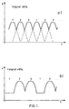
- FIG. 1 two diagrams are shown in which the pressure p is one Radial piston pump with three pump units over time t is shown.
- the diagram of Figure 1a shows the Pressure conditions with a low throttling of the volume flow to the pump, the degree of filling, for example 50% may be.
- Figure 1b shows the pressure conditions at a lower filling level of, for example, 10%. Because of the temporally successive pumping units there is no constant pressure at the outlet of the radial piston pump but a pressure pulsation, with each peak 1, 2, 3 the Compression stroke of the assigned 1st, 2nd or 3rd pump unit corresponds.
- the pump unit 1 conveys one Filling level of 10% no longer, so that there is a strong Pressure and volume flow pulsation at the pressure connection of the pump sets.
- the invention is based on the object a method of assembling a hydrostatic pump and a radial piston pump installed according to this procedure create where the pressure and volume flow pulsation is minimized at low filling levels.
- the pressure areas are dimensioned so narrow that the premature Switching off one or more pump units is practical is excluded.
- the print areas can, for example as equal pressure intervals with 1/10 bar steps or larger with increasing suction opening pressure are going to be determined. That is, the print areas can for example with a 0.7 bar suction valve spring in groups from 0.6 to 0.7 bar; 0.7 to 0.8 bar; 0.8 to 0.9 bar ... or with increasing intervals - such as 0.7 to 0.77 bar; 0.78 to 0.86 bar; 0.87 to 0.96 bar ... to get voted.
- the invention can be particularly advantageous in a Use a radial piston pump with three or more pump units, which, for example, as a high-pressure pump in a common rail fuel injection system is used and with the pressures up to 1500 bar can be generated.
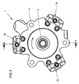
- FIGS 2 and 3 show views of a radial piston pump 1 with three pumping units 2a, 2b, 2c, which are operated by one common drive shaft 4 are driven.
- the Pump units 2a, 2b, 2c and the drive shaft 4 are in a pump housing 6 mounted on the also a suction port 8 and a pressure connection 10 (Figure 2) are formed.
- FIG. 2 shows a partial sectional view along the Line A-A in Figure 3.
- the drive shaft 4 has an eccentric 12, on which an eccentric ring 16 is guided via a slide ring 14 is.
- Each of the pump units by way of example based on FIG. 2 only the pump unit 2a is described has one Piston 18 of a slide shoe 20 on a flat of the eccentric ring 16 is supported.
- Each pump unit 2 has a displacement housing 22 in which the piston 18 is guided axially and with a in the radial direction expanded cylinder head 24 on a Mounting flange 26 of the pump housing 6 is attached.
- a suction valve 28 is received in the cylinder head 24, through which the suction port 8 with the cylinder chamber 30 of the Displacer housing 22 is connectable.
- the pressurized pressure medium (fuel) is led through an angular bore 32 to a pressure valve 34, that in the parting plane between the cylinder head 24 and the Mounting flange 26 is formed. Downstream of the Pressure valve 34 is a pressure channel 36 in the pump housing 6 formed in a connected to the pressure port 10 Collection channel 38 opens.
- the suction port is over a suction line 40 connected to a suction throttle valve 42, through which the from a tank T by means of a prefeed pump 44 fuel flow rate is throttled to adjust the filling level of the radial piston pump 1.
- the Suction throttle valve 42 can, for example, be proportional adjustable two-way valve that runs over the motor control is activated.
- the fuel delivered by the pump units 2a, 2b, 2c is conveyed to the common rail via the pressure connection 10, is arranged in the fuel injection nozzles 48.
- the other components of the common rail injection system are in the highly simplified representation according to Figure 2 not taken into account as this for understanding the invention are of minor importance.
- Control of the radial piston pump 1 (high pressure pump) and of the suction throttle valve 42 vary.
- the suction valve 28 can be a preassembled unit, for example in cartridge design etc. in the displacer housing 22 are screwed in or, as in the case in FIG 2 shown embodiment directly in the displacer 22 be mounted.
- FIG. 4 shows a detailed representation, of the suction valve 28 from FIG. 2.
- valve seat insert 52 is screwed in, on the one hand forms a valve seat 54 and on the other hand the Receiving hole 50 seals to the outside.
- a suction valve spring 56 supported, via which a suction valve body 58 against the Valve seat 54 is biased.
- the suction valve insert 52 has a valve seat side Blind hole 60, the radial holes 62 in one Annulus 64 opens out via a suction channel with the suction connection 8 is connected.
- the suction valve spring 56 is for example designed as a 0.7 bar spring, i.e. the pressure on the valve seat end face of the suction valve body 58 must be 0.7 bar higher than the pressure at the back of the Suction valve body 58 against the suction valve body 58 to lift the force of the suction valve spring 56 from the valve seat 54.
- this only applies if the manufacturing tolerances of the components according to the specifications and the suction valve spring are a first approximation has spring characteristic independent of the path. In the In practice, however, these requirements are only disproportionate big effort realizable, so that the opening pressure for the suction valve 28 from the predetermined opening pressure (0.7 bar) deviates and changes when operating the radial piston pump adjust the irregularities shown in Figure 1b.
- the pre-assembled pump units are now 2a, 2b, 2c, with the suction valve 28 and possibly the piston 18 subjected to a preliminary test in which the individual Suction valve opening pressure determined for each pump unit 2a becomes.
- these groups can include, for example, pressure intervals of 0.1 bar based on a minimum pressure of 0.6 bar or pressure intervals dependent on the pressure level.
- group 1 2nd 3rd 4th 5 constant pressure intervals (bar) 0.6 - 0.71 - 0.81 - 0.91 - 1.1 - 0.7 0.8 0.9 1.0 1.2
- Variable pressure interval (bar) 0.6 - 0.67 - 0.75 - 0.84 - 0.93 - 0.66 0.74 0.83 0.93 1.03
- the selection process according to the invention can be also with other suction-restricted pump types deploy.
- a method for assembling a suction-throttled device is disclosed hydrostatic pump with multiple pump units, at which the suction valve opening pressure of each pump unit checked before installation in the pump housing and only Pump units or suction valve units are installed, whose suction valve opening pressures are within a predetermined Pressure interval.
Landscapes
- Engineering & Computer Science (AREA)
- Mechanical Engineering (AREA)
- General Engineering & Computer Science (AREA)
- Chemical & Material Sciences (AREA)
- Combustion & Propulsion (AREA)
- Details Of Reciprocating Pumps (AREA)
- Fuel-Injection Apparatus (AREA)
- Reciprocating Pumps (AREA)
Abstract
Description
| Gruppe | 1 | 2 | 3 | 4 | 5 |
| konstante Druckintervalle (bar) | 0,6 - | 0,71 - | 0,81 - | 0,91 - | 1,1 - |
| 0,7 | 0,8 | 0,9 | 1,0 | 1,2 | |
| Variabler Druckintervall (bar) | 0,6 - | 0,67 - | 0,75 - | 0,84 - | 0,93 - |
| 0,66 | 0,74 | 0,83 | 0,93 | 1,03 |
Claims (9)
- Verfahren zur Montage einer sauggedrosselten hydrostatischen Pumpe (1) mit mehreren in einem Pumpengehäuse (6) aufgenommenen Pumpeinheiten (2a, 2b, 2c), deren Kolben (18) von einer Antriebswelle (4) angetrieben sind und die jeweils ein Saug- und ein Druckventil (28, 34) haben, über das Druckmittel aus einer Saugleitung (40) ansaugbar bzw. an einen Sammelkanal (38) abgebbar ist, gekennzeichnet durch die Schritte:Vormontage mehrerer Pumpeinheiten (2a, 2b, 2c) mit Verdrängergehäuse (22), Saugventil (28) und ggf. Kolben (18) und Druckventil (34);Prüfen mehrerer Pumpeinheiten (2a, 2b, 2c) vor der Montage ins Pumpengehäuse im Hinblick auf den jeweils erforderlichen Öffnungsdruck des Saugventils (28);Auswahl von Pumpeinheiten (2a, 2b, 2c,) deren Saugventilöffnungsdrück in einem vorbestimmten Druckintervall liegen undMontage der Pumpeinheiten (2a, 2b, 2c) einer Gruppe im Pumpengehäuse (6).
- Verfahren zur Montage einer hydrostatischen Pumpe (1) mit mehreren in einem Pumpengehäuse (6) aufgenommenenen Pumpeinheiten (2a, 2b, 2c), deren Kolben (18) von einer Antriebswelle (4) angetrieben sind, und die jeweils ein Saug- und ein Druckventil (28, 34) haben, über das Druckmittel aus einer Saugleitung (40) ansaugbar bzw. an einen Sammelkanal abgebbar ist, wobei zumindest das Saugventil (28) als Einbauventil ausgebildet ist, gekennzeichnet durch die Schritte:Vormontage mehrerer Saugventile (28);Prüfen mehrerer Saugventile (28) im Hinblick auf den erforderlichen Öffnungsdruck;Auswahl von Saugventilen (28), deren Öffnungsdruck in einem vorbestimmten Druckbereich liegt undMontage der Saugventile (28) in der Pumpeinheit (2a, 2b, 2c) oder im Pumpengehäuse (6).
- Verfahren nach Patentanspruch 1 oder 2, dadurch gekennzeichnet, daß die Druckbereiche aufsteigend jeweils gleiche Druckintervalle abdecken.
- Verfahren nach Patentanspruch 1 oder 2, dadurch gekennzeichnet, daß die Druckbereiche Druckintervalle abdecken, die mit zunehmenden Druck größer werden.
- Verfahren nach Patentanspruch 4, dadurch gekennzeichnet, daß die Druckintervalle proportional zu den Minimaldrücken der jeweiligen Druckintervalle ansteigen.
- Verfahren nach einem der vorhergehenden Patentansprüche, dadurch gekennzeichnet, daß die Pumpe eine sauggedrosselte Radialkolbenpumpe (1) ist, in deren Pumpengehäuse (6) eine Anzahl von zumindest drei Pumpeinheiten (2a, 2b, 2c) montiert wird, so daß eine Gruppe zumindest drei Pumpeinheiten (2a, 2b, 2c) enthalten muß.
- Verfahren nach Patentanspruch 6, dadurch gekennzeichnet, daß sich die Druckbereiche von einem unteren Grenzwert, insbesondere 0,6 bar, ausgehend über jeweils 0,1 bar erstrecken oder von dem unteren Grenzwert ausgehend, über jeweils 10 % der unteren oder oberen Druckintervallgrenze erstrecken.
- Radialkolbenpumpe mit mehreren in einem Pumpengehäuse (6) aufgenommenen Pumpeinheiten (2a, 2b, 2c) deren Kolben (18) von einer Antriebswelle (4) angetrieben sind und die jeweils ein Saug- und ein Druckventil (28, 34) haben, über das Druckmittel aus einer Saugleitung (40) ansaugbar bzw. an ein Sammelkanal (38) abgebbar ist, dadurch gekennzeichnet, daß die Saugventile (28) jeder Pumpeinheit (2a, 2b, 2c) innerhalb eines vorbestimmten Saugventilöffnungsdruckintervalls öffnen.
- Radialkolbenpumpe nach Patentanspruche 8, dadurch gekennzeichnet, daß in einem Verdrängergehäuse (22) jeder Pumpeinheit (2a, 2b, 2c) eine Saugventilfeder (56) mit Saugventilkörper (58) und ein Ventilsitzeinsatz (52) abgestützt werden.
Applications Claiming Priority (2)
| Application Number | Priority Date | Filing Date | Title |
|---|---|---|---|
| DE19902259 | 1999-01-21 | ||
| DE19902259A DE19902259B4 (de) | 1999-01-21 | 1999-01-21 | Montageverfahren |
Publications (3)
| Publication Number | Publication Date |
|---|---|
| EP1022460A2 true EP1022460A2 (de) | 2000-07-26 |
| EP1022460A3 EP1022460A3 (de) | 2000-12-27 |
| EP1022460B1 EP1022460B1 (de) | 2004-03-24 |
Family
ID=7894934
Family Applications (1)
| Application Number | Title | Priority Date | Filing Date |
|---|---|---|---|
| EP00100847A Expired - Lifetime EP1022460B1 (de) | 1999-01-21 | 2000-01-17 | Montageverfahren |
Country Status (2)
| Country | Link |
|---|---|
| EP (1) | EP1022460B1 (de) |
| DE (2) | DE19902259B4 (de) |
Cited By (1)
| Publication number | Priority date | Publication date | Assignee | Title |
|---|---|---|---|---|
| EP1357283A3 (de) * | 2002-04-23 | 2004-09-22 | Robert Bosch Gmbh | Kraftstoffeinspritzeinrichtung für eine Brennkraftmaschine |
Families Citing this family (5)
| Publication number | Priority date | Publication date | Assignee | Title |
|---|---|---|---|---|
| DE102007002729B3 (de) * | 2007-01-18 | 2008-06-05 | Siemens Ag | Kraftstoffpumpe für Einspritzsysteme von Brennkraftmaschinen sowie Herstellungsverfahren hierfür |
| DE102007004605B4 (de) * | 2007-01-30 | 2009-08-13 | Continental Automotive Gmbh | Hochdruckpumpe und Einspritzanlage für eine Brennkraftmaschine mit einer Hochdruckpumpe |
| DE102007030749A1 (de) | 2007-07-02 | 2009-01-08 | Robert Bosch Gmbh | Ventilgesteuerte Hydropumpe |
| DE102007060262A1 (de) | 2007-12-14 | 2009-06-18 | Robert Bosch Gmbh | Pumpenanordnung und Verfahren zu deren Ansteuerung |
| DE102008048450B4 (de) * | 2008-09-23 | 2014-10-30 | Continental Automotive Gmbh | Saugventil für einen Zylinder der Kraftstoff-Hochdruckpumpe eines Common-Rail-Einspritzsystems |
Family Cites Families (5)
| Publication number | Priority date | Publication date | Assignee | Title |
|---|---|---|---|---|
| DE3800905A1 (de) * | 1988-01-14 | 1989-07-27 | Rexroth Mannesmann Gmbh | Pumpe, insbesondere axialkolbenpumpe |
| DE4027794C2 (de) * | 1990-09-01 | 2002-06-20 | Continental Teves Ag & Co Ohg | Hydraulische Radialkolbenpumpe |
| DE4228357A1 (de) * | 1992-08-26 | 1994-03-03 | Zahnradfabrik Friedrichshafen | Radialkolbenpumpe |
| US5701873A (en) * | 1993-11-08 | 1997-12-30 | Eidgenoessische Technische Hochschule Laboratorium Fuer Verbrennungsmotoren Und Verbrennungstechnik | Control device for a filling-ratio adjusting pump |
| WO1995025887A1 (de) * | 1994-03-23 | 1995-09-28 | Siemens Aktiengesellschaft | Anordnung zur einspritzung von kraftstoff in die zylinder einer brennkraftmaschine |
-
1999
- 1999-01-21 DE DE19902259A patent/DE19902259B4/de not_active Expired - Fee Related
-
2000
- 2000-01-17 EP EP00100847A patent/EP1022460B1/de not_active Expired - Lifetime
- 2000-01-17 DE DE50005753T patent/DE50005753D1/de not_active Expired - Lifetime
Non-Patent Citations (1)
| Title |
|---|
| None |
Cited By (2)
| Publication number | Priority date | Publication date | Assignee | Title |
|---|---|---|---|---|
| EP1357283A3 (de) * | 2002-04-23 | 2004-09-22 | Robert Bosch Gmbh | Kraftstoffeinspritzeinrichtung für eine Brennkraftmaschine |
| US6959694B2 (en) | 2002-04-23 | 2005-11-01 | Robert Bosch Gmbh | Fuel injection system for an internal combustion engine |
Also Published As
| Publication number | Publication date |
|---|---|
| DE19902259A1 (de) | 2000-07-27 |
| EP1022460A3 (de) | 2000-12-27 |
| EP1022460B1 (de) | 2004-03-24 |
| DE19902259B4 (de) | 2006-02-23 |
| DE50005753D1 (de) | 2004-04-29 |
Similar Documents
| Publication | Publication Date | Title |
|---|---|---|
| DE60122947T2 (de) | Vorrichtung zur Regelung des Durchflusses einer Hochdruckpumpe in einem Common-rail Kraftstoffeinspritzsystem einer Brennkraftmaschine | |
| DE102004013307B4 (de) | Kraftstoffhochdruckpumpe mit einem Druckbegrenzungsventil | |
| EP1411238B1 (de) | Druckbegrenzungsventil für ein Kraftstoffeinspritzsystem | |
| EP1671031B1 (de) | Fluidpumpe, insbesondere kraftstoffhochdruckpumpe, mit druckdämpfer | |
| DE102008059117B4 (de) | Hochdruckpumpenanordnung | |
| EP1119704A1 (de) | Pumpenanordnung zur kraftstoffhochdruckerzeugung | |
| DE102011089797A1 (de) | Überströmventil für ein Kraftstoffeinspritzsystem sowie Kraftstoffeinspritzsystem | |
| EP2406488A1 (de) | Saugventil für eine kraftstoffhochdruckpumpe | |
| DE19756087A1 (de) | Hochdruckpumpe zur Kraftstoffversorgung bei Kraftstoffeinspritzsystemen von Brennkraftmaschinen | |
| EP3058223B1 (de) | Ein hochdruckmedium führendes bauelement | |
| DE102013224387B4 (de) | Kraftstoffeinspritzsystem sowie Verfahren zum Betreiben eines Kraftstoffeinspritzsystems | |
| EP3714162A1 (de) | Verfahren zum betreiben eines kolbenverdichters und kolbenverdichter | |
| EP1022460B1 (de) | Montageverfahren | |
| DE10139055A1 (de) | Verfahren, Computerprogramm, Steuer- und/oder Regelgerät sowie Kraftstoffsystem für eine Brennkraftmaschine | |
| DE19920997B4 (de) | Radialkolbenpumpe | |
| DE19653339A1 (de) | Pumpenanordnung zur Förderung von Kraftstoff | |
| DE102009028609A1 (de) | Manuell betätigbare Pumpenvorrichtung | |
| DE10243148A1 (de) | Radialkolbenpumpeneinheit | |
| WO2004027250A1 (de) | Kraftstoffeinspritzanlage für brennkraftmaschinen | |
| DE112006000387B4 (de) | Gemeinsames Druckleitungssystem mit Druckverstärkung | |
| DE102007002729B3 (de) | Kraftstoffpumpe für Einspritzsysteme von Brennkraftmaschinen sowie Herstellungsverfahren hierfür | |
| DE102008041393A1 (de) | Kraftstoffsystem für eine Brennkraftmaschine | |
| DE102009028116A1 (de) | Kraftstoffhochdruckpumpe mit einem Druckbegrenzungsventil | |
| DE102007030224A1 (de) | Kraftstoffpumpe, insbesondere für ein Kraftstoffsystem einer Brennkraftmaschine | |
| DE19920998B4 (de) | Radialkolbenpumpe |
Legal Events
| Date | Code | Title | Description |
|---|---|---|---|
| PUAI | Public reference made under article 153(3) epc to a published international application that has entered the european phase |
Free format text: ORIGINAL CODE: 0009012 |
|
| AK | Designated contracting states |
Kind code of ref document: A2 Designated state(s): DE FR GB IT |
|
| AX | Request for extension of the european patent |
Free format text: AL;LT;LV;MK;RO;SI |
|
| PUAL | Search report despatched |
Free format text: ORIGINAL CODE: 0009013 |
|
| AK | Designated contracting states |
Kind code of ref document: A3 Designated state(s): AT BE CH CY DE DK ES FI FR GB GR IE IT LI LU MC NL PT SE |
|
| AX | Request for extension of the european patent |
Free format text: AL;LT;LV;MK;RO;SI |
|
| 17P | Request for examination filed |
Effective date: 20010122 |
|
| AKX | Designation fees paid |
Free format text: DE FR GB IT |
|
| GRAP | Despatch of communication of intention to grant a patent |
Free format text: ORIGINAL CODE: EPIDOSNIGR1 |
|
| GRAS | Grant fee paid |
Free format text: ORIGINAL CODE: EPIDOSNIGR3 |
|
| GRAA | (expected) grant |
Free format text: ORIGINAL CODE: 0009210 |
|
| AK | Designated contracting states |
Kind code of ref document: B1 Designated state(s): DE FR GB IT |
|
| REG | Reference to a national code |
Ref country code: GB Ref legal event code: FG4D Free format text: NOT ENGLISH |
|
| GBT | Gb: translation of ep patent filed (gb section 77(6)(a)/1977) |
Effective date: 20040324 |
|
| REF | Corresponds to: |
Ref document number: 50005753 Country of ref document: DE Date of ref document: 20040429 Kind code of ref document: P |
|
| ET | Fr: translation filed | ||
| PLBE | No opposition filed within time limit |
Free format text: ORIGINAL CODE: 0009261 |
|
| STAA | Information on the status of an ep patent application or granted ep patent |
Free format text: STATUS: NO OPPOSITION FILED WITHIN TIME LIMIT |
|
| 26N | No opposition filed |
Effective date: 20041228 |
|
| REG | Reference to a national code |
Ref country code: FR Ref legal event code: TP |
|
| REG | Reference to a national code |
Ref country code: GB Ref legal event code: 732E Free format text: REGISTERED BETWEEN 20110825 AND 20110831 |
|
| REG | Reference to a national code |
Ref country code: FR Ref legal event code: PLFP Year of fee payment: 17 |
|
| REG | Reference to a national code |
Ref country code: FR Ref legal event code: PLFP Year of fee payment: 18 |
|
| REG | Reference to a national code |
Ref country code: FR Ref legal event code: PLFP Year of fee payment: 19 |
|
| PGFP | Annual fee paid to national office [announced via postgrant information from national office to epo] |
Ref country code: DE Payment date: 20180131 Year of fee payment: 19 |
|
| PGFP | Annual fee paid to national office [announced via postgrant information from national office to epo] |
Ref country code: GB Payment date: 20190121 Year of fee payment: 20 Ref country code: IT Payment date: 20190124 Year of fee payment: 20 Ref country code: FR Payment date: 20190123 Year of fee payment: 20 |
|
| REG | Reference to a national code |
Ref country code: DE Ref legal event code: R119 Ref document number: 50005753 Country of ref document: DE |
|
| PG25 | Lapsed in a contracting state [announced via postgrant information from national office to epo] |
Ref country code: DE Free format text: LAPSE BECAUSE OF NON-PAYMENT OF DUE FEES Effective date: 20190801 |
|
| REG | Reference to a national code |
Ref country code: GB Ref legal event code: PE20 Expiry date: 20200116 |
|
| PG25 | Lapsed in a contracting state [announced via postgrant information from national office to epo] |
Ref country code: GB Free format text: LAPSE BECAUSE OF EXPIRATION OF PROTECTION Effective date: 20200116 |