EP1022754A2 - Schaltermodul - Google Patents
Schaltermodul Download PDFInfo
- Publication number
- EP1022754A2 EP1022754A2 EP00100614A EP00100614A EP1022754A2 EP 1022754 A2 EP1022754 A2 EP 1022754A2 EP 00100614 A EP00100614 A EP 00100614A EP 00100614 A EP00100614 A EP 00100614A EP 1022754 A2 EP1022754 A2 EP 1022754A2
- Authority
- EP
- European Patent Office
- Prior art keywords
- switch module
- display
- switches
- buttons
- switch
- Prior art date
- Legal status (The legal status is an assumption and is not a legal conclusion. Google has not performed a legal analysis and makes no representation as to the accuracy of the status listed.)
- Withdrawn
Links
Images
Classifications
-
- H—ELECTRICITY
- H01—ELECTRIC ELEMENTS
- H01H—ELECTRIC SWITCHES; RELAYS; SELECTORS; EMERGENCY PROTECTIVE DEVICES
- H01H9/00—Details of switching devices, not covered by groups H01H1/00 - H01H7/00
- H01H9/18—Distinguishing marks on switches, e.g. for indicating switch location in the dark; Adaptation of switches to receive distinguishing marks
- H01H9/181—Distinguishing marks on switches, e.g. for indicating switch location in the dark; Adaptation of switches to receive distinguishing marks using a programmable display, e.g. LED or LCD
-
- B—PERFORMING OPERATIONS; TRANSPORTING
- B60—VEHICLES IN GENERAL
- B60K—ARRANGEMENT OR MOUNTING OF PROPULSION UNITS OR OF TRANSMISSIONS IN VEHICLES; ARRANGEMENT OR MOUNTING OF PLURAL DIVERSE PRIME-MOVERS IN VEHICLES; AUXILIARY DRIVES FOR VEHICLES; INSTRUMENTATION OR DASHBOARDS FOR VEHICLES; ARRANGEMENTS IN CONNECTION WITH COOLING, AIR INTAKE, GAS EXHAUST OR FUEL SUPPLY OF PROPULSION UNITS IN VEHICLES
- B60K35/00—Instruments specially adapted for vehicles; Arrangement of instruments in or on vehicles
- B60K35/10—Input arrangements, i.e. from user to vehicle, associated with vehicle functions or specially adapted therefor
-
- B—PERFORMING OPERATIONS; TRANSPORTING
- B60—VEHICLES IN GENERAL
- B60K—ARRANGEMENT OR MOUNTING OF PROPULSION UNITS OR OF TRANSMISSIONS IN VEHICLES; ARRANGEMENT OR MOUNTING OF PLURAL DIVERSE PRIME-MOVERS IN VEHICLES; AUXILIARY DRIVES FOR VEHICLES; INSTRUMENTATION OR DASHBOARDS FOR VEHICLES; ARRANGEMENTS IN CONNECTION WITH COOLING, AIR INTAKE, GAS EXHAUST OR FUEL SUPPLY OF PROPULSION UNITS IN VEHICLES
- B60K2360/00—Indexing scheme associated with groups B60K35/00 or B60K37/00 relating to details of instruments or dashboards
- B60K2360/122—Instrument input devices with reconfigurable control functions, e.g. reconfigurable menus
-
- H—ELECTRICITY
- H01—ELECTRIC ELEMENTS
- H01H—ELECTRIC SWITCHES; RELAYS; SELECTORS; EMERGENCY PROTECTIVE DEVICES
- H01H2300/00—Orthogonal indexing scheme relating to electric switches, relays, selectors or emergency protective devices covered by H01H
- H01H2300/04—Programmable interface between a set of switches and a set of functions, e.g. for reconfiguration of a control panel
Definitions
- the invention relates to a switch module according to the preamble of the first Claim. It is based on a device for operating Facilities in a vehicle, as the applicant in the previous unpublished application DE 198 40 142.6. At that one described device, the switches or buttons are labeled by labeling the housing with a laser or by Insert correspondingly labeled insert plates into the front of the Housing. Such labeling of the switches or buttons is production-technically complex and produces a large number of variants, because Devices marked in this way are made to customer specifications have to. This goes for expensive warehousing and customer requirements considering disposition.
- the object of the present invention is from a Generic switch module to create a basic type in which the customer-specific labeling of its switches or buttons without mechanical or printing processing steps.
- the object is achieved by the features of the first claim.
- the dependent claims relate to advantageous refinements of the found Solution.
- the solution found is characterized in that in association with the Switches or buttons are provided with a display on which they can be freely programmed a symbolism can be displayed, which allows the assignment of each Switch or button to a specific consumer can be recognized.
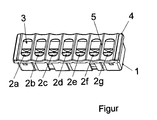
- FIG. 1 shows in a perspective view that a plurality of switches or buttons 2a to 2g are arranged in a housing 1 forming the switch module.
- a display 3 is provided, on which a symbolism can be displayed in a freely programmable manner, which symbolizes the association of each switch or button 2a to 2g with a particular consumer.
- a one-piece display 3 leading over the entire row of switches or keys, which is divided into as many fields by means of webs 5 formed in the housing cover 4 as there are switches or buttons 2a to 2g, whereby A pictogram or other suitable symbolism can be shown in each display field.
- the switch module is designed appropriately, several individual displays will be used. The decision in favor of one or the other display variant will have to be made according to the constructional circumstances from an economic point of view.
- the first variant is shown with the one-piece display.
- the display 3 is controlled by an electronic control circuit which is arranged either in the switch module or in a circuit arrangement connected to the switch module.
- the control of the display is freely programmable, so that any pictograms or symbol representations can be displayed.
- Chip-on-glass techniques can also be used for display control, in which the display desired on the display is generated directly on the display and not in a circuit arrangement that is spatially separate from the switch module.
- the use of a freely programmable display enables flexible use of the switch module. Changes in the switch or button assignment are easy to program and do not cause any design or printing changes on the switch module.
Landscapes
- Engineering & Computer Science (AREA)
- Chemical & Material Sciences (AREA)
- Combustion & Propulsion (AREA)
- Transportation (AREA)
- Mechanical Engineering (AREA)
- Push-Button Switches (AREA)
- Input From Keyboards Or The Like (AREA)
Abstract
Description
Claims (5)
- Schaltermodul, bestehend aus mehreren Schaltern oder Tastern (2a bis 2g), die in einem einzigen Gehäuse (1) angeordnet sind, wobei die Schalter oder Taster (2a bis 2g) der Betätigung von in einem Fahrzeug angeordneten elektrischen Verbrauchern oder Steuergeräten dienen,
dadurch gekennzeichnet, daß in Zuordnung zu den Schaltern oder Tastern (2a bis 2g) ein Display (3) vorgesehen ist, auf dem frei programmierbar eine Symbolik zur Anzeige gebracht werden kann, die die Zuordnung jedes Schalters oder Tasters (2a bis 2g) zu einem bestimmten Verbraucher erkennen läßt. - Schaltermodul nach Anspruch 1, dadurch gekennzeichnet, daß im Gehäuse (1) ein über die gesamte Schalter- bzw. Tastenreihe führendes Display (3) vorgesehen ist, das durch im Gehäusedeckel (4) angeformte Stege (5) in so viele Felder unterteilt ist, wie Schalter bzw. Taster (2a bis 2g) vorgesehen sind.
- Schaltermodul nach Anspruch 1, dadurch gekennzeichnet, daß mehrere einzelne Displays (3) vorgesehen sind, auf denen frei programmierbar eine Symbolik zur Anzeige gebracht werden kann, die die Zuordnung jedes Schalters oder Tasters (2a bis 2g) zu einem bestimmten Verbraucher erkennen lassen.
- Schaltermodul nach einem der vorangegangenen Ansprüche, dadurch gekennzeichnet, daß die Ansteuerung des oder der Displays (3) durch eine elektronische Steuerschaltung erfolgt, die entweder im Schaltermodul oder in einer mit dem Schaltermodul verbundenen Schaltungsanordnung angeordnet ist.
- Schaltermodul nach einem der vorangegangenen Ansprüche, dadurch gekennzeichnet, daß die Ansteuerung des oder der Displays (3) durch Einsatz der Chip-on-glas-Technik erfolgt, bei der die Erzeugung der auf dem Display (3) darzustellenden Symbolik unmittelbar am Display vorgenommen wird.
Applications Claiming Priority (2)
| Application Number | Priority Date | Filing Date | Title |
|---|---|---|---|
| DE19902604A DE19902604A1 (de) | 1999-01-23 | 1999-01-23 | Schaltermodul |
| DE19902604 | 1999-01-23 |
Publications (2)
| Publication Number | Publication Date |
|---|---|
| EP1022754A2 true EP1022754A2 (de) | 2000-07-26 |
| EP1022754A3 EP1022754A3 (de) | 2001-09-05 |
Family
ID=7895167
Family Applications (1)
| Application Number | Title | Priority Date | Filing Date |
|---|---|---|---|
| EP00100614A Withdrawn EP1022754A3 (de) | 1999-01-23 | 2000-01-13 | Schaltermodul |
Country Status (2)
| Country | Link |
|---|---|
| EP (1) | EP1022754A3 (de) |
| DE (1) | DE19902604A1 (de) |
Cited By (1)
| Publication number | Priority date | Publication date | Assignee | Title |
|---|---|---|---|---|
| EP1303424A4 (de) * | 2000-07-27 | 2004-12-01 | Int Truck Intellectual Prop Co | Programmierbarer matrix-regler zur korrelierung elektrischer geräte in motorfahrengen mit den schaltern eines schaltmoduls |
Families Citing this family (3)
| Publication number | Priority date | Publication date | Assignee | Title |
|---|---|---|---|---|
| DE10060981B4 (de) * | 2000-12-08 | 2004-02-26 | Hella Kg Hueck & Co. | Betätigungseinrichtung zum Auslösen wenigstens einer Funktion eines Kraftfahrzeugs |
| DE102005060605A1 (de) * | 2005-12-17 | 2007-06-21 | Bayerische Motoren Werke Ag | Bedieneinrichtung für ein Fahrzeug und Set von Bedieneinrichtungen |
| DE102006016092A1 (de) * | 2006-04-04 | 2007-10-25 | Johnson Controls Interiors Gmbh & Co. Kg | Bedieneinrichtung für ein Kraftfahrzeug mit haptisch unterscheidbarer Bedienoberfläche |
Family Cites Families (4)
| Publication number | Priority date | Publication date | Assignee | Title |
|---|---|---|---|---|
| JPS6144034A (ja) * | 1984-08-07 | 1986-03-03 | Omron Tateisi Electronics Co | 車両のスイツチ制御装置 |
| IT1182613B (it) * | 1985-10-15 | 1987-10-05 | Olivetti & Co Spa | Tasto con visualizzatore attivabile selettivamente e tastiera utilizzante tale tasto |
| DE3806042C2 (de) * | 1988-02-26 | 1994-09-15 | Ernst Gaertner | Optoelektronische Tastatur |
| JPH0863437A (ja) * | 1994-08-23 | 1996-03-08 | Mitsubishi Electric Corp | 携帯型情報端末機 |
-
1999
- 1999-01-23 DE DE19902604A patent/DE19902604A1/de not_active Ceased
-
2000
- 2000-01-13 EP EP00100614A patent/EP1022754A3/de not_active Withdrawn
Cited By (1)
| Publication number | Priority date | Publication date | Assignee | Title |
|---|---|---|---|---|
| EP1303424A4 (de) * | 2000-07-27 | 2004-12-01 | Int Truck Intellectual Prop Co | Programmierbarer matrix-regler zur korrelierung elektrischer geräte in motorfahrengen mit den schaltern eines schaltmoduls |
Also Published As
| Publication number | Publication date |
|---|---|
| EP1022754A3 (de) | 2001-09-05 |
| DE19902604A1 (de) | 2000-07-27 |
Similar Documents
| Publication | Publication Date | Title |
|---|---|---|
| DE102005043310B4 (de) | Anzeigesystem insbesondere für eine industrielle Automatisierungseinrichtung | |
| DE4306098A1 (de) | Einrichtung zum Steuern einzelner Funktionseinheiten einer Druckmaschine | |
| DE102008051401B4 (de) | Trainings- und Simulationsgerät für elektrische Funktionsabläufe in elektrischen, elektromechanischen und elektrofluidischen Anlagen | |
| EP0993995B1 (de) | Multifunktions-Bedienelement für den Einsatz in Kraftfahrzeugen | |
| DE3607945A1 (de) | Bedienungspult fuer drucker, insbesondere fuer matrixdrucker | |
| EP0844325B1 (de) | Betätigungs-und Anzeigevorrichtung | |
| EP0987138B1 (de) | Vorrichtung und Verfahren zum Anzeigen von Piktogrammen in einem Fahrzeug | |
| DE19910240A1 (de) | Bedienvorrichtung | |
| DE4022650C1 (de) | ||
| DE4306467B4 (de) | Steuerungseinrichtung, insbesondere für eine Werkzeugmaschine | |
| EP1022754A2 (de) | Schaltermodul | |
| EP0525612B1 (de) | Steuerfeld einer industriellen Anlage mit einer speicherprogrammierbaren Steuerung | |
| EP0079430B1 (de) | Anzeigevorrichtung | |
| DE10258563B9 (de) | Bedienblendeneinrichtung für ein elektrisches Haushaltsgroßgerät | |
| DE102016110904A1 (de) | Ventilbaugruppe | |
| EP0446396B1 (de) | Einrichtung zur Befehlsgabe für programmierbare Gebäudesystemtechnik | |
| DE102021209398A1 (de) | Fahrzeug, insbesondere Kraftfahrzeug, mit mindestens einer Vorrichtung zum Schutz beziehungsweise zur Darstellung eines Zeichens | |
| DE4424886C1 (de) | Verfahren zur Darstellung der Anlagenkonfiguration von beliebig auf mehreren Sammelschienen parallelgeschalteten Stufentransformatoren mit Spannungsregler und Monitorfeld zur Darstellung | |
| DE6908662U (de) | Registerbetaetigungseinrichtung in orgeln | |
| DE19851337B4 (de) | Anordnung zur Darstellung einer Oberfläche | |
| DE3134873C2 (de) | ||
| EP1511648A1 (de) | Segmentdisplay-anzeigevorrichtung | |
| EP0872993A2 (de) | Bedienerführung in Kommunikations-Endgeräten | |
| WO2006111487A2 (de) | Feldgerät mit einer bedieneinheit | |
| DE29617827U1 (de) | Steuerungseinrichtung für Solarien |
Legal Events
| Date | Code | Title | Description |
|---|---|---|---|
| PUAI | Public reference made under article 153(3) epc to a published international application that has entered the european phase |
Free format text: ORIGINAL CODE: 0009012 |
|
| AK | Designated contracting states |
Kind code of ref document: A2 Designated state(s): AT DE FR GB NL |
|
| AX | Request for extension of the european patent |
Free format text: AL;LT;LV;MK;RO;SI |
|
| PUAL | Search report despatched |
Free format text: ORIGINAL CODE: 0009013 |
|
| AK | Designated contracting states |
Kind code of ref document: A3 Designated state(s): AT DE FR GB NL |
|
| AX | Request for extension of the european patent |
Free format text: AL;LT;LV;MK;RO;SI |
|
| AKX | Designation fees paid | ||
| REG | Reference to a national code |
Ref country code: DE Ref legal event code: 8566 |
|
| STAA | Information on the status of an ep patent application or granted ep patent |
Free format text: STATUS: THE APPLICATION IS DEEMED TO BE WITHDRAWN |
|
| 18D | Application deemed to be withdrawn |
Effective date: 20020306 |