EP1022796A2 - Verfahren zum Betrieb eines Brennstoffzellensystems und Brennstoffzellensystem - Google Patents
Verfahren zum Betrieb eines Brennstoffzellensystems und Brennstoffzellensystem Download PDFInfo
- Publication number
- EP1022796A2 EP1022796A2 EP99122279A EP99122279A EP1022796A2 EP 1022796 A2 EP1022796 A2 EP 1022796A2 EP 99122279 A EP99122279 A EP 99122279A EP 99122279 A EP99122279 A EP 99122279A EP 1022796 A2 EP1022796 A2 EP 1022796A2
- Authority
- EP
- European Patent Office
- Prior art keywords
- fuel cell
- adsorption
- cell system
- desorption
- water
- Prior art date
- Legal status (The legal status is an assumption and is not a legal conclusion. Google has not performed a legal analysis and makes no representation as to the accuracy of the status listed.)
- Granted
Links
- 239000000446 fuel Substances 0.000 title claims abstract description 94
- 238000000034 method Methods 0.000 title claims description 15
- 238000001179 sorption measurement Methods 0.000 claims abstract description 28
- 238000003795 desorption Methods 0.000 claims abstract description 22
- 239000007788 liquid Substances 0.000 claims abstract description 19
- XLYOFNOQVPJJNP-UHFFFAOYSA-N water Substances O XLYOFNOQVPJJNP-UHFFFAOYSA-N 0.000 claims description 47
- 239000003463 adsorbent Substances 0.000 claims description 13
- 238000001816 cooling Methods 0.000 claims description 9
- 238000011084 recovery Methods 0.000 claims description 8
- 239000000126 substance Substances 0.000 claims description 5
- 239000012876 carrier material Substances 0.000 claims description 3
- 239000000498 cooling water Substances 0.000 claims description 3
- 238000004064 recycling Methods 0.000 claims 1
- GBMDVOWEEQVZKZ-UHFFFAOYSA-N methanol;hydrate Chemical compound O.OC GBMDVOWEEQVZKZ-UHFFFAOYSA-N 0.000 abstract description 5
- 239000000203 mixture Substances 0.000 abstract description 4
- 239000013589 supplement Substances 0.000 abstract description 2
- 239000007789 gas Substances 0.000 description 10
- 239000001257 hydrogen Substances 0.000 description 9
- 229910052739 hydrogen Inorganic materials 0.000 description 9
- UFHFLCQGNIYNRP-UHFFFAOYSA-N Hydrogen Chemical compound [H][H] UFHFLCQGNIYNRP-UHFFFAOYSA-N 0.000 description 8
- OKKJLVBELUTLKV-UHFFFAOYSA-N Methanol Chemical compound OC OKKJLVBELUTLKV-UHFFFAOYSA-N 0.000 description 6
- 229920005597 polymer membrane Polymers 0.000 description 5
- 239000000872 buffer Substances 0.000 description 4
- 239000007787 solid Substances 0.000 description 3
- 239000002250 absorbent Substances 0.000 description 2
- 230000002745 absorbent Effects 0.000 description 2
- QVGXLLKOCUKJST-UHFFFAOYSA-N atomic oxygen Chemical compound [O] QVGXLLKOCUKJST-UHFFFAOYSA-N 0.000 description 2
- 238000009833 condensation Methods 0.000 description 2
- 230000005494 condensation Effects 0.000 description 2
- 238000005516 engineering process Methods 0.000 description 2
- 239000012528 membrane Substances 0.000 description 2
- 239000003595 mist Substances 0.000 description 2
- 239000001301 oxygen Substances 0.000 description 2
- 229910052760 oxygen Inorganic materials 0.000 description 2
- 238000002407 reforming Methods 0.000 description 2
- 238000011144 upstream manufacturing Methods 0.000 description 2
- MYMOFIZGZYHOMD-UHFFFAOYSA-N Dioxygen Chemical compound O=O MYMOFIZGZYHOMD-UHFFFAOYSA-N 0.000 description 1
- VYPSYNLAJGMNEJ-UHFFFAOYSA-N Silicium dioxide Chemical compound O=[Si]=O VYPSYNLAJGMNEJ-UHFFFAOYSA-N 0.000 description 1
- 238000002453 autothermal reforming Methods 0.000 description 1
- 239000012159 carrier gas Substances 0.000 description 1
- 238000010586 diagram Methods 0.000 description 1
- 238000005485 electric heating Methods 0.000 description 1
- 230000005611 electricity Effects 0.000 description 1
- 230000005670 electromagnetic radiation Effects 0.000 description 1
- 230000002349 favourable effect Effects 0.000 description 1
- 238000010438 heat treatment Methods 0.000 description 1
- 150000002431 hydrogen Chemical class 0.000 description 1
- 238000002156 mixing Methods 0.000 description 1
- 239000002245 particle Substances 0.000 description 1
- 239000000047 product Substances 0.000 description 1
- 230000003584 silencer Effects 0.000 description 1
- 239000000741 silica gel Substances 0.000 description 1
- 229910002027 silica gel Inorganic materials 0.000 description 1
- 238000000629 steam reforming Methods 0.000 description 1
- 239000010457 zeolite Substances 0.000 description 1
Images
Classifications
-
- H—ELECTRICITY
- H01—ELECTRIC ELEMENTS
- H01M—PROCESSES OR MEANS, e.g. BATTERIES, FOR THE DIRECT CONVERSION OF CHEMICAL ENERGY INTO ELECTRICAL ENERGY
- H01M8/00—Fuel cells; Manufacture thereof
- H01M8/04—Auxiliary arrangements, e.g. for control of pressure or for circulation of fluids
- H01M8/04082—Arrangements for control of reactant parameters, e.g. pressure or concentration
- H01M8/04089—Arrangements for control of reactant parameters, e.g. pressure or concentration of gaseous reactants
- H01M8/04119—Arrangements for control of reactant parameters, e.g. pressure or concentration of gaseous reactants with simultaneous supply or evacuation of electrolyte; Humidifying or dehumidifying
- H01M8/04156—Arrangements for control of reactant parameters, e.g. pressure or concentration of gaseous reactants with simultaneous supply or evacuation of electrolyte; Humidifying or dehumidifying with product water removal
-
- H—ELECTRICITY
- H01—ELECTRIC ELEMENTS
- H01M—PROCESSES OR MEANS, e.g. BATTERIES, FOR THE DIRECT CONVERSION OF CHEMICAL ENERGY INTO ELECTRICAL ENERGY
- H01M2300/00—Electrolytes
- H01M2300/0017—Non-aqueous electrolytes
- H01M2300/0065—Solid electrolytes
- H01M2300/0082—Organic polymers
-
- H—ELECTRICITY
- H01—ELECTRIC ELEMENTS
- H01M—PROCESSES OR MEANS, e.g. BATTERIES, FOR THE DIRECT CONVERSION OF CHEMICAL ENERGY INTO ELECTRICAL ENERGY
- H01M8/00—Fuel cells; Manufacture thereof
- H01M8/04—Auxiliary arrangements, e.g. for control of pressure or for circulation of fluids
- H01M8/04007—Auxiliary arrangements, e.g. for control of pressure or for circulation of fluids related to heat exchange
- H01M8/04029—Heat exchange using liquids
-
- H—ELECTRICITY
- H01—ELECTRIC ELEMENTS
- H01M—PROCESSES OR MEANS, e.g. BATTERIES, FOR THE DIRECT CONVERSION OF CHEMICAL ENERGY INTO ELECTRICAL ENERGY
- H01M8/00—Fuel cells; Manufacture thereof
- H01M8/04—Auxiliary arrangements, e.g. for control of pressure or for circulation of fluids
- H01M8/04082—Arrangements for control of reactant parameters, e.g. pressure or concentration
- H01M8/04089—Arrangements for control of reactant parameters, e.g. pressure or concentration of gaseous reactants
- H01M8/04119—Arrangements for control of reactant parameters, e.g. pressure or concentration of gaseous reactants with simultaneous supply or evacuation of electrolyte; Humidifying or dehumidifying
-
- H—ELECTRICITY
- H01—ELECTRIC ELEMENTS
- H01M—PROCESSES OR MEANS, e.g. BATTERIES, FOR THE DIRECT CONVERSION OF CHEMICAL ENERGY INTO ELECTRICAL ENERGY
- H01M8/00—Fuel cells; Manufacture thereof
- H01M8/06—Combination of fuel cells with means for production of reactants or for treatment of residues
- H01M8/0606—Combination of fuel cells with means for production of reactants or for treatment of residues with means for production of gaseous reactants
- H01M8/0612—Combination of fuel cells with means for production of reactants or for treatment of residues with means for production of gaseous reactants from carbon-containing material
-
- Y—GENERAL TAGGING OF NEW TECHNOLOGICAL DEVELOPMENTS; GENERAL TAGGING OF CROSS-SECTIONAL TECHNOLOGIES SPANNING OVER SEVERAL SECTIONS OF THE IPC; TECHNICAL SUBJECTS COVERED BY FORMER USPC CROSS-REFERENCE ART COLLECTIONS [XRACs] AND DIGESTS
- Y02—TECHNOLOGIES OR APPLICATIONS FOR MITIGATION OR ADAPTATION AGAINST CLIMATE CHANGE
- Y02E—REDUCTION OF GREENHOUSE GAS [GHG] EMISSIONS, RELATED TO ENERGY GENERATION, TRANSMISSION OR DISTRIBUTION
- Y02E60/00—Enabling technologies; Technologies with a potential or indirect contribution to GHG emissions mitigation
- Y02E60/30—Hydrogen technology
- Y02E60/50—Fuel cells
Definitions
- the present invention relates to a method of operation a fuel cell system and a fuel cell system.
- the hydrogen is a methanol-water mixture as a liquid Energy source.
- part of the water flows over the Transported membrane and with the air flow from the Fuel cell discharged, so that an addition of water to the Methanol-water cycle is necessary, taking the water advantageously recovered in liquid form from the exhaust air stream can be.
- a fuel cell system is known from US Pat. No. 5,360,679. in the water generated in the fuel cell block is recycled. The recycled water is used for Cooling the fuel cell block and humidifying both the fuel and air flow before they are fed in the fuel cell block.
- Fuel cell system a water recovery subsystem, in which contained in the exhaust gas stream of the fuel cell block Water recovered using water separators and one further use, for example storage in a Water storage and humidification of the Airflow supplied to the fuel cell block.
- Water separators separate mechanically, for example Deflection or centrifugal force contained in the air flow Water droplets.
- Water condensers used in which a part by cooling the exhaust gas flow the water vapor contained condensed and also with mechanical separators is separated.
- the invention lies Task, a method for operating a Fuel cell system and a fuel cell system to provide with or with the simplest possible and compactly executable means as efficient as possible Recovery of water from an exhaust gas stream Fuel cell blocks to achieve a balanced Water balance is achievable.
- Adsorption technology for extracting moisture from the Exhaust air flow of the at least one fuel cell is included relatively little effort compared to the known Techniques a high percentage of that as moisture in the exhaust air stream contained water recovered.
- the Application of the adsorption technology compact dimensions, whereby the possible uses of a fuel cell system in mobile area can be improved.
- the adsorbed water will then desorbed by applying energy and further used.
- energy Hot gas a liquid heat transfer medium, electrical heating or electromagnetic radiation can be used.
- the Recovered water can be used again preferably for moistening the for the reaction in the Fuel cell certain supply air flow to the fuel cell be returned, before returning to the supply air flow for example a buffer in one for that provided water tank can be done.
- the recovered Water can also be returned to the fuel inflow or, at an upstream reform stage, the Reformer unit are fed.
- that can Water in DMFC systems to supplement the liquid methanol-water mixture Find use.
- the adsorption by means of an adsorbent which is on a continuously or clocked rotating carrier is arranged.
- This rotating arrangement (rotor adsorber) can in each case a section of, for example, disc-shaped or cylindrical rotatable carrier in the Exhaust air flow are brought and there moisture from the Adsorb exhaust air flow. Due to the rotation of the carrier the section in the exhaust air flow then from the Exhaust air flow turned away and into a desorption area screwed in, in which by supplying energy, for example in the form of hot air or the like adsorbed water is desorbed again. To for the subsequent adsorption to favorable starting conditions create the adsorbent after desorption be cooled.
- the speed or cycle number of the rotor adsorber is adapted in particular to the respective load condition.
- the Adsorption or desorption in one or more fixed beds whose supply and exhaust air flows are switched cyclically. In this configuration therefore does not alternate the absorbent rotated into the adsorption or desorption area, but the supply air and exhaust air flows are alternately on the or redirected the fixed beds.
- the Desorption in a simple way through indirect heat supply, for example from the cooling circuit of the Fuel cell system or by electric heating, get supported.
- the present invention is particularly suitable for Application in fuel cell systems made of PEM fuel cells both when operating with hydrogen or reformate as well as with liquid energy sources (DMFC), including a combination from condensation and adsorption is possible.
- DMFC liquid energy sources
- it is not limited to PEM fuel cell systems.
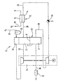
- the only figure shows a block diagram of a fuel cell system according to the invention.
- the fuel cell system 10 shown in the figure includes a fuel cell 12 with a cathode 14 and an anode 16.
- a fuel cell 12 with a cathode 14 and an anode 16.
- anode 16 For better clarity of presentation is in the Figure shows only one fuel cell 12 - in practice it is one by stacking several Fuel cell formed fuel cell block.
- the anode 16 of the fuel cell 12 is supplied with hydrogen H 2 or a hydrogen-containing gas (reformate) via a line 18.
- the cathode 14 of the fuel cell 12 is supplied with intake air containing oxygen O 2 via a line 20.
- the intake air passes through an air filter 22 and a compressor of a compressor expander unit 24 before it is fed to the cathode 14 of the fuel cell 12.
- the fuel cell system 10 further includes one rotatable adsorber 28 (rotor adsorber) arranged in this way is that it has a section in the supply air flow 20 and with another section in an exhaust air stream 30 the Fuel cell 12 is located.
- the axis of rotation D of the rotor adsorber is such between supply air flow 20 and exhaust air flow 30 arranged that when the rotor adsorber 28 rotates in the sense of drawn arrow is always a section of the Rotor adsorbers 28 in the supply air flow 20 and another Section in the exhaust air stream 30 is located. This will be a Desorption area 21 in the supply air flow and an adsorption area 31 defined in the exhaust air stream 30.
- the exhaust air from the cathode 14 of the fuel cell 12 is along a line 30 through an expander of the compressor-expander unit 24 the adsorption area 31 of the rotor adsorber 28 and then fed to a silencer 32.
- a silencer 32 In the exhaust pipe 30 can, as shown in the figure, one of the compressor expander unit 24 upstream condensate drain 34 be provided, which is already the part of the exhaust air in the cathode separates moisture contained in the form of mist droplets. Likewise, one can immediately before the adsorber enters Condensate drain can be arranged.
- the condensate drain 34 can also serve to part of the to recycle the recycled water content liquid because due to the increased humidity of the supply air in front of the cathode 14 of the fuel cell 12 the proportion of in the form of Mist droplets contained moisture will be greater.
- additional condensate drain with or without additional Heat exchanger (cooler) in front of or behind the fuel cell 12 conceivable.
- the remaining moisture in the exhaust air is in the Adsorption region 31 of the rotor adsorber 28 adsorbed.
- the adsorbed water is rotated in the sense of drawn arrow in the desorption region 21 of the Rotoradsorbers 28 rotated and there by no closer energy supply shown, for example in the form of Hot air, desorbed and directly into the supply air flow 20 Humidification of the supply air added.
- the Adsorption of water from the exhaust air flow from the fuel cell at a low pressure level immediately before leaving the Fuel cell system 10.
- the Adsorption also take place before the expander.
- a The fuel cell system according to the invention is desorbed with the help of after passing through the air compressor Compressor expander unit heated supply air flow before Entry into the cathode compartment of the fuel cell.
- desorption by the supply air flow also take place in front of the compressor.
- the serving as adsorbent Solid introduced into the rotor adsorber can, as in the illustrated embodiment possible after the desorption cooled by the intake air in a cooling unit 26 are rotated before it is again in the adsorption region 31 becomes.
- suitable absorbents for use in a Fuel cell systems according to the invention are in particular Silica gel and hydrophilic zeolites are suitable, but also other solids with a large inner surface are usable.
- the adsorbents can be in one Particle bed as well as in the form of ordered structures (Monolith structures, wikkeladsorber) can be used. in the the latter case is an application of the adsorbent to a Carrier material or a use of the homogeneous substance possible in one piece.
- the heat capacity of the solid in particular Adsorbent can be compared to its sorption capacity Add an inert substance so that a energy-optimized desorption through heat recovery good adsorption and desorption is achieved at the same time.
- the Adding the inert substance can take the form of a separate Layer or by mixing with the adsorbent.
- the invention is not based on the illustrated embodiment with a rotor adsorber limited. Rather, it is also designed as a fixed bed adsorption system possible one or more fixed beds includes, to which the supply or exhaust air flow each cyclically can be switched.
- the inventive Fuel cell system can recover water in the Fuel cell system in the sense of a water balance adjustment can be used in a variety of ways.
- it can recovered water in vapor or liquid at least partly for steam reforming gaseous or liquid Energy source, for high or low temperature shift reaction gaseous or liquid energy source or for autothermal Reforming gaseous or liquid energy sources be used.
- DMFC systems Use as make-up water for the liquid energy source Methanol-water mixture possible.
Landscapes
- Life Sciences & Earth Sciences (AREA)
- Engineering & Computer Science (AREA)
- Manufacturing & Machinery (AREA)
- Sustainable Development (AREA)
- Sustainable Energy (AREA)
- Chemical & Material Sciences (AREA)
- Chemical Kinetics & Catalysis (AREA)
- Electrochemistry (AREA)
- General Chemical & Material Sciences (AREA)
- Fuel Cell (AREA)
Abstract
Description
Claims (18)
- Verfahren zum Betrieb eines Brennstoffzellensystems, das mindestens eine Brennstoffzelle (12) umfaßt,
dadurch gekennzeichnet,
daß in einem Abluftstrom (30) der mindestens einen Brennstoffzelle (12) enthaltene Feuchtigkeit mittels Adsorption (31) dem Abluftstrom (30) entzogen, das adsorbierte Wasser desorbiert (21) und in den Zuluftstrom (20) und/oder den Brennstoffstrom und/oder in den Flüssigkeitsstrom der Anodenseite und/oder in den Kühlwasserkreislauf der mindestens einen Brennstoffzelle (12) zurückgeführt wird. - Verfahren nach Anspruch 1, dadurch gekennzeichnet, daß als mindestens eine Brennstoffzelle (12) eine PEM-Brennstoffzelle eingesetzt wird.
- Verfahren nach Anspruch 1 oder 2, dadurch gekennzeichnet, daß das desorbierte Wasser dampfförmig oder flüssig rückgeführt wird.
- Verfahren nach einem der Ansprüche 1 bis 3, dadurch gekennzeichnet, daß das adsorbierte Wasser mittels für die mindestens eine Brennstoffzelle (12) vorgesehener erhitzter Zuluft desorbiert (21) wird.
- Verfahren nach einem der Ansprüche 1 bis 4, dadurch gekennzeichnet, daß für die Adsorption (31) ein Adsorbens verwendet wird, das in homogener Schüttung vorliegt, das auf einem Trägermaterial aufgebracht ist oder das in einer geordneten Struktur als homogener Stoff vorliegt.
- Verfahren nach einem der Ansprüche 1 bis 5, dadurch gekennzeichnet, daß für die Adsorption (31) ein Adsorbens verwendet wird, das zwischen Adsorption und Desorption kontinuierlich oder getaktet rotierend angeordnet ist.
- Verfahren nach einem der Ansprüche 1 bis 5, dadurch gekennzeichnet, daß die Adsorption (31) bzw. Desorption (21) in mindestens einem Festbett erfolgt, dessen Zu- und Abluftströme zyklisch umgeschaltet werden.
- Verfahren nach Anspruch 6 oder 7, dadurch gekennzeichnet, daß das Adsorbens nach der Desorption gekühlt wird.
- Verfahren nach Anspruch 8, dadurch gekennzeichnet, daß zur Kühlung Ansaugluft verwendet wird.
- Brennstoffzellensystem mit mindestens einer Brennstoffzelle (12), dadurch gekennzeichnet, daß eine Rückgewinnung von in einem Abluftstrom (30) der mindestens einen Brennstoffzelle (12) enthaltener Feuchtigkeit mittels Adsorption (31), anschließender Desorption (21) adsorbierten Wassers und Rückführung in den Zuluftstrom (20) und/oder den Brennstoffstrom und/oder in den Flüssigkeitsstrom der Anodenseite und/oder in den Kühlwasserkreislauf der mindestens einen Brennstoffzelle (12) erfolgt.
- Brennstoffzellensystem nach Anspruch 10, dadurch gekennzeichnet, daß die mindestens eine Brennstoffzelle (12) eine PEM-Brennstoffzelle ist.
- Brennstoffzellensystem nach Anspruch 10 oder 11, dadurch gekennzeichnet, daß die Rückfuhr des desorbierten Wassers dampfförmig oder flüssig erfolgt.
- Brennstoffzellensystem nach einem der Ansprüche 10 bis 12, dadurch gekennzeichnet, daß die Desorption (21) des adsorbierten Wassers mittels für die mindestens eine Brennstoffzelle (12) vorgesehener erhitzter Zuluft erfolgt.
- Brennstoffzellensystem nach einem der Ansprüche 10 bis 13, dadurch gekennzeichnet, daß die Adsorption (31) mittels eines Adsorbens erfolgt, das in homogener Schüttung vorliegt, das auf einem Trägermaterial aufgebracht ist oder das in einer geordneten Struktur als homogener Stoff vorliegt.
- Brennstoffzellensystem nach einem der Ansprüche 10 bis 14, dadurch gekennzeichnet, daß die Adsorption (31) mittels eines Adsorbens erfolgt, das zwischen Adsorption und Desorption kontinuierlich oder getaktet rotierend angeordnet ist.
- Brennstoffzellensystem nach einem der Ansprüche 10 bis 14, dadurch gekennzeichnet, daß die Adsorption (31) bzw. Desorption (21) in mindestens einem Festbett erfolgt, dessen Zu- und Abluftströme zyklisch umgeschaltet werden.
- Brennstoffzellensystem nach Anspruch 15 oder 16, dadurch gekennzeichnet, daß nach der Desorption eine Kühlung des Adsorbens erfolgt.
- Brennstoffzellensystem nach Anspruch 17, dadurch gekennzeichnet, daß die Kühlung mittels der Ansaugluft erfolgt.
Applications Claiming Priority (2)
| Application Number | Priority Date | Filing Date | Title |
|---|---|---|---|
| DE19902219 | 1999-01-21 | ||
| DE19902219A DE19902219C1 (de) | 1999-01-21 | 1999-01-21 | Verfahren zum Betrieb eines Brennstoffzellensystems und Brennstoffzellensystem |
Publications (3)
| Publication Number | Publication Date |
|---|---|
| EP1022796A2 true EP1022796A2 (de) | 2000-07-26 |
| EP1022796A3 EP1022796A3 (de) | 2004-07-28 |
| EP1022796B1 EP1022796B1 (de) | 2006-06-21 |
Family
ID=7894907
Family Applications (1)
| Application Number | Title | Priority Date | Filing Date |
|---|---|---|---|
| EP99122279A Expired - Lifetime EP1022796B1 (de) | 1999-01-21 | 1999-11-09 | Verfahren zum Betrieb eines Brennstoffzellensystems und Brennstoffzellensystem |
Country Status (2)
| Country | Link |
|---|---|
| EP (1) | EP1022796B1 (de) |
| DE (2) | DE19902219C1 (de) |
Cited By (4)
| Publication number | Priority date | Publication date | Assignee | Title |
|---|---|---|---|---|
| WO2000063990A3 (de) * | 1999-04-19 | 2001-04-05 | Mannesmann Ag | Vorrichtung und verfahren zur befeuchtung einer brennstoffzellenmembran, sowie brennstoffzelle |
| EP1099269A4 (de) * | 1998-06-03 | 2001-09-26 | Int Fuel Cells Corp | Brennstoffzellenanlage mit direktem masse- und wärmetransport |
| DE102008007024A1 (de) | 2008-01-31 | 2009-08-06 | Fraunhofer-Gesellschaft zur Förderung der angewandten Forschung e.V. | Brennstoffzellensystem mit Adsorptionswärmespeicher |
| KR101117633B1 (ko) | 2004-06-30 | 2012-02-29 | 삼성에스디아이 주식회사 | 연료전지용 일산화탄소 흡착제, 연료전지용 일산화탄소정화기, 연료전지 시스템 및 일산화탄소 흡착제를 이용한일산화탄소 제거방법 |
Families Citing this family (10)
| Publication number | Priority date | Publication date | Assignee | Title |
|---|---|---|---|---|
| US6485854B1 (en) * | 2000-10-19 | 2002-11-26 | General Motors Corporation | Gas-liquid separator for fuel cell system |
| DE10065306A1 (de) * | 2000-12-29 | 2002-07-18 | Siemens Ag | Verfahren zum Betrieb einer in einem Fahrzeug verwendbaren Brennstoffzellenanlage und zugehörige Brennstoffzellenanlage |
| US6727016B2 (en) * | 2001-08-09 | 2004-04-27 | Motorola, Inc. | Direct methanol fuel cell including a water recovery and re-circulation system and method of fabrication |
| DE10212872A1 (de) * | 2002-03-22 | 2003-10-02 | Volkswagen Ag | Verfahren zum einstellbaren Kühlen eines Betriebsmediumstroms in einem Wärmetauscher, entsprechender Wärmetauscher und entsprechendes Brennstoffzellensystem |
| US7018732B2 (en) | 2002-04-15 | 2006-03-28 | Hydrogenics Corporation | System and method for management of gas and water in fuel cell system |
| DE10230283A1 (de) * | 2002-07-05 | 2004-01-29 | Daimlerchrysler Ag | Verfahren und Anordnung zum Reinigen der einer Brennstoffzelle für den Betrieb zuzuführenden Gase von Bestandteilen, die für den Brennstoffzellenbetrieb ungünstig sind |
| EP1543576A2 (de) * | 2002-09-23 | 2005-06-22 | Hydrogenics Corporation | System und methode zur verwaltung von gas und wasser in brennstoffzellensystem |
| JP2004342372A (ja) | 2003-05-13 | 2004-12-02 | Toyota Motor Corp | 燃料電池システム及びこれを搭載した車両 |
| DE102009010594A1 (de) * | 2009-02-25 | 2010-08-26 | Enymotion Gmbh | Brennstoffzellensystem und Verfahren zum Anfahren und Betrieb eines solchen Brennstoffzellensystems |
| DE102016213836A1 (de) * | 2016-07-27 | 2018-02-01 | Bayerische Motoren Werke Aktiengesellschaft | Verfahren zum Beheizen eines Wasserabscheiders sowie Wasserabscheider für ein Brennstoffzellensystem eines Kraftfahrzeugs |
Family Cites Families (6)
| Publication number | Priority date | Publication date | Assignee | Title |
|---|---|---|---|---|
| US5250368A (en) * | 1992-11-19 | 1993-10-05 | Ergenics, Inc. | Extended cycle-life metal hydride battery for electric vehicles |
| US5360679A (en) * | 1993-08-20 | 1994-11-01 | Ballard Power Systems Inc. | Hydrocarbon fueled solid polymer fuel cell electric power generation system |
| DE19704888A1 (de) * | 1997-02-10 | 1998-08-13 | Bhf Verfahrenstechnik Gmbh | Verfahren zum Betrieb eines Heizkessels mit Brennwertnutzung und Heizkessel zur Realisierung des Verfahrens |
| US6013385A (en) * | 1997-07-25 | 2000-01-11 | Emprise Corporation | Fuel cell gas management system |
| US5935726A (en) * | 1997-12-01 | 1999-08-10 | Ballard Power Systems Inc. | Method and apparatus for distributing water to an ion-exchange membrane in a fuel cell |
| US6007931A (en) * | 1998-06-24 | 1999-12-28 | International Fuel Cells Corporation | Mass and heat recovery system for a fuel cell power plant |
-
1999
- 1999-01-21 DE DE19902219A patent/DE19902219C1/de not_active Expired - Fee Related
- 1999-11-09 EP EP99122279A patent/EP1022796B1/de not_active Expired - Lifetime
- 1999-11-09 DE DE59913594T patent/DE59913594D1/de not_active Expired - Lifetime
Cited By (4)
| Publication number | Priority date | Publication date | Assignee | Title |
|---|---|---|---|---|
| EP1099269A4 (de) * | 1998-06-03 | 2001-09-26 | Int Fuel Cells Corp | Brennstoffzellenanlage mit direktem masse- und wärmetransport |
| WO2000063990A3 (de) * | 1999-04-19 | 2001-04-05 | Mannesmann Ag | Vorrichtung und verfahren zur befeuchtung einer brennstoffzellenmembran, sowie brennstoffzelle |
| KR101117633B1 (ko) | 2004-06-30 | 2012-02-29 | 삼성에스디아이 주식회사 | 연료전지용 일산화탄소 흡착제, 연료전지용 일산화탄소정화기, 연료전지 시스템 및 일산화탄소 흡착제를 이용한일산화탄소 제거방법 |
| DE102008007024A1 (de) | 2008-01-31 | 2009-08-06 | Fraunhofer-Gesellschaft zur Förderung der angewandten Forschung e.V. | Brennstoffzellensystem mit Adsorptionswärmespeicher |
Also Published As
| Publication number | Publication date |
|---|---|
| EP1022796A3 (de) | 2004-07-28 |
| DE59913594D1 (de) | 2006-08-03 |
| DE19902219C1 (de) | 2000-06-08 |
| EP1022796B1 (de) | 2006-06-21 |
Similar Documents
| Publication | Publication Date | Title |
|---|---|---|
| DE19902219C1 (de) | Verfahren zum Betrieb eines Brennstoffzellensystems und Brennstoffzellensystem | |
| DE69931171T2 (de) | Stromerzeugungssystem | |
| DE10204845A1 (de) | Kohlenmonoxidadsorption zur Kohlenmonoxidreinigung in einem Brennstoffzellensystem | |
| WO2009059571A1 (de) | Hochtemperaturbrennstoffzellensystem mit teilweisem kreislauf des anodenabgases und ausschleusung von gaskomponenten | |
| DE69915632T2 (de) | Brennstoffzellenanlage mit direktem masse- und wärmetransport | |
| DE102009051476A1 (de) | Brennstoffzellensystem mit wenigstens einer Brennstoffzelle | |
| DE102014211847A1 (de) | Brennstoffzellensystem | |
| DE10034399A1 (de) | Brennstoffzellensystem mit Einrichtung zur Wasserrückgewinnung und Verfahren zum Betrieb eines solchen | |
| DE102015117055B4 (de) | Stapelgehäuse-Belüftung, Brennstoffzellensystem sowie Fahrzeug | |
| DE19943059B4 (de) | System zur Auskondensation einer Flüssigkeit aus einem Gasstrom | |
| DE102004017281B4 (de) | Brennstoffzellen-System und Verwendung eines Brennstoffzellen-Systems in einem Fahrzeug | |
| WO2011020560A1 (de) | Verfahren und vorrichtung zur erzeugung elektrischer energie | |
| DE602004000440T2 (de) | Brennstoffzellen-Antriebseinheit für ein Kraftfahrzeug und Verfahren zum Auftauen einer Brennstoffzelle | |
| DE102019205811A1 (de) | Befeuchtermodul, Befeuchter, Brennstoffzellensystem mit einem solchen, sowie Verfahren zur Befeuchtung eines Gases | |
| EP2399314A1 (de) | Brennstoffzellensystem mit wenigstens einer brennstoffzelle | |
| DE102020102398A1 (de) | Verfahren zur Regeneration einer Brennstoffzellenvorrichtung sowie eine Brennstoffzellenvorrichtung und ein Kraftfahrzeug mit einer Brennstoffzellenvorrichtung | |
| DE102010041465B4 (de) | Brennstoffzellensystem mit Direktmethanolbrennstoffzelle und Verfahren zu dessen Betrieb | |
| WO2017072000A1 (de) | Kathodenversorgung für eine mehrfach-brennstoffzelle sowie verfahren zum versorgen von teilbrennstoffzellen mit einem kathoden-betriebsmedium | |
| DE102019212086A1 (de) | Brennstoffzellenvorrichtung | |
| DE102023122241B3 (de) | Brennstoffzellenstapel, Brennstoffzellenvorrichtung sowie Brennstoffzellenfahrzeug | |
| DE102020102390A1 (de) | Brennstoffzelle und Brennstoffzellensystem | |
| DE102021118977B3 (de) | Festoxidbrennstoffzellenvorrichtung mit einer Wasserentzugseinheit für das Anodenabgas | |
| DE102019211589A1 (de) | Befeuchter, Brennstoffzellenvorrichtung mit Befeuchter sowie Kraftfahrzeug | |
| DE102019126308A1 (de) | Befeuchter, Brennstoffzellenvorrichtung sowie Kraftfahrzeug mit einer Brennstoffzellenvorrichtung | |
| DE10232757A1 (de) | Vorrichtung und Verfahren zur Befeuchtung eines Gasstroms |
Legal Events
| Date | Code | Title | Description |
|---|---|---|---|
| PUAI | Public reference made under article 153(3) epc to a published international application that has entered the european phase |
Free format text: ORIGINAL CODE: 0009012 |
|
| AK | Designated contracting states |
Kind code of ref document: A2 Designated state(s): AT BE CH CY DE DK ES FI FR GB GR IE IT LI LU MC NL PT SE |
|
| AX | Request for extension of the european patent |
Free format text: AL;LT;LV;MK;RO;SI |
|
| PUAL | Search report despatched |
Free format text: ORIGINAL CODE: 0009013 |
|
| AK | Designated contracting states |
Kind code of ref document: A3 Designated state(s): AT BE CH CY DE DK ES FI FR GB GR IE IT LI LU MC NL PT SE |
|
| AX | Request for extension of the european patent |
Extension state: AL LT LV MK RO SI |
|
| 17P | Request for examination filed |
Effective date: 20040816 |
|
| 17Q | First examination report despatched |
Effective date: 20041118 |
|
| AKX | Designation fees paid |
Designated state(s): DE FR GB IT |
|
| GRAP | Despatch of communication of intention to grant a patent |
Free format text: ORIGINAL CODE: EPIDOSNIGR1 |
|
| GRAS | Grant fee paid |
Free format text: ORIGINAL CODE: EPIDOSNIGR3 |
|
| GRAA | (expected) grant |
Free format text: ORIGINAL CODE: 0009210 |
|
| AK | Designated contracting states |
Kind code of ref document: B1 Designated state(s): DE FR GB IT |
|
| PG25 | Lapsed in a contracting state [announced via postgrant information from national office to epo] |
Ref country code: IT Free format text: LAPSE BECAUSE OF FAILURE TO SUBMIT A TRANSLATION OF THE DESCRIPTION OR TO PAY THE FEE WITHIN THE PRESCRIBED TIME-LIMIT;WARNING: LAPSES OF ITALIAN PATENTS WITH EFFECTIVE DATE BEFORE 2007 MAY HAVE OCCURRED AT ANY TIME BEFORE 2007. THE CORRECT EFFECTIVE DATE MAY BE DIFFERENT FROM THE ONE RECORDED. Effective date: 20060621 |
|
| REG | Reference to a national code |
Ref country code: GB Ref legal event code: FG4D Free format text: NOT ENGLISH |
|
| REF | Corresponds to: |
Ref document number: 59913594 Country of ref document: DE Date of ref document: 20060803 Kind code of ref document: P |
|
| GBT | Gb: translation of ep patent filed (gb section 77(6)(a)/1977) |
Effective date: 20060928 |
|
| ET | Fr: translation filed | ||
| PLBE | No opposition filed within time limit |
Free format text: ORIGINAL CODE: 0009261 |
|
| STAA | Information on the status of an ep patent application or granted ep patent |
Free format text: STATUS: NO OPPOSITION FILED WITHIN TIME LIMIT |
|
| RAP2 | Party data changed (patent owner data changed or rights of a patent transferred) |
Owner name: DAIMLERCHRYSLER AG |
|
| 26N | No opposition filed |
Effective date: 20070322 |
|
| REG | Reference to a national code |
Ref country code: FR Ref legal event code: CD |
|
| PGFP | Annual fee paid to national office [announced via postgrant information from national office to epo] |
Ref country code: FR Payment date: 20100603 Year of fee payment: 11 |
|
| PGFP | Annual fee paid to national office [announced via postgrant information from national office to epo] |
Ref country code: DE Payment date: 20100511 Year of fee payment: 11 |
|
| PGFP | Annual fee paid to national office [announced via postgrant information from national office to epo] |
Ref country code: GB Payment date: 20100423 Year of fee payment: 11 |
|
| GBPC | Gb: european patent ceased through non-payment of renewal fee |
Effective date: 20101109 |
|
| REG | Reference to a national code |
Ref country code: DE Ref legal event code: R119 Ref document number: 59913594 Country of ref document: DE Effective date: 20110601 Ref country code: DE Ref legal event code: R119 Ref document number: 59913594 Country of ref document: DE Effective date: 20110531 |
|
| REG | Reference to a national code |
Ref country code: FR Ref legal event code: ST Effective date: 20110801 |
|
| PG25 | Lapsed in a contracting state [announced via postgrant information from national office to epo] |
Ref country code: DE Free format text: LAPSE BECAUSE OF NON-PAYMENT OF DUE FEES Effective date: 20110531 |
|
| PG25 | Lapsed in a contracting state [announced via postgrant information from national office to epo] |
Ref country code: FR Free format text: LAPSE BECAUSE OF NON-PAYMENT OF DUE FEES Effective date: 20101130 |
|
| PG25 | Lapsed in a contracting state [announced via postgrant information from national office to epo] |
Ref country code: GB Free format text: LAPSE BECAUSE OF NON-PAYMENT OF DUE FEES Effective date: 20101109 |