EP1022832B1 - Dispositif de maintien pour cable traversant un mur de manière étanche - Google Patents
Dispositif de maintien pour cable traversant un mur de manière étanche Download PDFInfo
- Publication number
- EP1022832B1 EP1022832B1 EP99121769A EP99121769A EP1022832B1 EP 1022832 B1 EP1022832 B1 EP 1022832B1 EP 99121769 A EP99121769 A EP 99121769A EP 99121769 A EP99121769 A EP 99121769A EP 1022832 B1 EP1022832 B1 EP 1022832B1
- Authority
- EP
- European Patent Office
- Prior art keywords
- retaining
- cable
- holes
- plate
- retaining device
- Prior art date
- Legal status (The legal status is an assumption and is not a legal conclusion. Google has not performed a legal analysis and makes no representation as to the accuracy of the status listed.)
- Expired - Lifetime
Links
- 238000007789 sealing Methods 0.000 claims abstract description 34
- 230000009975 flexible effect Effects 0.000 claims description 17
- 229920001084 poly(chloroprene) Polymers 0.000 claims description 3
- 210000002105 tongue Anatomy 0.000 abstract description 29
- 238000004519 manufacturing process Methods 0.000 description 2
- 239000000463 material Substances 0.000 description 2
- 230000035515 penetration Effects 0.000 description 2
- 230000001419 dependent effect Effects 0.000 description 1
- 230000000694 effects Effects 0.000 description 1
- 210000004907 gland Anatomy 0.000 description 1
- 230000037431 insertion Effects 0.000 description 1
- 238000003780 insertion Methods 0.000 description 1
- 239000002184 metal Substances 0.000 description 1
- 230000000149 penetrating effect Effects 0.000 description 1
- 229920003023 plastic Polymers 0.000 description 1
Images
Classifications
-
- H—ELECTRICITY
- H02—GENERATION; CONVERSION OR DISTRIBUTION OF ELECTRIC POWER
- H02G—INSTALLATION OF ELECTRIC CABLES OR LINES, OR OF COMBINED OPTICAL AND ELECTRIC CABLES OR LINES
- H02G3/00—Installations of electric cables or lines or protective tubing therefor in or on buildings, equivalent structures or vehicles
- H02G3/02—Details
- H02G3/08—Distribution boxes; Connection or junction boxes
- H02G3/088—Dustproof, splashproof, drip-proof, waterproof, or flameproof casings or inlets
Definitions
- the invention relates to a holding device for sealingly guided through walls by cables, having a plurality of cable through-holes, mounted on the likewise provided with cable through-holes wall mounting plate and with an elastic, in the assembled state between the holding plate and the wall arranged sealing plate, the aligned has cable penetration holes prefabricated to the cable through holes.
- an elastic plate between a retaining plate and a counter-holding plate is arranged, these three plates are fixed by means of a flange on a wall. After sealingly penetrating a cable, it is slightly withdrawn so that the region surrounding the cable of the elastic plate is drawn into the smaller diameter through hole of the retaining plate and jammed there. This leads to desired cable strain relief and at the same time for sealing the cable gland.
- the disadvantage of the known holding device is firstly that the strain relief is effective only at a very specific cable diameter, so that a very complicated arrangement with an exact adjustment of the through holes to the respective cable diameter is required for cables with different diameters. In a once mounted holding device, only the originally provided cable can be used. Another disadvantage is that after the jamming, a pulling back of the cable to the rear is no longer possible, for example in the case of an erroneously inserted cable. Finally, the known holding device is complicated and cumbersome to manufacture and assemble due to the large number of plates required, which also entails cost disadvantages.
- An object of the present invention is to provide a simpler holding device of the type mentioned, in which can be used in each through hole cables with different diameters and kept safe with good seal.
- the elastic retaining tongues ensure a good strain relief, wherein the deflection towards the wall is different for different cable diameters, but in each case a locking is ensured under tensile stress. Since the deflection remains towards the wall, the retaining tongues form practically oblique supporting pillars, which counteract a strain relief.
- Another advantage of the elastic retaining tongues is that they can be unlocked in a simple manner, so that a retraction of the respective cable and pulling out of the respective cable through-hole are possible in a simple manner. Since the unlocking can be done from the front, while disassembly of the fixture is not required.
- the retaining tongues according to the invention also make it possible to securely hold different cross-sectional shapes of cables.
- the holding device practically consists of only two components, namely the holding plate and the sealing plate.
- the holding plate can have virtually any shape and thickness.
- a particularly good strain relief and a particularly secure hold of the cable are ensured by the fact that the free ends of the retaining tongues are formed like a blade or at least have a tip.
- the retaining tongues are integrally connected thereto and are formed in particular by two slots in the retaining plate.
- the retaining tongues advantageously have a smaller thickness than the substantially rigid retaining plate.
- the retaining tongues are preferably connected to the side facing away from the sealing plate side of the retaining plate with this, so that a deflection into the respective cable through holes is possible without the sealing plate would be affected.
- the cable penetration points are formed in an advantageous manner blind hole, so that a good introduction of the respective cable and a relatively easy piercing of the bottom portion are possible.
- This floor area then forms a sealing around the cable to this.
- each through hole is associated with a holding tongue.
- the retaining plate and the sealing plate preferably have mutually aligned mounting holes, so that the retaining plate can be fixed by means of screws on the wall, wherein the sealing plate is sandwiched therebetween.
- a particularly cost-effective solution is also that the flexible sealing plate as a part of a cut-to-length is formed flexible bands, so that any differently long holding plates can be provided in a simple manner by cutting this tape with a matching sealing plate.
- each retaining plate has at opposite boundary lines toothing elements for toothed juxtaposition.
- the opposite boundary lines are expediently designed so that there is a constant hole spacing of the cable through-holes in the longitudinal direction in juxtaposed holding plates. This allows the use of cut-to-length sections of a flexible band as sealing plates.
- the retaining plate may be provided with cable through-holes of different diameters and / or different shape in order to hold very different cables can.
- a particularly good sealing effect results from the use of neoprene as the material for the gasket plate.
- a pin-like tool is provided in an advantageous manner, with the only the respective retaining tongue inwards must be pressed.
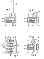
- the holding device shown in FIGS. 1 to 4 as a first embodiment consists of a substantially rigid plate 10 made of metal or plastic udn a sealing plate 11 made of an elastic, flexible material, such as neoprene, the substantially has the same outer contour. At the four corner areas have the substantially rectangular plates 10, 11 mounting holes 12, so that the holding plate 10 can be screwed by means not shown fastening screws to a wall, not shown, that the sealing plate 11 is sealingly therebetween.
- This wall may be, for example, a control cabinet, a housing, a junction box or the like, wherein the holding device can be used wherever a sealing passage of cables through a wall with simultaneous strain relief is required.
- the holding plate 10 has eight cable through-holes 13, which are arranged in two rows and each aligned with blind holes 14 in the seal plate 11.
- Eight retaining tongues 15 are integrally connected to the retaining plate 10 so that their free ends engage each in the cable through-holes 13 something.
- These retaining tongues 15 are arranged parallel to each other, wherein the free ends each have alternately in opposite directions and thereby alternately engage in a cable through hole 13 of one and the other row.
- the retaining tongues 15 are formed by introducing corresponding parallel slots 16 in the holding plate 10. From Fig. 1 it can be seen that the thickness of the retaining tongues 15 is substantially smaller than the thickness of the retaining plate 10 to the required To achieve elasticity and flexibility of the retaining tongues 15.
- the one-piece connection of the retaining tongues 15 with the holding plate 10 takes place on the side facing away from the sealing plate 11 side, so that a deflection of the retaining tongues 15 to the sealing plate 11 is possible out without affecting them.
- the free ends of the retaining tongues 15 are formed in the manner of cutting 17 in order to ensure a particularly good clawing with a cable 18.
- the cutting edges 17 are part-circular shaped and thus adapted to the outer circumference of a cable 18 designed as a round cable. Instead of cutting-like free ends, they can also have one or more tips.
- the cable 18 is inserted into a cable through hole 13, whereby the engaging in this cable through hole 13 retaining tab 15 is deflected to the sealing plate 11 out.
- the cable 18 then pierces the thin bottom portion 19 of the blind hole 14, this bottom portion 19 then sealingly around the cable 18, as shown in Figs. 3 and 4.
- Fig. 3 shows the cable 18 in the inserted or retracted state.
- the retaining tongue 15 and the blade-like free end region barbs like the barbed 18, so that a very good strain relief is achieved.
- the retaining tongue 15 acts at a strain relief as an inclined counter-support.
- the retaining tongue 15 is pressed inwardly as shown in FIG. 4 by means of a pin-like tool 20, so that an unlocking occurs and the cable 18 can be easily pulled out. Due to the thin bottom portions 19, which close the blind holes 14, unused cable through holes 13 are automatically sealed.
- the holding tongues 15 are deflected more or less depending on the diameter to the sealing plate 11, so that in the illustrated embodiment, cables with diameters between about 5 - 8 mm can be kept safe. If cables with diameters are also to be kept outside this range, cable through-holes 13 with different diameters can also be provided in a holding plate 10. Number, arrangement and shape of the cable through-holes 13 are basically variable. Thus, for example, embodiments for flat cables can be realized, wherein, depending on requirements, a plurality of retaining tongues 15 per cable through-hole 13 can be provided.
- the thickness of retaining plate 10 and sealing plate 11 can also vary within wide limits. For example, compared to the first embodiment substantially thinner sealing plate 11 can be used.
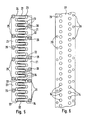
- FIGS. 5 and 6 largely corresponds to the first embodiment, and the same or equivalent components and areas are provided with the same reference numerals and not described again.
- four holding plates 21 are strung together, which largely correspond to the holding plate 10.
- the transverse to the row arrangement of the cable through holes 13 extending boundary lines 22 of the holding plates 21 are provided with projections 23 and recesses 24 that when teeth are joined together, a toothing.
- the boundary lines 22 are arranged so that a constant hole spacing between the cable through holes 13 is formed.
- Fixing holes 25 are arranged in such a way across the lines in the region of the abutting boundary lines 22 that the corresponding retaining screws, not shown, each overlap and fix both adjoining support plates 21.
- fastening holes 26 are still arranged in the central regions.
- an elastic, flexible band 27 which has two rows of blind holes 28, whose distances from each other and within the flexible band 27 corresponds to those of the cable through holes 13 of the juxtaposed holding plates 21. Furthermore, mounting holes 29 are provided, which also correspond to the mounting holes 25, 26 of the juxtaposed holding plates 21.
- sealing plates can be formed according to the length arrangement of the juxtaposed holding plates 21, which also for individual holding plates 21 matching sealing plates can be cut off from this flexible band 27.
- the seal plate 11 of the first embodiment may be formed by, for example, cutting to length a corresponding flexible band.
- corresponding variations in the shape, arrangement and number of cable through-holes 13 are also possible in the second embodiment.
Landscapes
- Engineering & Computer Science (AREA)
- Architecture (AREA)
- Civil Engineering (AREA)
- Structural Engineering (AREA)
- Installation Of Indoor Wiring (AREA)
- Insertion, Bundling And Securing Of Wires For Electric Apparatuses (AREA)
- Laying Of Electric Cables Or Lines Outside (AREA)
Claims (15)
- Dispositif de retenue pour des câbles (18) amenés à traverser des parois de façon étanche, comprenant une plaque de retenue (10) présentant plusieurs trous de passage de câble (13) et pouvant être montée contre la paroi également munie d'ouvertures de passage de câble (13) et comprenant une plaque d'étanchéité élastique (11) disposée à l'état monté entre la plaque de retenue (10) et la paroi et présentant des points ruptibles de traversée de câble préformés en coïncidence avec les trous de passage de câble (13), caractérisé en ce que la plaque de retenue (10 ; 21) possède des languettes de retenue élastiques (15) s'engageant latéralement dans les trous de passage de câble (13) dont chacune, lorsque l'on fait passer un câble (18) à travers le trou de passage de câble correspondant (13), est déviée vers la paroi et, en cas de sollicitation en traction du câble (18), s'accroche à celui-ci dans la direction opposée, avec une déviation résiduelle vers la paroi.
- Dispositif de retenue selon la revendication 1, caractérisé en ce que les extrémités libres des languettes de retenue (15) sont réalisées à la manière de lames ou présentent au moins une pointe.
- Dispositif de retenue selon la revendication 1 ou 2, caractérisé en ce que les languettes de retenue (15) sont reliées d'une seule pièce à la plaque de retenue (10 ; 21) et sont réalisées chacune en particulier par deux fentes (16) dans la plaque de retenue.
- Dispositif de retenue selon l'une des revendications précédentes, caractérisé en ce que pour obtenir une élasticité de ressort, les languettes de retenue (15) possèdent une épaisseur inférieure à la plaque de retenue (10 ; 21) pour l'essentiel rigide.
- Dispositif de retenue selon la revendication 4, caractérisé en ce que sur le côté détourné de la plaque d'étanchéité (11) de la plaque de retenue (10 ; 21), les languettes de retenue (15) sont reliées à celle-ci.
- Dispositif de retenue selon l'une des revendications précédentes, caractérisé en ce que les points de traversée de câble (14) sont réalisés à la manières de trous borgnes.
- Dispositif de retenue selon l'une des revendications précédentes, caractérisé en ce qu'une languette de retenue (15) est affectée à chaque trou de passage de câble (13).
- Dispositif de retenue selon la revendication 7, caractérisé en ce que plusieurs languettes de retenue (15) sont disposées en parallèle les unes aux autres, leurs extrémités libres étant tournées respectivement en alternance dans des directions opposées et débouchant sur des trous de passage de câble (13) qui sont disposés sur deux rangées parallèles.
- Dispositif de retenue selon l'une des revendications précédentes, caractérisé en ce que la plaque de retenue (10) et la plaque d'étanchéité (11) possèdent des trous de fixation (12; 25, 26, 29) en coïncidence les uns avec les autres.
- Dispositif de retenue selon l'une des revendications précédentes, caractérisé en ce que la plaque d'étanchéité flexible (11) est réalisée comme une partie d'une bande flexible à tronçonner (27).
- Dispositif de retenue selon l'une des revendications précédentes, caractérisé en ce que la plaque de retenue (21) possède des éléments à denture (23, 24) sur des lignes de délimitation opposées (22) pour mettre bout à bout au moyen des dentures plusieurs plaques de retenue (21).
- Dispositif de retenue selon la revendication 11, caractérisé en ce que les lignes de délimitation opposées (22) sont réalisées de telle sorte qu'il en résulte un espacement de trous constant des trous de passage de câble (13) dans la direction longitudinale lorsque des plaques de retenue (21) sont mises bout à bout.
- Dispositif de retenue selon l'une des revendications précédentes, caractérisé en ce que la plaque de retenue est pourvue de trous de passage de câble de différents diamètres et/ou de différentes formes.
- Dispositif de retenue selon l'une des revendications précédentes, caractérisé en ce que la plaque d'étanchéité (11) se compose de néoprène.
- Dispositif de retenue selon l'une des revendications précédentes, caractérisé en ce qu'un outil de type broche (20) est prévu pour détacher les languettes de retenue (15) des câbles (18).
Applications Claiming Priority (2)
| Application Number | Priority Date | Filing Date | Title |
|---|---|---|---|
| DE19901914 | 1999-01-19 | ||
| DE19901914A DE19901914A1 (de) | 1999-01-19 | 1999-01-19 | Haltevorrichtung für durch Wandungen dichtend hindurchgeführte Kabel |
Publications (3)
| Publication Number | Publication Date |
|---|---|
| EP1022832A2 EP1022832A2 (fr) | 2000-07-26 |
| EP1022832A3 EP1022832A3 (fr) | 2001-03-14 |
| EP1022832B1 true EP1022832B1 (fr) | 2006-06-07 |
Family
ID=7894711
Family Applications (1)
| Application Number | Title | Priority Date | Filing Date |
|---|---|---|---|
| EP99121769A Expired - Lifetime EP1022832B1 (fr) | 1999-01-19 | 1999-11-03 | Dispositif de maintien pour cable traversant un mur de manière étanche |
Country Status (4)
| Country | Link |
|---|---|
| US (1) | US6259033B1 (fr) |
| EP (1) | EP1022832B1 (fr) |
| AT (1) | ATE329397T1 (fr) |
| DE (2) | DE19901914A1 (fr) |
Families Citing this family (16)
| Publication number | Priority date | Publication date | Assignee | Title |
|---|---|---|---|---|
| US6563050B2 (en) * | 2000-11-06 | 2003-05-13 | Adc Telecommunications, Inc. | Cable head assembly |
| DE20114120U1 (de) * | 2001-08-27 | 2003-01-23 | Compagnie Deutsch GmbH, 82152 Planegg | Zugentlastungsvorrichtung für ein elektrisches Kabel |
| US6764351B2 (en) * | 2001-08-27 | 2004-07-20 | Campagnie Deutsch GmbH | Electrical connector |
| JP3634301B2 (ja) * | 2001-11-16 | 2005-03-30 | 本田技研工業株式会社 | シール部材 |
| DE10162845C1 (de) * | 2001-12-01 | 2003-06-05 | Lumberg Connect Gmbh & Co Kg | Elektrischer Steckverbinder zum Anschluss an Leitungen mit einer Zugentlastung und Verfahren zur Konfektionierung eines solchen Steckverbinders |
| ES2394649T3 (es) | 2006-03-20 | 2013-02-04 | Beele Engineering B.V. | Sistema para sellar dinámicamente un manguito de canalización a través del cual se extiende un tubo o cable |
| SE531217C2 (sv) * | 2007-05-29 | 2009-01-20 | Roxtec Ab | Kabelgenomföring |
| US20080296061A1 (en) * | 2007-05-30 | 2008-12-04 | Kerr Jr Jack Russell | Connector for an electrical junction box |
| DE202009011431U1 (de) | 2009-08-25 | 2009-11-19 | Thomsen High-Tec Gmbh | Klemmkörper sowie ein Stanzwerkzeug zur Herstellung eines solchen Klemmkörpers |
| ES2392791T3 (es) | 2010-05-25 | 2012-12-13 | Beele Engineering B.V. | Un conjunto y un procedimiento para proporcionar un sistema de sellado en una abertura |
| JP5829559B2 (ja) * | 2012-03-21 | 2015-12-09 | 矢崎総業株式会社 | 電線保護構造 |
| JP5914160B2 (ja) * | 2012-05-22 | 2016-05-11 | 矢崎総業株式会社 | 電線保護カバー |
| EP2703705B1 (fr) | 2012-08-30 | 2017-03-29 | Beele Engineering B.V. | Système d'étanchéité pour un espace annulaire |
| NL2010304C2 (en) * | 2013-02-14 | 2014-08-18 | Beele Eng Bv | System for sealingly holding cables which extend through an opening. |
| US11510331B2 (en) * | 2020-09-10 | 2022-11-22 | Dell Products, L.P. | Profile-modeling cable clip for sealing airflow in an information handling system (IHS) chassis |
| CN217116634U (zh) * | 2022-03-14 | 2022-08-02 | 群创光电股份有限公司 | 电子装置 |
Family Cites Families (7)
| Publication number | Priority date | Publication date | Assignee | Title |
|---|---|---|---|---|
| US4316999A (en) * | 1980-07-23 | 1982-02-23 | Gte Sylvania Canada Limited | Electrical wiring box and cable clamp |
| US4605816A (en) * | 1985-02-19 | 1986-08-12 | Harvey Hubbell Incorporated | Molded outlet box with integral cable clamp |
| CA1295383C (fr) * | 1988-04-29 | 1992-02-04 | Robert W. Harrington | Connecteur de cables |
| DE3937192A1 (de) * | 1989-11-08 | 1991-05-16 | Bosch Gmbh Robert | Kabeldurchfuehrung |
| US5254808A (en) * | 1990-07-11 | 1993-10-19 | Thomas & Betts Corporation | Enclosure for an electrical terminal block including barrier means for a cable entry opening |
| CH688012A5 (de) * | 1996-07-31 | 1997-04-15 | Stunzi Industrieelektronik Gmb | Befestigungsvorrichtung fuer Rundkabel in Wandungen. |
| US6177633B1 (en) * | 1999-06-10 | 2001-01-23 | Arlington Industries, Inc. | Cable connector |
-
1999
- 1999-01-19 DE DE19901914A patent/DE19901914A1/de not_active Withdrawn
- 1999-11-03 EP EP99121769A patent/EP1022832B1/fr not_active Expired - Lifetime
- 1999-11-03 AT AT99121769T patent/ATE329397T1/de not_active IP Right Cessation
- 1999-11-03 DE DE59913521T patent/DE59913521D1/de not_active Expired - Lifetime
- 1999-12-17 US US09/465,610 patent/US6259033B1/en not_active Expired - Lifetime
Also Published As
| Publication number | Publication date |
|---|---|
| ATE329397T1 (de) | 2006-06-15 |
| DE19901914A1 (de) | 2000-07-20 |
| US6259033B1 (en) | 2001-07-10 |
| DE59913521D1 (de) | 2006-07-20 |
| EP1022832A3 (fr) | 2001-03-14 |
| EP1022832A2 (fr) | 2000-07-26 |
Similar Documents
| Publication | Publication Date | Title |
|---|---|---|
| EP1022832B1 (fr) | Dispositif de maintien pour cable traversant un mur de manière étanche | |
| DE4229279C2 (de) | Steckverbinder mit einer dualen Haltestruktur zum Haltern von Kontaktelementen | |
| DE2752117C2 (de) | Elektrisches Verbindergehäuse | |
| DE2317040A1 (de) | Schraubenlose anschluss- oder verbindungsklemme fuer elektrische leitungen | |
| DE2647235A1 (de) | Distanzhalter fuer durch schutzrohre hindurchgefuehrte rohre | |
| DD268553A5 (de) | Aderverbinder fuer kabeladern | |
| EP3224907B1 (fr) | Connecteur pour films de circuit imprimé flexibles | |
| DE3106645A1 (de) | Elektrisches verbindungsstueck | |
| DE20003081U1 (de) | Kabelhaltevorrichtung | |
| DE2903960B2 (de) | Vollisolierte Abzweigklemme | |
| EP2660939B1 (fr) | Dispositif de liaison de câble pour un câble | |
| DE9209519U1 (de) | HF-dichter Baugruppenträger | |
| DE202005013339U1 (de) | Rastaufnahmeelement und Rastverbindungssystem | |
| DE102018116356B3 (de) | Steckverbinder für flexible Leiterfolien | |
| DE4005351C2 (fr) | ||
| DE69700766T2 (de) | Elektrischer Verbinder zum Verbinden von elektrischen Leitungen | |
| EP2639910B1 (fr) | Boîtier encastrable pour canaux d'intégration d'appareil et canal d'intégration d'appareils doté de celui-ci | |
| DE19811476C1 (de) | Kabelklemme | |
| DE10010452A1 (de) | Dichtungskörper für längsgeteilte Kabelgarnituren | |
| DE3339313A1 (de) | Stecker fuer schwachstromanlagen | |
| DE19611719C2 (de) | Kontaktanordnung zum Herstellen einer Hochfrequenz-Dichtigkeit | |
| DE202019103487U1 (de) | Spreizbarer Eckwinkel | |
| CH688669A5 (de) | Zugentlastungsvorrichtung. | |
| DE202009016064U1 (de) | Kontaktelementanordnung sowie Anschlussvorrichtung für eine derartige Kontaktelementanordnung | |
| DE202017102320U1 (de) | Kabelhalter |
Legal Events
| Date | Code | Title | Description |
|---|---|---|---|
| PUAI | Public reference made under article 153(3) epc to a published international application that has entered the european phase |
Free format text: ORIGINAL CODE: 0009012 |
|
| AK | Designated contracting states |
Kind code of ref document: A2 Designated state(s): AT CH DE FR GB IT LI |
|
| AX | Request for extension of the european patent |
Free format text: AL;LT;LV;MK;RO;SI |
|
| PUAL | Search report despatched |
Free format text: ORIGINAL CODE: 0009013 |
|
| AK | Designated contracting states |
Kind code of ref document: A3 Designated state(s): AT BE CH CY DE DK ES FI FR GB GR IE IT LI LU MC NL PT SE |
|
| AX | Request for extension of the european patent |
Free format text: AL;LT;LV;MK;RO;SI |
|
| 17P | Request for examination filed |
Effective date: 20010308 |
|
| AKX | Designation fees paid |
Free format text: AT CH DE FR GB IT LI |
|
| GRAP | Despatch of communication of intention to grant a patent |
Free format text: ORIGINAL CODE: EPIDOSNIGR1 |
|
| GRAS | Grant fee paid |
Free format text: ORIGINAL CODE: EPIDOSNIGR3 |
|
| GRAA | (expected) grant |
Free format text: ORIGINAL CODE: 0009210 |
|
| AK | Designated contracting states |
Kind code of ref document: B1 Designated state(s): AT CH DE FR GB IT LI |
|
| PG25 | Lapsed in a contracting state [announced via postgrant information from national office to epo] |
Ref country code: IT Free format text: LAPSE BECAUSE OF FAILURE TO SUBMIT A TRANSLATION OF THE DESCRIPTION OR TO PAY THE FEE WITHIN THE PRESCRIBED TIME-LIMIT;WARNING: LAPSES OF ITALIAN PATENTS WITH EFFECTIVE DATE BEFORE 2007 MAY HAVE OCCURRED AT ANY TIME BEFORE 2007. THE CORRECT EFFECTIVE DATE MAY BE DIFFERENT FROM THE ONE RECORDED. Effective date: 20060607 |
|
| REG | Reference to a national code |
Ref country code: GB Ref legal event code: FG4D Free format text: NOT ENGLISH |
|
| REG | Reference to a national code |
Ref country code: CH Ref legal event code: NV Representative=s name: TROESCH SCHEIDEGGER WERNER AG Ref country code: CH Ref legal event code: EP |
|
| GBT | Gb: translation of ep patent filed (gb section 77(6)(a)/1977) |
Effective date: 20060607 |
|
| REF | Corresponds to: |
Ref document number: 59913521 Country of ref document: DE Date of ref document: 20060720 Kind code of ref document: P |
|
| ET | Fr: translation filed | ||
| PLBE | No opposition filed within time limit |
Free format text: ORIGINAL CODE: 0009261 |
|
| STAA | Information on the status of an ep patent application or granted ep patent |
Free format text: STATUS: NO OPPOSITION FILED WITHIN TIME LIMIT |
|
| 26N | No opposition filed |
Effective date: 20070308 |
|
| PGFP | Annual fee paid to national office [announced via postgrant information from national office to epo] |
Ref country code: IT Payment date: 20071127 Year of fee payment: 9 |
|
| PGFP | Annual fee paid to national office [announced via postgrant information from national office to epo] |
Ref country code: GB Payment date: 20071017 Year of fee payment: 9 |
|
| PGFP | Annual fee paid to national office [announced via postgrant information from national office to epo] |
Ref country code: AT Payment date: 20081126 Year of fee payment: 10 |
|
| PGFP | Annual fee paid to national office [announced via postgrant information from national office to epo] |
Ref country code: FR Payment date: 20081118 Year of fee payment: 10 |
|
| PGFP | Annual fee paid to national office [announced via postgrant information from national office to epo] |
Ref country code: CH Payment date: 20090128 Year of fee payment: 10 |
|
| GBPC | Gb: european patent ceased through non-payment of renewal fee |
Effective date: 20081103 |
|
| PG25 | Lapsed in a contracting state [announced via postgrant information from national office to epo] |
Ref country code: IT Free format text: LAPSE BECAUSE OF NON-PAYMENT OF DUE FEES Effective date: 20081103 |
|
| PG25 | Lapsed in a contracting state [announced via postgrant information from national office to epo] |
Ref country code: GB Free format text: LAPSE BECAUSE OF NON-PAYMENT OF DUE FEES Effective date: 20081103 |
|
| REG | Reference to a national code |
Ref country code: CH Ref legal event code: PL |
|
| REG | Reference to a national code |
Ref country code: FR Ref legal event code: ST Effective date: 20100730 |
|
| PG25 | Lapsed in a contracting state [announced via postgrant information from national office to epo] |
Ref country code: AT Free format text: LAPSE BECAUSE OF NON-PAYMENT OF DUE FEES Effective date: 20091103 |
|
| PG25 | Lapsed in a contracting state [announced via postgrant information from national office to epo] |
Ref country code: LI Free format text: LAPSE BECAUSE OF NON-PAYMENT OF DUE FEES Effective date: 20091130 Ref country code: FR Free format text: LAPSE BECAUSE OF NON-PAYMENT OF DUE FEES Effective date: 20091130 Ref country code: CH Free format text: LAPSE BECAUSE OF NON-PAYMENT OF DUE FEES Effective date: 20091130 |
|
| PGFP | Annual fee paid to national office [announced via postgrant information from national office to epo] |
Ref country code: DE Payment date: 20180903 Year of fee payment: 20 |
|
| REG | Reference to a national code |
Ref country code: DE Ref legal event code: R071 Ref document number: 59913521 Country of ref document: DE |