EP1023512B1 - Schloss zur kontrolle des zeitlichen verlaufs eines an die umgebung gebundenen parameters - Google Patents
Schloss zur kontrolle des zeitlichen verlaufs eines an die umgebung gebundenen parameters Download PDFInfo
- Publication number
- EP1023512B1 EP1023512B1 EP98954325A EP98954325A EP1023512B1 EP 1023512 B1 EP1023512 B1 EP 1023512B1 EP 98954325 A EP98954325 A EP 98954325A EP 98954325 A EP98954325 A EP 98954325A EP 1023512 B1 EP1023512 B1 EP 1023512B1
- Authority
- EP
- European Patent Office
- Prior art keywords
- parameter
- locking system
- enclosure
- lock
- measurement data
- Prior art date
- Legal status (The legal status is an assumption and is not a legal conclusion. Google has not performed a legal analysis and makes no representation as to the accuracy of the status listed.)
- Expired - Lifetime
Links
Images




Classifications
-
- G—PHYSICS
- G08—SIGNALLING
- G08B—SIGNALLING SYSTEMS, e.g. PERSONAL CALLING SYSTEMS; ORDER TELEGRAPHS; ALARM SYSTEMS
- G08B29/00—Checking or monitoring of signalling or alarm systems; Prevention or correction of operating errors, e.g. preventing unauthorised operation
- G08B29/18—Prevention or correction of operating errors
- G08B29/20—Calibration, including self-calibrating arrangements
- G08B29/22—Provisions facilitating manual calibration, e.g. input or output provisions for testing; Holding of intermittent values to permit measurement
-
- G—PHYSICS
- G07—CHECKING-DEVICES
- G07C—TIME OR ATTENDANCE REGISTERS; REGISTERING OR INDICATING THE WORKING OF MACHINES; GENERATING RANDOM NUMBERS; VOTING OR LOTTERY APPARATUS; ARRANGEMENTS, SYSTEMS OR APPARATUS FOR CHECKING NOT PROVIDED FOR ELSEWHERE
- G07C9/00—Individual registration on entry or exit
- G07C9/00174—Electronically operated locks; Circuits therefor; Nonmechanical keys therefor, e.g. passive or active electrical keys or other data carriers without mechanical keys
- G07C9/00896—Electronically operated locks; Circuits therefor; Nonmechanical keys therefor, e.g. passive or active electrical keys or other data carriers without mechanical keys specially adapted for particular uses
- G07C9/00912—Electronically operated locks; Circuits therefor; Nonmechanical keys therefor, e.g. passive or active electrical keys or other data carriers without mechanical keys specially adapted for particular uses for safes, strong-rooms, vaults or the like
Definitions
- the present invention relates to the field of access door locks intended to equip security enclosures such as safes and strong rooms.
- the invention relates more particularly an access door lock fitted to a security enclosure, this lock can manage the evolution of a parameter linked to the environment of said pregnant.
- An access door to a safe enclosure or vault conventionally includes a "linkage”, that is to say a set consisting of rods and bars forming a control system capable of lock or unlock the access door.
- this door further comprises a lock provided a bolt, this bolt being able, on command, to release or lock the linkage so that when controls the linkage drive to achieve a locking or unlocking the access door, this locking or unlocking is or is not allowed.
- the first type of protective device which is commonly used in the field of safes and vaults, is usually called "detector”.
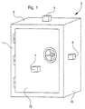
- Figure 1 shows an enclosure 1 of a safe 3 equipped with three detectors 5 to 7 connected to a alarm system (not shown). Detectors 5 and 6 are placed respectively on walls 9 and 10 of enclosure 1, and detector 7 is placed on a door access 12 to the safe 3. Such detectors are arranged to be able to measure a parameter related to the enclosure, for example a vibration or an elevation of temperature, and to be able to send a signal in response can trigger, via the alarm system, the supply an alarm signal, for example a telephone call.
- a parameter related to the enclosure for example a vibration or an elevation of temperature
- detectors 5 to 7 are arranged to detect a vibration propagating on one of the walls 9 or 10, and on the door 12. Let’s consider also the case where door 12 is the subject of a attempted break-in, and that this attempt causes propagation of a vibration on this door.
- the equipment described in connection with FIG. 1 then makes it possible to remotely report the existence of an abnormal situation in the environment of the enclosure.
- Document FR 2,694,650 describes a system comprising a sensor capable of detecting waves from air mass movements due to the opening of a door or a window in an enclosed space. This system can receive the signal from the sensor, compare this signal to memorized signals and, in the event of recognition of these signals, provide an alarm control signal corresponding to the opening of the door or window.
- Document DE-A-44 38 168 describes a lock of a access door, comprising: a mechanism capable of controlling locking and / or unlocking the door access; specific sensors or transducers to detect a hole through the lock, or an opening in the access door; and an alarm system comprising a unit which may, in response to detection of one sensors, activate an alarm siren.
- detectors work is independent of phenomena occurring in the environment of the enclosure, such as a rise in temperature linked to an expected seasonal climatic phenomenon.
- Another disadvantage of the detector in Figure 1 is that it should be placed on one of the walls of the enclosure, making the detector visible from outside, so that it can be subject to fraudulent manipulation.
- the second type of protective devices is commonly called "informer".
- FIG. 2A represents a rear front view of a access door 18 allowing access to a safe such than that shown in Figure 1, a panel of this door having been removed to allow the structure to be seen internal of such a door.
- the door 18 is conventionally fitted with locks 20, a linkage 22 and an informer 24, the operation will be explained below.
- the informer 24 includes a mechanism 26 capable of immobilizing the linkage 22, this mechanism being independent of the lock 20.
- the informer 24 further comprises a device of arming 28 suitable for maintaining this mechanism in a so-called retaining position.
- the mechanism 26 consists of two locks 29 which are arranged to be able to immobilize the linkage 22, so that when you want to train then the linkage 22 for unlocking the access door, this unlocking is no longer allowed, like a blockage caused by the bolt of the lock from this door.
- the arming device 28 can be consisting of a glass plate connected to latches and preloaded springs, these components being arranged so that the informer is kept in a pre-stressed position, or retaining position.
- the existing informers are essentially thermal informers capable of triggering following a anomalous evolution of the ambient temperature of the environment in which these informers are arranged. he there are also shock informers suitable for trigger following a shock applied to the protected wall by such a informer.
- Figure 2B illustrates the operation of the informer 24, in the event that door 18 is the subject of an attempt burglary.
- this attempt breaking has the effect of releasing the device armament 28 relative to its retaining position, and activate the informer 24.
- the various components, and including locks 29, which were originally prestressed are moved to a position where they immobilize the linkage 22. Consequently, the door 18 remains in the locked position, preventing any no one to open the safe. In other words, the attempted break-in is made unsuccessful.
- the document EP 0.686.744 describes a system of lock to prevent a door from opening enclosed space where the atmosphere can be harmful to humans.
- this system can detect the concentration of oxygen in the confined space, and provide a signal proportional to this concentration. If the latter is included in a predetermined range, the system can control the locking the access door.
- the third type of known protective device has intended to neutralize an aggressor, when he attempts a break-in on the enclosure.
- a device may release toxic gas, electric shock or jet of flames. In general, the installation of such devices is legally prohibited.
- the Applicant of the present invention has observed that many of the security enclosure protection only provide late reporting of a break-in including the enclosure is the object, that is to say after the break-in was successful, often after several hours of work on the enclosure.
- the break-in can be: an explosion of the enclosure continued to the massive injection of an explosive gas into the environment of the enclosure; or a tearing of the enclosure following a repetitive hammering.
- An object of the present invention is to provide a lock overcoming the aforementioned drawbacks and, more specifically, an enclosure access door lock security, this lock can manage the evolution of a parameter derived from a phenomenon occurring in the environment of the enclosure.
- Another object of the present invention is to provide a lock that can determine the nature of the phenomenon to the origin of an abnormal evolution of the detected parameter and, in response to this determination, order the locking or unlocking the access door.
- Another object of the present invention is to provide a lock that can adapt to changing parameters linked to the surrounding environment, so as to avoid locking or unlocking the access door, following an abnormal evolution of the parameter, caused by normal activity in the environment of the enclosure.
- Another object of the present invention is to provide a lock that meets the usual concerns of rationality and cost.
- the subject of the invention is an access door lock a security enclosure arranged in an environment.
- This lock includes a mechanism that can control, in response to a setpoint, locking and / or unlocking of said door, storage means may contain reference data relating to a parameter linked to this environment, in particular thresholds predetermined depending on said environment, and / or the material arrangement of said enclosure, and / or daily activity in said environment.
- This lock further includes a processing unit capable of receive measurement data of said parameter provided by a transducer, as well as said data of reference, determine if it is normal for the phenomenon to the origin of an anomalous evolution of said parameter had place and, depending on the result of this determination, providing said control instruction to said mechanism.
- the lock can provide the locking control on its own and / or unlocking, from the measured values of the parameter, which achieves centralized management of this control, and gives the lock management autonomy of the evolution of the parameter.
- the lock according to the present invention corresponds to a new type of protection device against attempts break-in on the enclosure, making it possible to detect a anomalous evolution of a parameter linked to the environment, to analyze this evolution, and to order in response the locking and / or unlocking the access door.
- the access door when locked by the lock does not requires no destructive intervention to be able to new access to the enclosure, unlike classical informers described above in relation to Figures 2A and 2B.
- the access door can be unlocked by a locker provided by a code specific, this instruction being provided from the exterior, for example through a connection to a portable processing unit.
- Another advantage of such an arrangement is that the lock may cause locking and / or unlocking the access door without using an additional connection to the linkage of this door.
- An advantage of being able to contain such data reference is to allow a programmer to adapt the lock to the environment of the enclosure, so as to avoid unnecessary unlocking or locking of the access door, following an anomalous evolution of the parameter measured, caused by normal activity in the environment of the enclosure or by a phenomenon local climate change.
- Such lock can advantageously provide an order as preventive, from the detection of the first steps of a anomalous evolution of the parameter.
- the unity of treatment of the lock according to the present invention is arranged to produce, among a plurality of signatures, an identification of the signature which corresponds to data relating to the measurement of the parameter, which advantage of determining the nature of a phenomenon to the origin of an anomalous evolution of the parameter, before decide whether the access door should be locked or unlocked. This allows in particular to avoid a door lock accidentally released of access, for example under the influence of a harmless shock, without that no attempted break-in has actually taken place location.
- the means of memorizing the lock according to the present invention may receive and contain data relating to the measurement of the parameter, so as to update a log events retracing the history of the lock, which has the advantage of providing monitoring of the measured values of the parameter, i.e. to allow a posteriori a analysis of events in the history of the lock, especially those relating to possible break-ins.
- Another advantage linked to the arrangement of such means of memorization is to guarantee the survival of the data contained in the event log, since this the latter is contained in the lock itself.
- the lock according to the present invention incorporates the transducer, which has for the advantage of strengthening the autonomy of the lock.
- the latter thus includes a restricted number components which, arranged in a monolithic manner, perform the locking and locking functions unlocking of the access door, as well as that of management of the evolution of the parameter, which responds to usual concerns of rationality and cost.
- Another advantage linked to the incorporation of transducer in the lock is to guarantee discretion and the camouflage of the protection device produced by the lock, especially the fact that the transducer is not more visible outside the enclosure.
- the lock according to the present invention may include an interface for communication linked to the processing unit, which has the advantage of allowing an outside user to the enclosure to remotely monitor this enclosure, without that it is necessary to place a video camera proximity to the enclosure, this camera being difficult to install and expensive.
- the user can have remote knowledge of an anomalous evolution of the parameter measured and, thus, predict the future evolution of this parameter, in order to determine if this evolution derives an involuntary phenomenon (for example a seasonal temperature increase) or voluntary (e.g. attempted break-in brought on the enclosure).
- the lock according to the present invention can provide signaling to the user at the start of an attempt break-in on the enclosure, which also allows avoid inadvertent locking or unlocking from the access door.
- Another advantage linked to the arrangement of such communication interface is to remotely get a followed by the measured values of the parameter, these values can be recorded in an event log which is offset from the enclosure.
- This newspaper can thus constitute a memory of the lock, which can be analyzed a posteriori to identify the author (s) of an attempted break-in.
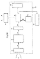
- FIG. 3A represents a diagram in the form of blocks of a first embodiment of a lock according to the present invention, designated by the reference 31.
- the lock 31 is intended to equip an access door a safety enclosure (not shown in FIG. 3A) arranged in an environment.
- This lock includes a mechanism 33 which can control, in response to a setpoint control, locking and / or unlocking said access door.
- a mechanism 33 which can control, in response to a setpoint control, locking and / or unlocking said access door.
- the command setpoint can thus order the locking or release of the linkage from the access door.
- the lock 31 further comprises a unit of processing 37 connected to mechanism 33 and capable of managing a change of state of lock 31 (i.e. a locking or unlocking the access door), and guarantee the current state.
- a processing unit 37 the component sold under the name "H83834" by the company "Hitachi", this component being arranged and programmed as described in more detail below.
- the processing unit 37 is connected to a transducer 35 arranged to provide measurement values X0 of a parameter X linked to the environment of the enclosure, this parameter being able to evolve following a phenomenon producing in the enclosure environment.
- the parameter X in the current case of an enclosure provided with metal walls, the parameter X can be the ambient temperature outside or at inside the enclosure, this temperature can be thermally conducted by these walls.
- the transducer 35 used in lock 31 includes a ohmic resistance varying according to the temperature, such resistance being known to those skilled in the art. In the preferred case where the access door is equipped with a electronic lock, said resistance is arranged on the electronic circuit which supports this lock.
- the parameter X can be a vibration likely to propagate on a wall of the enclosure.
- the transducer 35 comprises a accelerometer such as that marketed under the reference “ADXLOS" by the company “Analog Device”.
- ADXLOS the reference
- said accelerometer is fitted on the electronic circuit which supports this lock.
- the parameter X can be the presence of a foreign body enjoying a physiological activity emitting signals having a wavelength belonging to the infrared domain.
- the transducer 35 comprises a detector of presence known per se, arranged so as to be able detect, for example, the presence of a locked up person in the enclosure, and provide in response a logic signal to the processing unit 37, the latter being able to warn of such presence a user outside of the enclosure.
- the unit of processing 37 is arranged to receive data relating to the measurement of parameter X, in particular the measured values X0 supplied by the transducer 35.
- the lock 31 further comprises means for shaping 39 connected to the transducer 35, and a analog-digital converter 41 connected to the means 39 and the processing unit 37.
- the shaping means 39 are arranged in such a way so that they can receive from transducer 35 them measured values X0, and provide first data designated X1 from the measurement of parameter X, as this is described below.
- the means of placing shaped 39 include bandpass filters programmable known per se.
- the analog-digital converter 41 is arranged so that it can receive in analog form X1 data, convert that data to digital form in second data designated X2, and provide to the processing unit 37 the data X2.
- analog-to-digital converter 41 we used as analog-to-digital converter 41 the analog-to-digital converter integrated in the component "H83834" already described above.
- measured values X0 can be processed by the processing unit 37.
- the lock 31 includes storage means 43 which can contain third data or relative reference data at parameter X, this data being preprogrammed during installation of the speaker in an environment specific.
- the reference X3 will designate this reference data.
- these data constitute thresholds predetermined depending on the environment and / or the physical arrangement of the enclosure, and / or activity daily in the environment.
- the predetermined thresholds may include minimum and / or maximum values of parameter X, and / or minimum and / or maximum values of its variation over a predetermined period.
- ily activity corresponds to a succession of first time slots during which the access door can be unlocked or locked, by providing the lock 31 with access codes, and second schedules during which the door access cannot be unlocked.
- the storage means 43 are connected to the processing unit 37, so that this unit can access X3 data.
- storage means 43 the EEPROM memory marketed under the name "X24325S” by the company "XICOR".
- the processing unit 37 can be arranged to compare the predetermined thresholds with the X2 data, way to determine if an abnormal evolution of the parameter X is within the range delimited by said value minimum and / or said maximum value. According to the result of this comparison, the processing unit 37 can provide mechanism 33 with the locking instruction or unlocking. In other words, the processing unit 37 checks whether the measured values X0, after setting form and conversion, are within a range in which the values of parameter X, or those of its variations, are considered normal, i.e. occurring during normal activity in the environment of the enclosure.
- Lock 31 is particularly suitable for management of the air temperature present in the environment of the enclosure, as illustrated by in more detail below.
- the lock 31 incorporates, preferably all the components connected to the treatment 37. This incorporation is illustrated in figure 3A and following, by a line shown in dotted lines. However, as an alternative embodiment, it goes from so that the transducer 35 can be arranged close to the lock according to the present invention, without being there incorporated.
- FIG. 3B represents a diagram in the form of blocks of a second embodiment of a lock according to the present invention, designated by the reference 44. It will be noted that objects represented in FIG. 3B and designated by the same references as objects represented in FIG. 3A are substantially identical to those described in relation to FIG. 3A.
- the storage means 43 of the lock 44 contain fourth data designated X4 comprising a plurality of predetermined data or signatures, each signature corresponding to data representing the effect on the parameter X of a phenomenon known.
- this condition may be voluntary in nature (e.g. piercing of the access door, or a change in the bolt position lock following picking of this lock) or involuntary (for example an industrial activity producing near the enclosure, or activity atmospheric temperature change).
- Signatures can be stored for this purpose during the installation of lock 44, like the data X3.
- these signatures can understand the vibrations specific to the operation of a air conditioning, or the use of a jackhammer near the enclosure.
- the storage means 43 may contain as signatures the X2 data from the measurement of parameter X.
- the processing unit 37 of the lock 44 is also arranged so that it can achieve, among the signatures contained in the means of memorization 43, an identification of the signature which is substantially equal to the X2 data from the transducer 35.
- the processing unit 37 checks whether the variation over a predetermined period of time measured parameter X, after formatting and conversion, is substantially equal to one of the signatures known by the lock 44.
- the processing unit 37 supplies the mechanism 33 an instruction likely to command a locking and / or unlocking the access door. In other words, the processing unit 37 can thus determine if an abnormal evolution of the measured parameter X is related to a known phenomenon, i.e. if it is normal that this phenomenon took place.
- Lock 44 is particularly suitable for management of the vibration likely to spread on the enclosure walls, as shown so more detailed below.
- the lock 31, as well as the lock 44 may include a communication interface 45 connected to the processing unit 37, this interface comprising data display means allowing, where appropriate, display of the lockout setpoint or release provided to mechanism 33, and / or display X0 measurement data.
- Communication interface 45 may also include means for introducing data, so the processing unit 37 can establish one-way communication or bidirectional with a user outside the environment of the enclosure. So the unity of processing 37 can transfer to this user the measured values of parameter X and, where applicable, the locking and / or locking instruction supplied to mechanism 33.
- the external user can remotely interrogate the processing unit 37 to provide a new lockout or unlocking to validate or invalidate the one provided in response to measured values X0. He can also modify the X3 data contained in the means of memorization 43.
- This improved embodiment of the lock 31, as well as lock 44, is particularly suitable for managing the presence of a person in the enclosure. Indeed, consider the case where the enclosure is provided a conventional presence detector. Suppose then, after locking the access door, a person is locked in the enclosure. The arrangement described above allows in this case to detect the presence of this person, and allows to provide in response the display of a message to the external user, via the interface communication 45. In this case, this user can remotely decide to unlock (or lock) the access door, to allow (or not allow) the release of the person locked in the enclosure.
- the lock 31, as well as the lock 44 may further comprise means 47 for provide alarm signals.
- these means are arranged so that they provide alarm signals, when they receive alarm control signals.
- these means consist of at least one bistable relay known per se, to which is connected, by example, a telephone transmitter or a transmitter sound.
- the supply means 47 are connected to the processing unit 37, so that this unit can provide alarm control signals, depending results from said comparison and / or said identification of the data coming from the transducer 35, this comparison and this identification being carried out by the processing unit 37.
- a programmer can enter a range of temperature or a range of temperature gradient, in the storage means 43, via the interface of communication 45 and the processing unit 37.
- a range is defined by said minimum value and / or said maximum value so that when an evolution of the ambient temperature corresponds to values included in this range, this evolution is considered to be normal.
- FIG. 4A represents a curve Experimental 51 illustrating the evolution of temperature T during the designated time t, the temperature T being the ambient temperature linked to the environment of the enclosure.
- the transducer 35 continuously supplies a value of the temperature T at processing unit 37 which analyzes periodically the values supplied by the transducer 35.
- the temperature T thus measured is worth T1 then, at an instant t2, it is worth T2, the interval of time between instants t1 and t2 corresponding to a predetermined measurement period ⁇ t.
- the reference Tmax designates the maximum temperature value T, above which it is considered to reflect an abnormal situation.
- the temperature T measured at time t1 is less than the value Tmax, while the temperature T measured at time t2 is greater than this value. Consequently, the processing unit 37 can order the alarm means 47 to supply alarm signals, to signal to a data subject the existence of an abnormal situation in the environment of the enclosure, linked to an abnormal rise in its temperature room.
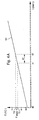
- FIG. 4B represents an experimental curve 55 illustrating the evolution of the temperature T during the designated time t. So in this example, at an instant t3, the temperature T thus measured is worth T3 then, at an instant t4, it is worth T4, the interval of time between instants t3 and t4 corresponding to a predetermined measurement period ⁇ t.
- the reference ⁇ T designates the temperature difference between two measurements consecutive.
- the processing unit 37 determines the temperature gradient between times t3 and t4, that is to say the ratio ⁇ T / ⁇ t.
- Figure 4B illustrates the case where the temperature gradient is included in said beach, this situation being represented during the period delimited by the initial instant- t0 and an instant t5 (see arrow A). Now suppose that said gradient is located outside of said range. This situation is illustrated in FIG. 4B and, more particularly, in the period starting at time t5 (see arrow B). In Consequently, the processing unit 37 controls the means alarm 47 the supply of alarm signals, for report to a data subject the existence of a abnormal situation in the environment of the enclosure, linked to an abnormal rise in the temperature gradient ambient T.
- a programmer can introduce signatures in the storage means 43, via the communication interface 45 and the processing unit 37.
- Figure 5A represents a curve 61 illustrating the evolution of the first vibration X0 measured over time t.
- the transducer 35 provides a sample of the time course of the first vibration X0.
- the sample in FIG. 5A corresponds to a time window of 100 ms.
- the processing unit 37 determines the spectral image of this sample.
- FIG. 5B represents a curve 63 illustrating a spectral image of the sample represented in FIG. 5A. Then the processing unit 37 analyzes this image to extract three main frequencies corresponding to the three maximum amplitudes of said spectral image.
- the references A1 to A3 denote the three main amplitudes, and the references F1 to F3 denote the three corresponding frequencies.
- Table 1 represents the three main amplitudes Ai and the associated frequencies Fi, resulting from experimental results carried out by the Applicant of the present invention, in relation to FIGS. 5A and 5B.
- i 1 2 3 Have 1.00 0.68 0.38 Fi (Hz) 51 680 650
- the processing unit 37 checks whether the three couples (Fi, Ai) do not correspond to one known signature (i.e. to couples previously introduced by the programmer, during the installation of the system, or in past experiences).
- the unit of processing 37 does not control the supply of signals alarm.
- the unit of processing 37 orders in response the supply of alarm signals, via the supply means 47.
- the programmer or a authorized user must provide a response in response at lock 44.
- This instruction validates if the processing unit 37 must consider said evolution as the effect of a normal or abnormal situation, in introducing as a signature in the means of memorization 43 the three couples (Fi, Ai).
- lock 44 is thus provided with a memory or learning function allowing to acquire data coming under its experience, within a specific environment in which this lock is arranged. This gives it advantageously the faculty of an interpretation "intelligent" events that disturb it in the part of his daily exercise.
- the Applicant of the present invention experimentally produced a second vibration X0 using the same vibrating drill as that used in connection with FIGS. 5A and SE, but applied to a different location.
- the references used to describe the first vibration X0 will also be used for describe the second vibration X0.
- FIGS. 5C and 5D represent the experimental results linked to the second vibration X0, and table 2 represents the three main amplitudes Ai and the associated frequencies Fi, linked to the second vibration X0.
- i 1 2 3 Have 1.00 0.67 0.35 Fi (Hz) 52 680 650
- the time sample of the second vibration X0 has a waveform 65 different from that of the sample represented in FIG. 5A (i.e. the curve 61).
- the spectral image of the second vibration X0 has a form wave 66 identical to that shown in Figure 5B.
- the first and second vibrations X0 made by the Applicant of the present invention provide two different time samples (shown in Figures 5A and 5C, respectively) which have two identical spectral images (shown in figures 5B and 5D, respectively).
- the first and second vibration X0 come from the same phenomenon (the application of an electric drill on a wall of the enclosure), this phenomenon being associated with a signature specific corresponding to the spectral images of the figures 5B and 5D.
- the Applicant of the present invention has experimentally performed a third vibration X0 at using a grinder applied to said wall.
- a grinder applied to said wall Through for the sake of simplicity, the references used to describe the first and second vibrations X0 will be used also to describe the third vibration X0.
- Figures 5E and 5F show the results experimental linked to the third vibration X0.
- the time sample of the third vibration X0 has a waveform 69 which is significantly different from that of the samples shown in Figures 5A and 5C (i.e. curves 61 and 65 respectively).
- the third vibration X0 has a spectral image which has a substantially 70 waveform different from that shown in Figure 5B (i.e. curve 63).
- the third vibration X0 is associated with a signature different from that associated at the first and second vibrations X0, which confirms the existence of a signature specific to the grinder, and a signature specific to the electric drill. Therefore, the processing unit 37 orders in response the supply alarm signals, via the supply means 47.
- a lock can be provided according to the present invention capable of managing the evolution of a sound signal neighboring the enclosure, or that of the fraction molar of a gas present in the environment of this pregnant.
- a lock can be provided according to the present invention capable of managing changes in several parameters related to the environment of the enclosure equipped with a lock according to the present invention, by connecting to said unit of processing this lock of the appropriate transducers in parallel.
Landscapes
- Physics & Mathematics (AREA)
- General Physics & Mathematics (AREA)
- Engineering & Computer Science (AREA)
- Computer Security & Cryptography (AREA)
- Lock And Its Accessories (AREA)
Claims (17)
- Schloss (31; 44), das für die Verwendung an einer Zugangstür eines Sicherheitsbehälters, der in einer Umgebung angeordnet ist, vorgesehen ist und umfasst:wobei dieses Schloss dadurch gekennzeichnet ist, dass es außerdem Speichermittel (43) umfasst, die Referenzdaten (X3; X4) für den Parameter enthalten können, wobei diese Daten von der Umgebung und/oder von der materiellen Anordnung des Behälters und/oder von der täglichen Aktivität in der Umgebung abhängen, und dass die Verarbeitungseinheit so beschaffen ist, dass sie: Zugang zu den Referenzdaten hat; die Messdaten in der Weise verarbeitet, dass sie die verarbeiteten Messdaten (X2) mit den Referenzdaten vergleicht, um festzustellen, ob es normal ist, dass eine Entwicklung des Parameters während einer vorgegebenen Zeitspanne erfolgt, und/oder ob es normal ist, dass das Phänomen am Ausgangspunkt dieser Entwicklung stattfindet; und in Reaktion darauf einen Stellwert liefert, der dem Mechanismus die Verriegelung und/oder die Entriegelung der Zugangstür befehlen kann.einen Mechanismus (33), der die Verriegelung und/oder die Entriegelung der Zugangstür steuern kann;einen Wandler (35), der Messdaten (X0) liefern kann, die einen mit der Umgebung in Beziehung stehenden Parameter (X) repräsentieren; undeine Verarbeitungseinheit (37), die die Messdaten (X0) empfangen kann,
- Schloss (31) nach Anspruch 1, dadurch gekennzeichnet, dass die Referenzdaten einen oder mehrere vorgegebene Schwellenwerte (X3) bilden, die einen Minimalwert und/oder einen Maximalwert des Parameters (X) und/oder einen Minimalwert und/oder einen Maximalwert der Änderung des Parameters im Verlauf der vorgegebenen Zeitspanne enthalten.
- Schloss (31) nach Anspruch 2, dadurch gekennzeichnet, dass die Verarbeitungseinheit (37) so beschaffen ist, dass sie:Zugang zu dem oder den vorgegebenen Schwellenwerten (X3) hat;die Messdaten (X0) in der Weise verarbeitet, dass sie die verarbeiteten Messdaten (X2) mit dem oder den vorgegeben Schwellenwerten (X3) vergleichen kann;feststellt, ob diese verarbeitenden Messdaten (X2) in dem durch die vorgegebenen Schwellenwerte begrenzten Bereich liegen, d. h. ob die Entwicklung des Parameters in diesem Bereich enthalten ist; undin Abhängigkeit vom Ergebnis dieser Bestimmung den Stellwert liefert.
- Schloss (44) nach Anspruch 1, dadurch gekennzeichnet, dass die Speichermittel (43) außerdem mehrere Signaturen enthalten, wovon jede vierten vorgegebenen Daten (X4) entspricht, die die Wirkung auf den Parameter (X) eines vorgegebenen Phänomens repräsentieren, das in der Umgebung auftritt.
- Schloss (44) nach Anspruch 1, dadurch gekennzeichnet, dass die Speichermittel (43) außerdem die verarbeiteten Messdaten (X2) enthalten, wobei diese letzteren als Signatur verwendet werden können.
- Schloss (44) nach Anspruch 4 oder 5, dadurch gekennzeichnet, dass die Verarbeitungseinheit (37) so beschaffen ist, dass sie:Zugang zu den Signaturen hat;die Messdaten (X0) in der Weise verarbeitet, dass sie die verarbeiteten Messdaten (X2) mit diesen Signaturen vergleichen kann;feststellt, ob die verarbeiteten Messdaten (X2) im Wesentlichen gleich einer der Signaturen sind, d. h. ob die Entwicklung des Parameters mit einem bekannten Phänomen in Beziehung steht; undin Abhängigkeit vom Ergebnis dieser Bestimmung den Stellwert liefert.
- Schloss (31; 44) nach Anspruch 1, dadurch gekennzeichnet, dass die Speichermittel (43) Daten, die von der Verarbeitungseinheit (37) stammen, insbesondere die Messdaten (X0) und/oder die verarbeiteten Messdaten (X2), empfangen können, um ein Ereignisjournal, das die Historie des Schlosses angibt, zu aktualisieren.
- Schloss (31; 44) nach Anspruch 1, dadurch gekennzeichnet, dass es den Mechanismus (33), die Verarbeitungseinheit (37), den Wandler (35) und die Speichermittel (43) enthält.
- Schloss (31; 44) nach Anspruch 1, dadurch gekennzeichnet, dass es außerdem eine Kommunikationsschnittstelle (45) umfasst, die mit der Verarbeitungseinheit (37) verbunden ist, wobei diese Schnittstelle Mittel zum Anzeigen von Daten enthält, die die Anzeige des an den Mechanismus gelieferten Stellwerts und/oder die Anzeige der Messdaten (X0) ermöglichen.
- Schloss (31; 44) nach Anspruch 9, dadurch gekennzeichnet, dass die Kommunikationsschnittstelle (45) außerdem Dateneingabemittel umfasst, derart, dass ein Anwender außerhalb der Umgebung in der Lage ist: einen neuen Stellwert zu liefern, um diese Lieferung in Reaktion auf die Messdaten (X0) für gültig oder ungültig zu erklären; und/oder von der Verarbeitungseinheit (37) Daten bezüglich des Zustandes eines zusätzlichen Parameters zu empfangen.
- Schloss (31; 44) nach Anspruch 3 oder 7, dadurch gekennzeichnet, dass es außerdem mit der Verarbeitungseinheit (37) verbundene Mittel (47) für die Lieferung von Alarmsignalen umfasst, derart, dass diese Einheit in Abhängigkeit vom Ergebnis der Bestimmung Alarmsteuersignale liefern kann.
- Schloss (31; 44) nach Anspruch 1, dadurch gekennzeichnet, dass der Parameter (X) die Umgebungstemperatur der Umgebung des Behälters ist.
- Schloss (31; 44) nach Anspruch 1, dadurch gekennzeichnet, dass der Parameter (X) eine Vibration ist, die sich längs der Wand des Behälters ausbreitet.
- Schloss (31; 44) nach Anspruch 1, dadurch gekennzeichnet, dass der Parameter (X) der molare Anteil eines Gases ist, das in der Umgebung des Behälters vorhanden ist.
- Schloss (31; 44) nach Anspruch 1, dadurch gekennzeichnet, dass der Parameter (X) ein Schallsignal ist, das in der Umgebung des Behälters vorhanden ist.
- Schloss (31; 44) nach Anspruch 1, dadurch gekennzeichnet, dass der Parameter (X) ein Signal ist, das der Gegenwart eines fremden Organismus eigentümlich ist, der eine physiologische Aktivität hat, die ein solches Signal aussenden kann.
- Sicherheitsbehälter, der mit einem Schloss (31; 44) nach einem der Ansprüche 1 bis 16 ausgerüstet ist.
Priority Applications (1)
| Application Number | Priority Date | Filing Date | Title |
|---|---|---|---|
| EP98954325A EP1023512B1 (de) | 1997-10-14 | 1998-10-02 | Schloss zur kontrolle des zeitlichen verlaufs eines an die umgebung gebundenen parameters |
Applications Claiming Priority (4)
| Application Number | Priority Date | Filing Date | Title |
|---|---|---|---|
| EP97117767 | 1997-10-14 | ||
| EP97117767 | 1997-10-14 | ||
| PCT/EP1998/006287 WO1999019586A1 (fr) | 1997-10-14 | 1998-10-02 | Serrure gerant l'evolution d'un parametre lie a l'environnement |
| EP98954325A EP1023512B1 (de) | 1997-10-14 | 1998-10-02 | Schloss zur kontrolle des zeitlichen verlaufs eines an die umgebung gebundenen parameters |
Publications (2)
| Publication Number | Publication Date |
|---|---|
| EP1023512A1 EP1023512A1 (de) | 2000-08-02 |
| EP1023512B1 true EP1023512B1 (de) | 2004-12-08 |
Family
ID=8227480
Family Applications (1)
| Application Number | Title | Priority Date | Filing Date |
|---|---|---|---|
| EP98954325A Expired - Lifetime EP1023512B1 (de) | 1997-10-14 | 1998-10-02 | Schloss zur kontrolle des zeitlichen verlaufs eines an die umgebung gebundenen parameters |
Country Status (6)
| Country | Link |
|---|---|
| US (1) | US6130611A (de) |
| EP (1) | EP1023512B1 (de) |
| CA (1) | CA2306431C (de) |
| DE (1) | DE69828077T2 (de) |
| ES (1) | ES2235376T3 (de) |
| WO (1) | WO1999019586A1 (de) |
Families Citing this family (14)
| Publication number | Priority date | Publication date | Assignee | Title |
|---|---|---|---|---|
| US6581986B2 (en) * | 2000-11-21 | 2003-06-24 | Tri Teq Lock And Security, L.L.C. | Bayonet locking system and method for vending machines and the like |
| US9523215B2 (en) | 2000-11-21 | 2016-12-20 | Triteq Lock And Security, Llc | Electronic locking systems for vending machines and the like |
| TW510998B (en) * | 2001-05-08 | 2002-11-21 | Mitac Int Corp | On-site production management and storage system |
| US6724303B2 (en) * | 2001-10-18 | 2004-04-20 | Corporate Safe Specialists, Inc. | Method and apparatus for monitoring a safe |
| DE10208451A1 (de) * | 2002-02-27 | 2003-09-04 | Bremicker Soehne Kg A | Fenster-/Türschloss |
| US8876172B2 (en) * | 2004-03-05 | 2014-11-04 | Triteq Lock And Security, Llc | Vending machine lock with motor controlled slide-bar and hook mechanism and electronic access |
| DE202004011462U1 (de) * | 2004-07-14 | 2004-09-23 | IKON GmbH Präzisionstechnik | Schließzylinder mit Alarmeinrichtung |
| DE102008047194A1 (de) * | 2008-09-15 | 2010-04-15 | ABUS August Bremicker Söhne KG | Verriegelungseinheit für Fenster- oder Türflügel |
| US20120262307A1 (en) * | 2011-04-17 | 2012-10-18 | Tai Cheung Poon | Systems and methods for monitoring cargo conditions |
| US11002039B2 (en) | 2012-04-20 | 2021-05-11 | Triteq Lock And Security, L.L.C. | Electronic controlled handles |
| US9950590B2 (en) * | 2012-06-25 | 2018-04-24 | Rsc Industries Inc. | Cooling system and methods for cooling interior volumes of cargo trailers |
| US9305443B2 (en) * | 2013-04-10 | 2016-04-05 | Royne Industries, LLC | LED security sensor |
| EP2997209B1 (de) | 2013-05-15 | 2021-02-17 | TriTeq Lock and Security LLC | Schloss |
| US12359465B2 (en) | 2021-02-16 | 2025-07-15 | Triteq Lock And Security, Llc | Lock |
Family Cites Families (8)
| Publication number | Priority date | Publication date | Assignee | Title |
|---|---|---|---|---|
| FR2549519B3 (fr) * | 1983-07-21 | 1985-12-06 | Int Home Systems | Coffre-fort a penes motorises et logique de commande |
| FR2694650A1 (fr) * | 1992-08-04 | 1994-02-11 | Frizet Christian | Analyseur paramétrique en temps réel de choc et d'ouverture. |
| DE4438168A1 (de) * | 1993-10-30 | 1995-05-04 | Aeg Sensorsysteme Gmbh | Schließeinrichtung mit einem Schloß und Beschlägen für Haus- und Wohnungstüren |
| US5479151A (en) * | 1994-03-31 | 1995-12-26 | Harrow Products, Inc. | Electromagnetic door lock with on-board programmable access control |
| US5479341A (en) * | 1994-04-21 | 1995-12-26 | Pihl; Lawrence E. | Electronic data security apparatus |
| US5507539A (en) * | 1994-06-06 | 1996-04-16 | Carrier Corporation | Safety device for an enclosure door |
| US5670940A (en) * | 1996-04-19 | 1997-09-23 | Trioving A.S | Electronic lock system with occupancy block |
| KR100222204B1 (ko) * | 1997-03-31 | 1999-10-01 | 구자홍 | 금고용 록킹 장치 |
-
1998
- 1998-10-02 DE DE69828077T patent/DE69828077T2/de not_active Expired - Lifetime
- 1998-10-02 EP EP98954325A patent/EP1023512B1/de not_active Expired - Lifetime
- 1998-10-02 WO PCT/EP1998/006287 patent/WO1999019586A1/fr not_active Ceased
- 1998-10-02 CA CA002306431A patent/CA2306431C/fr not_active Expired - Fee Related
- 1998-10-02 ES ES98954325T patent/ES2235376T3/es not_active Expired - Lifetime
- 1998-10-14 US US09/172,014 patent/US6130611A/en not_active Expired - Fee Related
Also Published As
| Publication number | Publication date |
|---|---|
| DE69828077T2 (de) | 2006-03-02 |
| ES2235376T3 (es) | 2005-07-01 |
| DE69828077D1 (de) | 2005-01-13 |
| WO1999019586A8 (fr) | 1999-07-01 |
| CA2306431A1 (fr) | 1999-04-22 |
| WO1999019586A1 (fr) | 1999-04-22 |
| US6130611A (en) | 2000-10-10 |
| EP1023512A1 (de) | 2000-08-02 |
| CA2306431C (fr) | 2007-04-24 |
Similar Documents
| Publication | Publication Date | Title |
|---|---|---|
| EP1023512B1 (de) | Schloss zur kontrolle des zeitlichen verlaufs eines an die umgebung gebundenen parameters | |
| EP1593099B1 (de) | Aufbewahrungsvorrichtung und verfahren für das einlegen und ausgeben eines gegenstandes in eine aufbewahrungsvorrichtung | |
| US6508397B1 (en) | Self-defense ATM | |
| EP0340078B1 (de) | Tresor, insbesondere zum Aufbewahren von Zugangsmitteln oder anderer überwachter Gebrauchsgegenstände | |
| CN110097713A (zh) | 入侵检测系统和方法 | |
| US8474690B1 (en) | Alarm and indicating system for preventing burglary and theft | |
| EP0210889B1 (de) | Modulare Überwachungs- und Alarmzentrale grosser Sicherheit und entsprechendes Betriebsverfahren | |
| JP5121122B2 (ja) | 監視装置 | |
| EP0070224B1 (de) | Überwachungs- und Alarmverfahren und entsprechende Vorrichtung | |
| FR2570747A1 (fr) | Procede et systeme de securite pour chambres fortes | |
| EP0158577B1 (de) | Kontrolleingangsschleuse für Panzerräume | |
| CH690502A5 (fr) | Système à déclenchement programmable pour le verrouillage/ déverrouillage temporisé d'une installation de sécurité. | |
| EP1792540B1 (de) | Wandbefestigtes System für Schädlingsdetektion und Schädlingsausrottung | |
| EP1405280B2 (de) | Zentralisierte scharfeinstellung eines sicherheitssystem | |
| JP4541487B2 (ja) | 金庫警備システム | |
| JP4293881B2 (ja) | 開閉体操作装置の不正検知システム | |
| EP4407580B1 (de) | Zugangskontrollsystem | |
| FR3097246A1 (fr) | Serrure miniaturisée de sécurité comportant un verrou et utilisation dans un but de sécurité | |
| JP3742424B1 (ja) | セキュリティシステム | |
| EP3649627B1 (de) | Verfahren und vorrichtung zur detektion des eindringens | |
| FR2858448A1 (fr) | Dispositif de consigne et procede de surveillance d'un objet dans ce dispositif de consigne | |
| FR2892549A1 (fr) | Systeme d'alarme, unite centrale de systeme d'alarme et procede de protection d'une telle unite centrale | |
| JP2006146879A (ja) | セキュリティシステム | |
| FR2673747A1 (fr) | Centrale d'alarme destinee plus particulierement a la surveillance d'une pluralite d'appareillages proteges par des dispositifs de detection de manipulations non autorisees. | |
| BE1005225A3 (fr) | Nouvelle application d'un procede connu relatif a une surveillance electronique, 24/24 heures, anti-agression, a rearmement automatique, sans intervention humaine. |
Legal Events
| Date | Code | Title | Description |
|---|---|---|---|
| PUAI | Public reference made under article 153(3) epc to a published international application that has entered the european phase |
Free format text: ORIGINAL CODE: 0009012 |
|
| 17P | Request for examination filed |
Effective date: 20000515 |
|
| AK | Designated contracting states |
Kind code of ref document: A1 Designated state(s): CH DE ES FR GB IT LI |
|
| GRAP | Despatch of communication of intention to grant a patent |
Free format text: ORIGINAL CODE: EPIDOSNIGR1 |
|
| GRAS | Grant fee paid |
Free format text: ORIGINAL CODE: EPIDOSNIGR3 |
|
| GRAA | (expected) grant |
Free format text: ORIGINAL CODE: 0009210 |
|
| RAP1 | Party data changed (applicant data changed or rights of an application transferred) |
Owner name: KABA AG |
|
| AK | Designated contracting states |
Kind code of ref document: B1 Designated state(s): CH DE ES FR GB IT LI |
|
| REG | Reference to a national code |
Ref country code: GB Ref legal event code: FG4D Free format text: NOT ENGLISH |
|
| REG | Reference to a national code |
Ref country code: CH Ref legal event code: EP |
|
| REF | Corresponds to: |
Ref document number: 69828077 Country of ref document: DE Date of ref document: 20050113 Kind code of ref document: P |
|
| GBT | Gb: translation of ep patent filed (gb section 77(6)(a)/1977) |
Effective date: 20050318 |
|
| REG | Reference to a national code |
Ref country code: CH Ref legal event code: NV Representative=s name: ICB INGENIEURS CONSEILS EN BREVETS SA |
|
| REG | Reference to a national code |
Ref country code: ES Ref legal event code: FG2A Ref document number: 2235376 Country of ref document: ES Kind code of ref document: T3 |
|
| PLBE | No opposition filed within time limit |
Free format text: ORIGINAL CODE: 0009261 |
|
| STAA | Information on the status of an ep patent application or granted ep patent |
Free format text: STATUS: NO OPPOSITION FILED WITHIN TIME LIMIT |
|
| 26N | No opposition filed |
Effective date: 20050909 |
|
| PGFP | Annual fee paid to national office [announced via postgrant information from national office to epo] |
Ref country code: CH Payment date: 20080926 Year of fee payment: 11 |
|
| PGFP | Annual fee paid to national office [announced via postgrant information from national office to epo] |
Ref country code: GB Payment date: 20080926 Year of fee payment: 11 |
|
| REG | Reference to a national code |
Ref country code: CH Ref legal event code: PL |
|
| PG25 | Lapsed in a contracting state [announced via postgrant information from national office to epo] |
Ref country code: LI Free format text: LAPSE BECAUSE OF NON-PAYMENT OF DUE FEES Effective date: 20091031 Ref country code: CH Free format text: LAPSE BECAUSE OF NON-PAYMENT OF DUE FEES Effective date: 20091031 |
|
| PG25 | Lapsed in a contracting state [announced via postgrant information from national office to epo] |
Ref country code: GB Free format text: LAPSE BECAUSE OF NON-PAYMENT OF DUE FEES Effective date: 20091002 |
|
| REG | Reference to a national code |
Ref country code: FR Ref legal event code: PLFP Year of fee payment: 19 |
|
| REG | Reference to a national code |
Ref country code: FR Ref legal event code: PLFP Year of fee payment: 20 |
|
| PGFP | Annual fee paid to national office [announced via postgrant information from national office to epo] |
Ref country code: FR Payment date: 20170921 Year of fee payment: 20 Ref country code: IT Payment date: 20170921 Year of fee payment: 20 |
|
| PGFP | Annual fee paid to national office [announced via postgrant information from national office to epo] |
Ref country code: DE Payment date: 20170920 Year of fee payment: 20 |
|
| PGFP | Annual fee paid to national office [announced via postgrant information from national office to epo] |
Ref country code: ES Payment date: 20171103 Year of fee payment: 20 |
|
| REG | Reference to a national code |
Ref country code: DE Ref legal event code: R071 Ref document number: 69828077 Country of ref document: DE |
|
| REG | Reference to a national code |
Ref country code: ES Ref legal event code: FD2A Effective date: 20200213 |
|
| PG25 | Lapsed in a contracting state [announced via postgrant information from national office to epo] |
Ref country code: ES Free format text: THE PATENT HAS BEEN ANNULLED BY A DECISION OF A NATIONAL AUTHORITY Effective date: 20181003 |