EP1023984A2 - Strangpresskopf zum Extrusionsblasformen von Kunststoffbehältern - Google Patents
Strangpresskopf zum Extrusionsblasformen von Kunststoffbehältern Download PDFInfo
- Publication number
- EP1023984A2 EP1023984A2 EP99125478A EP99125478A EP1023984A2 EP 1023984 A2 EP1023984 A2 EP 1023984A2 EP 99125478 A EP99125478 A EP 99125478A EP 99125478 A EP99125478 A EP 99125478A EP 1023984 A2 EP1023984 A2 EP 1023984A2
- Authority
- EP
- European Patent Office
- Prior art keywords
- sleeve
- extrusion head
- head according
- nozzle body
- cams
- Prior art date
- Legal status (The legal status is an assumption and is not a legal conclusion. Google has not performed a legal analysis and makes no representation as to the accuracy of the status listed.)
- Granted
Links
Images


Classifications
-
- B—PERFORMING OPERATIONS; TRANSPORTING
- B29—WORKING OF PLASTICS; WORKING OF SUBSTANCES IN A PLASTIC STATE IN GENERAL
- B29C—SHAPING OR JOINING OF PLASTICS; SHAPING OF MATERIAL IN A PLASTIC STATE, NOT OTHERWISE PROVIDED FOR; AFTER-TREATMENT OF THE SHAPED PRODUCTS, e.g. REPAIRING
- B29C48/00—Extrusion moulding, i.e. expressing the moulding material through a die or nozzle which imparts the desired form; Apparatus therefor
- B29C48/25—Component parts, details or accessories; Auxiliary operations
- B29C48/30—Extrusion nozzles or dies
- B29C48/32—Extrusion nozzles or dies with annular openings, e.g. for forming tubular articles
- B29C48/325—Extrusion nozzles or dies with annular openings, e.g. for forming tubular articles being adjustable, i.e. having adjustable exit sections
-
- B—PERFORMING OPERATIONS; TRANSPORTING
- B29—WORKING OF PLASTICS; WORKING OF SUBSTANCES IN A PLASTIC STATE IN GENERAL
- B29C—SHAPING OR JOINING OF PLASTICS; SHAPING OF MATERIAL IN A PLASTIC STATE, NOT OTHERWISE PROVIDED FOR; AFTER-TREATMENT OF THE SHAPED PRODUCTS, e.g. REPAIRING
- B29C48/00—Extrusion moulding, i.e. expressing the moulding material through a die or nozzle which imparts the desired form; Apparatus therefor
- B29C48/03—Extrusion moulding, i.e. expressing the moulding material through a die or nozzle which imparts the desired form; Apparatus therefor characterised by the shape of the extruded material at extrusion
- B29C48/09—Articles with cross-sections having partially or fully enclosed cavities, e.g. pipes or channels
- B29C48/10—Articles with cross-sections having partially or fully enclosed cavities, e.g. pipes or channels flexible, e.g. blown foils
Definitions
- the sleeve has one at its inlet end dimensionally stable collar with an annular circumferential Flange surface, the entire surface of the nozzle body is supported. That from the melt flow to the sleeve Axial forces are exerted over the collar in the nozzle body initiated.
- the invention has for its object an extrusion head with the characteristics described above further train that large and largely wear-free Deformations and displacements on the hose outlet side End of the sleeve are possible, in the case a start-up in the manufacture of small hose diameters the melt emerging from the nozzle exit gap on Nozzle body should be excluded.
- the devices shown in the figures become Extrusion blow molding of plastic containers that are different Can have container cross-sections used.
- a tubular preform is made a thermoplastic melt from one Extruded head extruded and in a not shown Blow mold expanded into a plastic container.
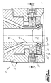
- the Extrusion head has an annular gap nozzle 1 with a mandrel 2, an annular nozzle body 3 and an elastic deformable sleeve 4.
- the sleeve 4 can in the nozzle body and / or be arranged on the mandrel 2.
- To the coat of the elastic sleeve 4 attack actuators 5 by the actuating movements of the sleeve 4 is radially deformable.
- the mandrel 2 and the sleeve 4 delimit a nozzle gap
- the Gap width due to axial adjustment movements of the mandrel 2 and / or the nozzle body 3 is changeable and its geometry by deforming the sleeve 4 during extrusion of a tubular preform can be influenced.
- the axial adjusting movements of the mandrel 2 and / or the nozzle body 3 and the radial ones exerted on the sleeve 4 Actuating movements are program-controlled.
- the sleeve 4 is only in the nozzle body 3 and / or on the mandrel 2 supported segment-shaped surfaces. 1 to 9 illustrated embodiments of the invention Sleeve 4 connected on the jacket side and in the circumferential direction spaced-apart cams 6 on the Nozzle body are supported axially. To support the sleeve 4, at least two cams 6 are required.
- the axial forces, which are exerted by the melt on the sleeve and / or arise with an elastic deformation of the sleeve, can be introduced into the nozzle body via the cams, depending on the design, the cams on the underside or both supported on the underside and on the top in the nozzle body could be.
- the distance of the cams from the lower end of the sleeve can be set as desired. It is within the scope of the invention to arrange the cams 6 at the inlet end of the sleeve 4. Preferably, the cams 6 on the jacket between the provided on the inlet-side and outlet-side end of the sleeve.
- the cam support of the nozzle body 3 is always present so arranged on the circumference of the sleeve 4 that the out of the annular gap escaping melt flow do not start on the nozzle body 3 can.
- the molded cams 6 merely stiffen the sleeve 4 on the peripheral portions of the sleeve 4.
- the sleeve portions between the cams 6 are under the effect of the sleeve 4 acting actuators deformable.
- the contact surface the cam for support in the nozzle body 3 can be independent freely designed from the connection of the cams 6 become.
- the contact surfaces 9 can be dimensioned in this way that allowable surface pressures that are low wear Sliding movement between the cams 6 and the associated Allow counter surfaces of the nozzle body or mandrel not be exceeded.
- the cams 6 in the circumferential direction a wide support surface for support on the nozzle body or mandrel and a molded onto the outer surface of the sleeve Neck 10 of smaller width.
- the width of the neck 10 and the width of the support surface 9 are independent of one another so fixable that on the one hand good support the sleeve 4 is guaranteed and on the other hand the deformability the sleeve 4 through the connection elements so little is affected as possible.
- the support takes place the sleeve 4 at four at equidistant intervals Circumferentially arranged cams 6 in the force axis the actuators 5 and across the force of the Actuators 5 are arranged.
- the cams 6 In the circumferential direction the cams 6 have a wide contact surface 9 for support on the nozzle body 3 and one on the outer surface of the Sleeve 4 molded neck 10 of smaller width on (Fig. 2).
- a mostly undesirable stiffening effect of the cams 6 on the sleeve 4 remains limited to peripheral portions are small compared to the overall circumference of the sleeve 4.
- the Circumferential sections between the cams 6 remain elastic deformable.
- the sleeve 4 on its inlet side edge opposite one End face 11 of the nozzle body is radially movable and in the Partial areas of the circumference evenly over their entire length radially adjustable.
- the cams 6 to support the Sleeve 4 and load bearing are on the underside of the nozzle retaining ring 12 which can be inserted into the nozzle body 3 radially movable on.
- the cams 6 are at the level of Positioning devices 5 arranged, the on the axis 7th arranged in the direction of force of the actuators 5 Cams 6 are connected to the actuators 5.
- the sleeve 4 has a deformable collar 13 which in the inner diameter of the retaining ring 12 with radial Game engages and forms the outer wall of the annular gap.
- the retaining ring 12 is not continuous Has ring surface but with the cams 6 of Sleeve 4 interacts in the manner of a bayonet lock.
- the sleeve 4 is in the nozzle body up to a stop can be used axially and by rotating the nozzle body 3 lockable.
- the arrangement allows assembly and disassembly the sleeve 4 from the underside of the annular gap nozzle 1. Also in the embodiments shown in FIGS. 3 and 4 the parts are similarly interchangeable.
- the retaining ring 12 with the sleeve 4 to be installed and removed as a pre-assembled assembly, the retaining ring 12, for example, by a Bayonet-type quick lock in the nozzle body 3 lockable can be.
- FIGS. 3 to 7 is the sleeve 4 at its inlet end an axial sliding seat held within the nozzle body, so that the inlet-side edge of the sleeve 4 is radial Deformation of the sleeve 4 movable in the axial direction is.
- FIGS. 3 and 4 are two cams 6 transverse to support the sleeve to the force effect of the control devices shortly before the upper one, arranged inlet end of the sleeve 4.
- the support takes place at a distance from the inlet end, e.g. B. at the level of the radial Actuators 5.
- the deformation is the Sleeve 4, particularly in the case of rectified positioning movements the actuators 5, connected with a pivoting movement.
- the cams 6 are the cams 6 on at least one surface 14 supported, which allows a tilting movement and in the embodiment adapts to the tilting movement of the cams 6.
- the contact surface 14 about an axis of rotation 15 transverse to the line of action of the actuators 5 arranged tilting.
- the cams 6 are designed as pins, the transverse to the force of the actuators 5 aligned sliding in a pin receptacle of the Nozzle body 3 are mounted and a wear sleeve 16th can wear. It is understood that the cams 6 too Can contain cone receptacles, in which surround the cones. The pin receptacle can also be arranged on a slide be movable across the axis of rotation of the pin. in the 7 is supported Cam 6 on a surface 14, according to the rules of statics is designed as a bar on two supports 17 and itself Can adjust tilting movements of the cam 6. alternative can also use disc springs to support the Cam 6 may be provided.
- the axial supports of the Sleeve 4 in the nozzle body 3 can be at any height Sleeve 4 take place.
- the nozzle body 3 can on a housing 18 of the extrusion head firmly mounted or, as indicated in Fig. 8, radial movably arranged on the housing 18 of the extrusion head his.
- a radial mobility of the nozzle body 3 can be used to center the nozzle.
- On the radially movable Nozzle bodies 3 can also have one or more Auxiliary drives 19 to be connected, which during the Hose outlet for further influencing the nozzle gap execute program-controlled movements.
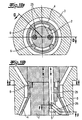
- 9a and 9b show in longitudinal section and in cross section (Section plane A-A from Fig. 9a) a further embodiment of the extrusion head according to the invention.
- the elastically deformable sleeve 4 has an axial Sliding seat arranged in the nozzle body 3 and facing the circumference two or more cams 6.
- the Actuators 5 are on a sliding seat underside plate 24 guided on the nozzle body 3rd is screwed on. Between the plate 24 and the cams 6 there remains a gap which allows the cams 6 to tilt, when the sleeve 4 is deformed radially.
- the extrusion head according to the invention is elastic deformable sleeve 4 arranged on the mandrel 2.
- 10a is a cross section in the sectional plane E-E shown in Fig. 10b.
- 10b shows a longitudinal section in the Section plane D-D from Fig. 10a.
- 10c shows sections the section F-F of Fig. 10b.
- a comparative 10a to 10c it can be seen that that the sleeve 4 at its inlet-side, upper end has internal cams 6 which are axially supported on the mandrel 2 are.
- the support can be on two or more cams 6 respectively.
- the actuating device 5 for radial deformation the sleeve has at least one adjusting rod 25, connected via a lever 26 to the inside of the sleeve is.
- two can be actuated separately Adjusting rods 25 with associated levers 26 are provided. 10c that the sleeve 4 has a wall thickness profile with thick and thin places. The intended thickenings influence the radial deformation the sleeve 4 and that when the Actuators 5 adjusting profile of the sleeve 4th
- Extrusion head is one in the nozzle body 3 elastically deformable sleeve 4 used on her has an annular collar 27 on the inlet end, which is not on its entire ring surface but only is axially supported on segment-shaped surfaces. To this Way, the effects described above can also can be achieved.
- the nozzle body 3 has an annular surface to support the sleeve 4, which for the segment-shaped Supporting the sleeve in the circumferential direction with elevations 28 and / or depressions 29 is provided.
- the one on the right Section of elevations 28 recognizable in FIG. 11 support the collar 27 of the sleeve 4 up and down.
- the support surface could also be used of the annular collar 27 with a profile Projections and / or recesses for the segment-shaped Have support of the sleeve 4. It goes without saying that the support described also used in a sleeve 4 could be arranged on the mandrel 2. Further can the radial wall thickness of the annular collar 27 in Circumferential direction may be non-uniform.
- profiling device 21 can be used as a profiling device 21 radially movable slider can be arranged in the nozzle body. All profiling device 21 described above can in a channel area above the sleeve 4 or on elsewhere in the annular gap.
- the nozzle body 3 is expediently formed in several parts and has an upper nozzle part and a ring-shaped, interchangeable Insert 23 on (Fig. 3).
- the acting on the sleeve 4 Actuators 5 are connected to the upper part of the nozzle, the connection acting on the sleeve 4 can be released by a quick coupling. After releasing the clutch the insert 23 with the sleeve and the mandrel 2 without removing the upper part of the nozzle and the adjusting devices 5 be replaced. It is also possible to derive from the Sleeve 4, the retaining ring 12 and one with the retaining ring 12 screwed ring 30 to be replaced as a complete assembly.
Landscapes
- Engineering & Computer Science (AREA)
- Mechanical Engineering (AREA)
- Manufacturing & Machinery (AREA)
- Blow-Moulding Or Thermoforming Of Plastics Or The Like (AREA)
- Extrusion Moulding Of Plastics Or The Like (AREA)
- Processing And Handling Of Plastics And Other Materials For Molding In General (AREA)
Abstract
Description
- Fig. 1
- einen Längsschnitt durch eine Ringspaltdüse eines Strangpresskopfes,
- Fig. 2
- den Schnitt A-A aus Fig. 1,
- Fig. 3
- einen Schnitt durch eine zweite Ausführung des erfindungsgemäßen Strangpresskopfes in der in Fig. 4 dargestellten Schnittebene B-B,
- Fig. 4
- den Schnitt C-C aus Fig. 3,
- Fig. 5 bis 11
- weitere Ausführungsbeispiele des erfindungsgemäßen Strangpresskopfes, teils im Längsschnitt und teils im Querschnitt.
Claims (24)
- Strangpresskopf zum Extrusionsblasformen von Kunststoffbehältern mitwobei die Hülse (4) einen Düsenspalt begrenzt, dessen Spaltbreite durch axiale Stellbewegungen des Dorns (2) und/oder des Düsenkörpers (3) veränderbar ist und dessen Geometrie durch Deformierung der Hülse (4) während der Extrusion eines schlauchförmigen Vorformlings beeinflussbar ist, dadurch gekennzeichnet, dass die Hülse (4) im Düsenkörper (3) und/oder am Dorn (2) nur an segmentförmigen Flächen axial abgestützt ist.einer Ringspaltdüse (1), die einen Dorn (2) und einen ringförmigen Düsenkörper (3) aufweist,einer elastisch deformierbaren Hülse (4)) undStelleinrichtungen (5) zur radialen Deformierung der elastischen Hülse (4),
- Strangpresskopf nach Anspruch 1, dadurch gekennzeichnet, dass die Hülse (4) mantelseitig angeschlossene und in Umfangsrichtung mit Abstand zueinander angeordnete Nocken (6) aufweist, die im Düsenkörper (3) oder am Dorn (2) axial abgestützt sind.
- Strangpresskopf nach Anspruch 2, dadurch gekennzeichnet, dass die Nocken (6) zumindest nach unten abgestützt sind.
- Strangpresskopf nach Anspruch 2 oder 3, dadurch gekennzeichnet, dass die Nocken (6) in Umfangsrichtung eine breite Auflagefläche (9) zur Abstützung und einen an die Mantelfläche der Hülse (4) angeformten Hals (10) geringerer Breite aufweisen.
- Strangpresskopf nach einem der Ansprüche 2 bis 4, dadurch gekennzeichnet, dass die Nocken (6) identisch ausgebildet und in äquidistanten Abständen auf gleicher Höhe angeordnet sind.
- Strangpresskopf nach einem der Ansprüche 1 bis 5, dadurch gekennzeichnet, dass die segmentförmigen Flächen zur Abstützung in der Kraftwirkungsachse (7) und/oder in einer Achse (8) quer zur Kraftwirkung der Stelleinrichtungen (5) angeordnet sind.
- Strangpresskopf nach Anspruch 2, dadurch gekennzeichnet, dass die am Umfang angeordneten Nocken (6) zur Erzielung einer unsymmetrischen Deformation der Hülse (4) in Umfangsrichtung unterschiedlich breit ausgebildet sind und/oder in nicht äquidistanten Abständen am Umfang angeordnet sind.
- Strangpresskopf nach einem der Ansprüche 2 bis 7, dadurch gekennzeichnet, dass die Hülse (4) in den Düsenkörper (3) bis zu einem Anschlag axial einsetzbar und durch eine Drehbewegung im Düsenkörper (3) verriegelbar ist, wobei die Nocken (6) nach Art eines Bajonettverschlusses oder einer Klauenkupplung zugeordnete Auflageflächen des Düsenkörpers (3) hinterfassen.
- Strangpresskopf nach einem der Ansprüche 2 bis 8, dadurch gekennzeichnet, dass die Nocken (6) auf einem in den Düsenkörper (3) einsetzbaren Haltering (12) aufliegen und dass die Hülse (4) einen deformierbaren Kragen (13) aufweist, der in den Innendurchmesser des Halterings (12) mit radialem Spiel eingreift.
- Strangpresskopf nach einem der Ansprüche 2 bis 9, dadurch gekennzeichnet, dass die Hülse (4) an ihrem einlaufseitigen Ende mit einem axialen Schiebesitz innerhalb des Düsenkörpers (3) gehalten ist, so dass der einlaufseitige Rand der Hülse (4) bei radialer Deformation der Hülse in axialer Richtung beweglich ist und dass die in einer Ebene unterhalb des einlaufseitigen Randes angeordneten Nocken (6) an einer Auflagefläche (14) des Düsenkörpers (3) abgestützt sind, die eine Kippbewegung der Nocken (6) zulässt.
- Strangpresskopf nach Anspruch 10, dadurch gekennzeichnet, dass die Auflagefläche (14) sich an die Kippbewegung der Nocken (6) anpasst.
- Strangpresskopf nach Anspruch 11, dadurch gekennzeichnet, dass die Auflagefläche (14) um eine Drehachse (15) quer zur Kraftwirkungslinie der Stelleinrichtungen (5) kippbeweglich angeordnet ist.
- Strangpresskopf nach Anspruch 11, dadurch gekennzeichnet, dass die Auflagefläche (14) als Balken auf zwei Stützen (17) ausgebildet ist.
- Strangpresskopf nach einem der Ansprüche 2 bis 9, dadurch gekennzeichnet, dass die Hülse (4) an ihrem einlaufseitigen Ende mit einem axialen Schiebesitz innerhalb des Düsenkörpers (3) gehalten ist, so dass der einlaufseitige Rand der Hülse (4) bei radialer Deformation der Hülse in axialer Richtung beweglich ist, und dass die in einer Ebene unterhalb des einlaufseitigen Randes angeordneten Nocken (6) als Zapfen oder Zapfenaufnahmen ausgebildet sind, die quer zur Kraftwirkung der Stelleinrichtungen (5) ausgerichtet schiebebeweglich in einem Gegenstück (3) gelagert sind.
- Strangpresskopf nach einem der Ansprüche 2 bis 14, dadurch gekennzeichnet, dass die Stelleinrichtungen (5) an die Nocken (6) angeschlossen sind.
- Strangpresskopf nach einem der Ansprüche 2 bis 15, dadurch gekennzeichnet, dass der Düsenkörper (3) ein Düsenoberteil und einen ringförmigen Einsatz (23) aufweist, wobei die auf die Hülse (4) wirkenden Stelleinrichtungen (5) an das Düsenoberteil angeschlossen sind, wobei die Nocken (6) am Einsatz (23) abgestützt sind und wobei der Einsatz (23) mit der Hülse (4) und der Dorn (2) ohne Ausbau des Düsenoberteils und der Stelleinrichtungen (5) auswechselbar sind.
- Strangpresskopf nach Anspruch 1, dadurch gekennzeichnet, dass die Hülse (4) an ihrem einlaufseitigen Ende einen ringförmigen Bund (27) aufweist, der an segmentförmigen Flächen axial abgestützt ist.
- Strangpresskopf nach Anspruch 17, dadurch gekennzeichnet, dass der Düsenkörper (3) oder der Dorn (2) eine Ringfläche zur Abstützung der Hülse (4) aufweisen, die für die segmentförmige Abstützung der Hülse in Umfangsrichtung mit Erhebungen (28) und/oder Vertiefungen (29) versehen ist.
- Strangpresskopf nach Anspruch 17, dadurch gekennzeichnet, dass die Auflagefläche des ringförmigen Bundes (27) ein Profil mit Vorsprüngen und/oder Rücksprüngen für die segmentförmige Abstützung der Hülse (4) aufweist.
- Strangspresskopf nach einem der Ansprüche 17 bis 19, dadurch gekennzeichnet, dass die radiale Wandstärke des ringförmigen Bundes (27) in Umfangsrichtung ungleichförmig ausgebildet ist.
- Strangpresskopf nach einem der Ansprüche 1 bis 20, dadurch gekennzeichnet, dass der Düsenkörper (3) radial beweglich am Gehäuse (18) des Strangpresskopfes angeordnet ist.
- Strangpresskopf nach einem der Ansprüche 1 bis 21, dadurch gekennzeichnet, dass der Düsenkörper (3) und/oder der Dorn (2) mit einer in den Fließbereich des Ringspaltes eingreifenden, verstellbaren Profilierungseinrichtung (21) ausgerüstet ist.
- Strangpresskopf nach Anspruch 22, dadurch gekennzeichnet, dass die auf den Schmelzekanal einwirkende Profilierungseinrichtung (21) eine Schieberhülse aufweist, die an einer Pinole (22) unabhängig vom Dorn (2) axial beweglich geführt ist und eine Stirnfläche aufweist, wobei die Stirnfläche und/oder ein gegenüberliegender konischer Abschnitt des Düsenkörpers (3) in Umfangsrichtung profiliert ist.
- Strangpresskopf nach Anspruch 22, dadurch gekennzeichnet, dass die auf den Schmelzekanal einwirkende Profilierungseinrichtung (21) im Düsenkörper geführte, radial bewegliche Schieber aufweist.
Priority Applications (4)
| Application Number | Priority Date | Filing Date | Title |
|---|---|---|---|
| DK99125478T DK1023984T3 (da) | 1999-01-27 | 1999-12-21 | Ekstruderingshoved til ekstruderingsblæsestöbning af plastbeholdere |
| US09/488,607 US6354828B1 (en) | 1999-01-27 | 2000-01-20 | Extrusion head for blow molded extruded plastic containers |
| TW089101084A TW482717B (en) | 1999-01-27 | 2000-01-24 | Extrusion head for blow molded extruded plastic containers |
| CA002297389A CA2297389C (en) | 1999-01-27 | 2000-01-27 | Extrusion head for blow molded extruded plastic containers |
Applications Claiming Priority (2)
| Application Number | Priority Date | Filing Date | Title |
|---|---|---|---|
| DE19903084 | 1999-01-27 | ||
| DE19903084A DE19903084C2 (de) | 1999-01-27 | 1999-01-27 | Strangpreßkopf zum Extrusionsblasformen von Kunststoffbehältern |
Publications (3)
| Publication Number | Publication Date |
|---|---|
| EP1023984A2 true EP1023984A2 (de) | 2000-08-02 |
| EP1023984A3 EP1023984A3 (de) | 2002-01-02 |
| EP1023984B1 EP1023984B1 (de) | 2005-04-20 |
Family
ID=7895474
Family Applications (1)
| Application Number | Title | Priority Date | Filing Date |
|---|---|---|---|
| EP99125478A Expired - Lifetime EP1023984B1 (de) | 1999-01-27 | 1999-12-21 | Strangpresskopf zum Extrusionsblasformen von Kunststoffbehältern |
Country Status (9)
| Country | Link |
|---|---|
| US (1) | US6354828B1 (de) |
| EP (1) | EP1023984B1 (de) |
| AT (1) | ATE293530T1 (de) |
| BR (1) | BR0000134B1 (de) |
| CA (1) | CA2297389C (de) |
| DE (2) | DE19903084C2 (de) |
| DK (1) | DK1023984T3 (de) |
| ES (1) | ES2241233T3 (de) |
| TW (1) | TW482717B (de) |
Cited By (5)
| Publication number | Priority date | Publication date | Assignee | Title |
|---|---|---|---|---|
| WO2011072650A1 (de) * | 2009-12-15 | 2011-06-23 | Heinz Gross | Verstellbare düse |
| EP2705941A1 (de) * | 2012-09-07 | 2014-03-12 | Harald Feuerherm | Verfahren zur Herstellung blasgeformter Kunststoffhohlkörper und Mehrfachextrusionskopf zur Durchführung des Verfahrens |
| EP3078477A1 (de) * | 2015-04-10 | 2016-10-12 | Harald Feuerherm | Verfahren und blasformanlage zur extrusion von vorformlingen, die durch blasformen zu kunststoffhohlkörpern aufgeweitet werden |
| EP4000856A1 (de) * | 2020-11-12 | 2022-05-25 | Promix Solutions AG | Ringdüse |
| EP4124440A3 (de) * | 2021-07-27 | 2023-04-12 | Max Feuerherm | Düsenwerkzeugsystem und extrusionsblasanordnung |
Families Citing this family (23)
| Publication number | Priority date | Publication date | Assignee | Title |
|---|---|---|---|---|
| ATE226880T1 (de) * | 1998-03-05 | 2002-11-15 | Mauser Werke Gmbh & Co Kg | Extrusionskopf |
| AU4899299A (en) * | 1998-05-28 | 1999-12-13 | Mauser-Werke Gmbh | Method and device for producing plastic hollow bodies and plastic hollow bodies produced by means of same |
| DE19931870C2 (de) * | 1999-07-09 | 2003-10-30 | Harald Feuerherm | Strangpreßkopf zum Extrusionsblasformen von Kunststoffbehältern |
| RU2253568C2 (ru) * | 2003-01-09 | 2005-06-10 | Куликов Олег Леонидович | Устройство для формования термопластичного материала |
| RU2251485C1 (ru) * | 2004-04-01 | 2005-05-10 | Государственное образовательное учреждение высшего профессионального образования Воронежская государственная технологическая академия | Экструзионная плоскощелевая головка с регулируемым профилем формующего канала |
| DE102004028100B4 (de) * | 2004-06-09 | 2009-09-17 | Thermo-Technik-Systeme Gmbh | Extrusionsblaskopf |
| US20060103048A1 (en) * | 2004-11-17 | 2006-05-18 | Crumm Aaron T | Extrusion die for making a part with controlled geometry |
| WO2006060345A2 (en) * | 2004-11-30 | 2006-06-08 | Blackett Peter W | Extrusion die for the production of polymeric blown films |
| US20070190201A1 (en) * | 2006-02-13 | 2007-08-16 | Irwin Jere E | Extruder die assembly, extruder, and method |
| EP1916087A1 (de) * | 2006-10-26 | 2008-04-30 | Drossbach GmbH & Co. KG | Vorrichtung zur Aufbringung von Kunststoff auf ein Werkstück |
| MX2010012241A (es) | 2008-05-21 | 2010-12-06 | Alpla Werke | Metodo de moldeo por soplado de extrusion para recipientes de plastico, en particular botellas de plastico. |
| EP2398329A2 (de) * | 2009-01-23 | 2011-12-28 | Mars, Incorporated | Verfahren und gerät für die formgebung des produkts |
| CN102145540B (zh) * | 2010-12-13 | 2013-04-10 | 苏州同大机械有限公司 | 塑料吹塑机的口模机构 |
| CN102152472B (zh) * | 2010-12-13 | 2013-08-28 | 苏州同大机械有限公司 | 结构改进的塑料吹塑机的口模结构 |
| DE102011116680A1 (de) * | 2011-10-21 | 2013-04-25 | Heinz Gross | 3-D-Kopf |
| DE102013109495B3 (de) * | 2013-08-30 | 2014-08-14 | Harald Feuerherm | Extrusionswerkzeug zur Erzeugung schlauchförmiger Vorformlinge |
| DE102014103101B4 (de) * | 2014-03-07 | 2018-04-12 | Harald Feuerherm | Verfahren zur Herstellung blasgeformter Kunststoffhohlkörper und Mehrfachextrusionskopf zur Durchführung des Verfahrens |
| AU2015336939A1 (en) * | 2014-10-20 | 2017-06-08 | Vinidex Pty Limited | An extrusion tooling for pipe extrusion |
| JP6756522B2 (ja) | 2016-05-25 | 2020-09-16 | トヨタ自動車株式会社 | 成形装置 |
| JP6927864B2 (ja) * | 2017-11-24 | 2021-09-01 | トヨタ自動車株式会社 | 成形装置 |
| RU178754U1 (ru) * | 2017-12-20 | 2018-04-18 | федеральное государственное бюджетное образовательное учреждение высшего образования "Белгородский государственный технологический университет им. В.Г. Шухова" | Экструдер для укладки дегазированных быстросхватывающихся двухкомпонентных материалов |
| US20190329471A1 (en) * | 2018-04-27 | 2019-10-31 | Graham Packaging Company, L.P. | Die pin having ceramic tip for molten plastic extrusion |
| WO2021025121A1 (ja) * | 2019-08-08 | 2021-02-11 | 日精エー・エス・ビー機械株式会社 | 金型ユニット、ブロー成形装置およびブロー成形方法 |
Family Cites Families (13)
| Publication number | Priority date | Publication date | Assignee | Title |
|---|---|---|---|---|
| DE1161412B (de) * | 1960-05-28 | 1964-01-16 | Kalle Ag | Einstellbare Ringduese |
| DE2610668C2 (de) * | 1976-03-13 | 1982-08-19 | Elbatainer Kunststoff- Und Verpackungsgesellschaft Mbh, 7505 Ettlingen | Vorrichtung zum Herstellen von Hohlkörpern aus thermoplastischem Kunststoff |
| AT364762B (de) * | 1976-06-09 | 1981-11-10 | Feuerherm Harald | Strangpresskopf zum herstellen eines hohlprofiles aus thermoplastischem kunststoff |
| DE2654001C2 (de) * | 1976-11-27 | 1986-02-06 | Harald 5210 Troisdorf Feuerherm | Vorrichtung zum Herstellen von aus thermoplastischem Kunstoff bestehenden Hohlkörpern |
| DE2823999C2 (de) * | 1977-11-21 | 1984-06-20 | Harald 5210 Troisdorf Feuerherm | Vorrichtung zum Regeln und/oder Einstellen der Wandstärke von aus thermoplastischem Kunststoff gebildeten Hohlkörpern |
| JPH01128821A (ja) * | 1987-11-16 | 1989-05-22 | Fujikura Ltd | プラスチックチューブの肉厚調整方法 |
| DE19603231C1 (de) * | 1996-01-30 | 1997-04-10 | Battenfeld Fischer Blasform | Extrusionskopf für das Blasformen von Hohlkörpern aus thermoplastischem Kunststoff |
| US5900260A (en) * | 1996-12-09 | 1999-05-04 | Cincinnati Milacron Inc. | Accumulator head having a segmented barrel |
| US5792486A (en) * | 1997-04-03 | 1998-08-11 | Cincinnati Milacron Inc. | Retainer for the die pin in an accumulator head |
| US6024557A (en) * | 1997-06-12 | 2000-02-15 | Feuerherm; Harald | Extrusion head for blow-molding apparatus |
| DE19818519C2 (de) * | 1998-03-27 | 2001-01-25 | Harald Feuerherm | Verfahren zum Extrusionsblasformen von Hohlkörpern und Strangpreßkopf zur Durchführung der Verfahrens |
| DE19829183A1 (de) * | 1998-06-30 | 2000-01-05 | Ver Foerderung Inst Kunststoff | Vorrichtung zur Trennung beweglicher Einsätze und Bauteile von mit thermoplastischen Kunststoffen durchströmten Fließkanälen |
| DE19854249C2 (de) * | 1998-11-24 | 2001-01-25 | Harald Feuerherm | Verfahren und Vorrichtung zum Extrusionsblasformen von Kunststoffbehältern mit unterschiedlichen Behälterquerschnitten |
-
1999
- 1999-01-27 DE DE19903084A patent/DE19903084C2/de not_active Expired - Lifetime
- 1999-12-21 DE DE59911935T patent/DE59911935D1/de not_active Expired - Lifetime
- 1999-12-21 DK DK99125478T patent/DK1023984T3/da active
- 1999-12-21 ES ES99125478T patent/ES2241233T3/es not_active Expired - Lifetime
- 1999-12-21 EP EP99125478A patent/EP1023984B1/de not_active Expired - Lifetime
- 1999-12-21 AT AT99125478T patent/ATE293530T1/de active
-
2000
- 2000-01-20 US US09/488,607 patent/US6354828B1/en not_active Expired - Lifetime
- 2000-01-21 BR BRPI0000134-1A patent/BR0000134B1/pt not_active IP Right Cessation
- 2000-01-24 TW TW089101084A patent/TW482717B/zh not_active IP Right Cessation
- 2000-01-27 CA CA002297389A patent/CA2297389C/en not_active Expired - Lifetime
Cited By (6)
| Publication number | Priority date | Publication date | Assignee | Title |
|---|---|---|---|---|
| WO2011072650A1 (de) * | 2009-12-15 | 2011-06-23 | Heinz Gross | Verstellbare düse |
| EP2705941A1 (de) * | 2012-09-07 | 2014-03-12 | Harald Feuerherm | Verfahren zur Herstellung blasgeformter Kunststoffhohlkörper und Mehrfachextrusionskopf zur Durchführung des Verfahrens |
| DE102012108374A1 (de) * | 2012-09-07 | 2014-03-13 | Harald Feuerherm | Verfahren zur Herstellung blasgeformter Kunststoffhohlkörper und Mehrfachextrusionskopf zur Durchführung des Verfahrens |
| EP3078477A1 (de) * | 2015-04-10 | 2016-10-12 | Harald Feuerherm | Verfahren und blasformanlage zur extrusion von vorformlingen, die durch blasformen zu kunststoffhohlkörpern aufgeweitet werden |
| EP4000856A1 (de) * | 2020-11-12 | 2022-05-25 | Promix Solutions AG | Ringdüse |
| EP4124440A3 (de) * | 2021-07-27 | 2023-04-12 | Max Feuerherm | Düsenwerkzeugsystem und extrusionsblasanordnung |
Also Published As
| Publication number | Publication date |
|---|---|
| DE19903084C2 (de) | 2001-01-25 |
| DE59911935D1 (de) | 2005-05-25 |
| BR0000134B1 (pt) | 2010-11-03 |
| BR0000134A (pt) | 2001-03-13 |
| EP1023984B1 (de) | 2005-04-20 |
| DK1023984T3 (da) | 2005-08-01 |
| CA2297389A1 (en) | 2000-07-27 |
| ATE293530T1 (de) | 2005-05-15 |
| ES2241233T3 (es) | 2005-10-16 |
| DE19903084A1 (de) | 2000-08-10 |
| CA2297389C (en) | 2005-11-08 |
| US6354828B1 (en) | 2002-03-12 |
| EP1023984A3 (de) | 2002-01-02 |
| TW482717B (en) | 2002-04-11 |
Similar Documents
| Publication | Publication Date | Title |
|---|---|---|
| EP1023984B1 (de) | Strangpresskopf zum Extrusionsblasformen von Kunststoffbehältern | |
| EP1066948B1 (de) | Strangpresskopf zum Extrusionsblasformen von Kunststoffbehältern | |
| DE3925618C2 (de) | Vorrichtung zum Erzeugen von Längsnuten in einem Rohr | |
| DE1192812B (de) | Verfahren und Vorrichtung zum Herstellen von Hohlkoerpern mit abwechselnd aufeinander-folgenden Wandabschnitten unterschiedlicher Staerke | |
| DE2413879B2 (de) | Vorrichtung zur herstellung eines doppelwandigen kunststoffrohrs aus einem gewellten aussenrohr und einem glatten innenrohr | |
| EP1837156B1 (de) | Extrusionsverfahren für schlauchförmige Vorformlinge | |
| DE19854249C2 (de) | Verfahren und Vorrichtung zum Extrusionsblasformen von Kunststoffbehältern mit unterschiedlichen Behälterquerschnitten | |
| EP3436208B1 (de) | Verfahren zur herstellung eines eine nabe aufweisenden formkörpers sowie vorrichtung zur durchführung des verfahrens | |
| DE60119771T2 (de) | Rundtischmaschine zum pressformen von kunststoff-artikeln | |
| DE7711553U1 (de) | Vorrichtung zum filtrieren von luft in formwerkzeugen und zum auswerfen des zu entformenden teils | |
| DE19929381C2 (de) | Verfahren zum Einrichten einer Ringspaltdüse zur Herstellung von schlauchförmigen Vorformlingen, die in einer Blasform zu Kunststoffbehältern aufgeweitet werden | |
| DE19904199C2 (de) | Strangpreßkopf zum Extrusionsblasformen von Kunststoffbehältern | |
| DE4119582C2 (de) | Spritzgießwerkzeug zur Herstellung von Formkörpern, insbesondere von Radialwälzlagerkäfigen, aus Kunststoff | |
| EP2052840A2 (de) | Stufenlos einstellbare Kalibrierhülse für extrudierte Kunststoffrohre | |
| EP2768653B1 (de) | Extrusionskopf zur herstellung von hohlkörpern | |
| DE4407299C1 (de) | Vorrichtung zur Herstellung von hohlzylindrischen Produkten | |
| DE2915691A1 (de) | Perforiertes kunstharzrohr fuer be- und entwaesserungszwecke u.dgl., sowie verfahren zu seiner herstellung | |
| EP2532500B1 (de) | Verfahren und Vorrichtung zur Herstellung von Keramikartikeln | |
| DE2619066B2 (de) | Formkern für ein Formwerkzeug | |
| DE10150085B4 (de) | Vorrichtung zum Formen von Gewinden oder dergleichen Einformungen an Öffnungen von Behältern aus thermoplastischem Kunststoff | |
| DE102006062893B3 (de) | Vorrichtung zur Herstellung von bandförmigen Kunststoffvorformlingen | |
| CH623776A5 (en) | Expanding core for the production of injection mouldings | |
| WO1995022420A1 (de) | Vorrichtung zum aufweiten rotationssymmetrischer formteile | |
| AT349746B (de) | Spreizkern fuer eine spritzgussform | |
| DE1704162C (de) | Vorrichtung zum Herstellen von Hohlkörpern aus thermoplastischem Kunst stoff |
Legal Events
| Date | Code | Title | Description |
|---|---|---|---|
| PUAI | Public reference made under article 153(3) epc to a published international application that has entered the european phase |
Free format text: ORIGINAL CODE: 0009012 |
|
| AK | Designated contracting states |
Kind code of ref document: A2 Designated state(s): AT BE CH CY DE DK ES FI FR GB GR IE IT LI LU MC NL PT SE |
|
| AX | Request for extension of the european patent |
Free format text: AL;LT;LV;MK;RO;SI |
|
| PUAL | Search report despatched |
Free format text: ORIGINAL CODE: 0009013 |
|
| AK | Designated contracting states |
Kind code of ref document: A3 Designated state(s): AT BE CH CY DE DK ES FI FR GB GR IE IT LI LU MC NL PT SE |
|
| AX | Request for extension of the european patent |
Free format text: AL;LT;LV;MK;RO;SI |
|
| 17P | Request for examination filed |
Effective date: 20011128 |
|
| AKX | Designation fees paid |
Free format text: AT BE CH CY DE DK ES FI FR GB GR IE IT LI LU MC NL PT SE |
|
| GRAP | Despatch of communication of intention to grant a patent |
Free format text: ORIGINAL CODE: EPIDOSNIGR1 |
|
| GRAS | Grant fee paid |
Free format text: ORIGINAL CODE: EPIDOSNIGR3 |
|
| RIN1 | Information on inventor provided before grant (corrected) |
Inventor name: KAPPEN-FEUERHERM, ROLF, DIPL.-ING. Inventor name: FEUERHERM, HARALD, DIPL.-ING. MASCHINENBAU |
|
| GRAA | (expected) grant |
Free format text: ORIGINAL CODE: 0009210 |
|
| AK | Designated contracting states |
Kind code of ref document: B1 Designated state(s): AT BE CH CY DE DK ES FI FR GB GR IE IT LI LU MC NL PT SE |
|
| REG | Reference to a national code |
Ref country code: GB Ref legal event code: FG4D Free format text: NOT ENGLISH |
|
| REG | Reference to a national code |
Ref country code: CH Ref legal event code: EP |
|
| REG | Reference to a national code |
Ref country code: IE Ref legal event code: FG4D Free format text: LANGUAGE OF EP DOCUMENT: GERMAN |
|
| REF | Corresponds to: |
Ref document number: 59911935 Country of ref document: DE Date of ref document: 20050525 Kind code of ref document: P |
|
| REG | Reference to a national code |
Ref country code: CH Ref legal event code: NV Representative=s name: KELLER & PARTNER PATENTANWAELTE AG |
|
| PG25 | Lapsed in a contracting state [announced via postgrant information from national office to epo] |
Ref country code: GR Free format text: LAPSE BECAUSE OF FAILURE TO SUBMIT A TRANSLATION OF THE DESCRIPTION OR TO PAY THE FEE WITHIN THE PRESCRIBED TIME-LIMIT Effective date: 20050720 |
|
| GBT | Gb: translation of ep patent filed (gb section 77(6)(a)/1977) |
Effective date: 20050705 |
|
| REG | Reference to a national code |
Ref country code: DK Ref legal event code: T3 |
|
| REG | Reference to a national code |
Ref country code: SE Ref legal event code: TRGR |
|
| REG | Reference to a national code |
Ref country code: SE Ref legal event code: TRGR |
|
| PG25 | Lapsed in a contracting state [announced via postgrant information from national office to epo] |
Ref country code: PT Free format text: LAPSE BECAUSE OF FAILURE TO SUBMIT A TRANSLATION OF THE DESCRIPTION OR TO PAY THE FEE WITHIN THE PRESCRIBED TIME-LIMIT Effective date: 20050920 |
|
| REG | Reference to a national code |
Ref country code: ES Ref legal event code: FG2A Ref document number: 2241233 Country of ref document: ES Kind code of ref document: T3 |
|
| PG25 | Lapsed in a contracting state [announced via postgrant information from national office to epo] |
Ref country code: CY Free format text: LAPSE BECAUSE OF FAILURE TO SUBMIT A TRANSLATION OF THE DESCRIPTION OR TO PAY THE FEE WITHIN THE PRESCRIBED TIME-LIMIT Effective date: 20051221 |
|
| PG25 | Lapsed in a contracting state [announced via postgrant information from national office to epo] |
Ref country code: MC Free format text: LAPSE BECAUSE OF NON-PAYMENT OF DUE FEES Effective date: 20051231 Ref country code: LU Free format text: LAPSE BECAUSE OF NON-PAYMENT OF DUE FEES Effective date: 20051231 |
|
| PLBE | No opposition filed within time limit |
Free format text: ORIGINAL CODE: 0009261 |
|
| STAA | Information on the status of an ep patent application or granted ep patent |
Free format text: STATUS: NO OPPOSITION FILED WITHIN TIME LIMIT |
|
| ET | Fr: translation filed | ||
| 26N | No opposition filed |
Effective date: 20060123 |
|
| REG | Reference to a national code |
Ref country code: CH Ref legal event code: PCAR Free format text: NEW ADDRESS: EIGERSTRASSE 2 POSTFACH, 3000 BERN 14 (CH) |
|
| REG | Reference to a national code |
Ref country code: FR Ref legal event code: PLFP Year of fee payment: 17 |
|
| REG | Reference to a national code |
Ref country code: FR Ref legal event code: PLFP Year of fee payment: 18 |
|
| REG | Reference to a national code |
Ref country code: FR Ref legal event code: PLFP Year of fee payment: 19 |
|
| REG | Reference to a national code |
Ref country code: DE Ref legal event code: R079 Ref document number: 59911935 Country of ref document: DE Free format text: PREVIOUS MAIN CLASS: B29C0047220000 Ipc: B29C0048325000 |
|
| PGFP | Annual fee paid to national office [announced via postgrant information from national office to epo] |
Ref country code: DK Payment date: 20181221 Year of fee payment: 20 Ref country code: SE Payment date: 20181219 Year of fee payment: 20 Ref country code: IE Payment date: 20181220 Year of fee payment: 20 Ref country code: FI Payment date: 20181220 Year of fee payment: 20 Ref country code: NL Payment date: 20181219 Year of fee payment: 20 Ref country code: AT Payment date: 20181220 Year of fee payment: 20 |
|
| PGFP | Annual fee paid to national office [announced via postgrant information from national office to epo] |
Ref country code: FR Payment date: 20181219 Year of fee payment: 20 Ref country code: GB Payment date: 20181218 Year of fee payment: 20 Ref country code: BE Payment date: 20181217 Year of fee payment: 20 Ref country code: CH Payment date: 20181218 Year of fee payment: 20 |
|
| PGFP | Annual fee paid to national office [announced via postgrant information from national office to epo] |
Ref country code: DE Payment date: 20190121 Year of fee payment: 20 Ref country code: ES Payment date: 20190122 Year of fee payment: 20 Ref country code: IT Payment date: 20181220 Year of fee payment: 20 |
|
| REG | Reference to a national code |
Ref country code: DE Ref legal event code: R071 Ref document number: 59911935 Country of ref document: DE |
|
| REG | Reference to a national code |
Ref country code: CH Ref legal event code: PL |
|
| REG | Reference to a national code |
Ref country code: DK Ref legal event code: EUP Effective date: 20191221 |
|
| REG | Reference to a national code |
Ref country code: FI Ref legal event code: MAE |
|
| REG | Reference to a national code |
Ref country code: GB Ref legal event code: PE20 Expiry date: 20191220 Ref country code: NL Ref legal event code: MK Effective date: 20191220 |
|
| REG | Reference to a national code |
Ref country code: SE Ref legal event code: EUG |
|
| REG | Reference to a national code |
Ref country code: BE Ref legal event code: MK Effective date: 20191221 |
|
| PG25 | Lapsed in a contracting state [announced via postgrant information from national office to epo] |
Ref country code: GB Free format text: LAPSE BECAUSE OF EXPIRATION OF PROTECTION Effective date: 20191220 |
|
| REG | Reference to a national code |
Ref country code: IE Ref legal event code: MK9A |
|
| REG | Reference to a national code |
Ref country code: AT Ref legal event code: MK07 Ref document number: 293530 Country of ref document: AT Kind code of ref document: T Effective date: 20191221 |
|
| PG25 | Lapsed in a contracting state [announced via postgrant information from national office to epo] |
Ref country code: IE Free format text: LAPSE BECAUSE OF EXPIRATION OF PROTECTION Effective date: 20191221 |
|
| REG | Reference to a national code |
Ref country code: ES Ref legal event code: FD2A Effective date: 20200723 |
|
| PG25 | Lapsed in a contracting state [announced via postgrant information from national office to epo] |
Ref country code: ES Free format text: LAPSE BECAUSE OF EXPIRATION OF PROTECTION Effective date: 20191222 |